EP0444584B1 - Elektrische Kabelanordnung - Google Patents
Elektrische Kabelanordnung Download PDFInfo
- Publication number
- EP0444584B1 EP0444584B1 EP91102781A EP91102781A EP0444584B1 EP 0444584 B1 EP0444584 B1 EP 0444584B1 EP 91102781 A EP91102781 A EP 91102781A EP 91102781 A EP91102781 A EP 91102781A EP 0444584 B1 EP0444584 B1 EP 0444584B1
- Authority
- EP
- European Patent Office
- Prior art keywords
- base
- spiral
- portions
- housing
- cable
- Prior art date
- Legal status (The legal status is an assumption and is not a legal conclusion. Google has not performed a legal analysis and makes no representation as to the accuracy of the status listed.)
- Expired - Lifetime
Links
- 239000004020 conductor Substances 0.000 claims description 39
- 230000001681 protective effect Effects 0.000 claims description 2
- 230000008878 coupling Effects 0.000 claims 1
- 238000010168 coupling process Methods 0.000 claims 1
- 238000005859 coupling reaction Methods 0.000 claims 1
- 239000012212 insulator Substances 0.000 claims 1
- 238000011068 loading method Methods 0.000 description 4
- 230000000694 effects Effects 0.000 description 2
- 238000010304 firing Methods 0.000 description 2
- 230000006641 stabilisation Effects 0.000 description 2
- 238000011105 stabilization Methods 0.000 description 2
- 230000002411 adverse Effects 0.000 description 1
- 230000000712 assembly Effects 0.000 description 1
- 238000000429 assembly Methods 0.000 description 1
- 239000002775 capsule Substances 0.000 description 1
- 238000010276 construction Methods 0.000 description 1
- 239000000463 material Substances 0.000 description 1
Images

Classifications
-
- B—PERFORMING OPERATIONS; TRANSPORTING
- B60—VEHICLES IN GENERAL
- B60R—VEHICLES, VEHICLE FITTINGS, OR VEHICLE PARTS, NOT OTHERWISE PROVIDED FOR
- B60R16/00—Electric or fluid circuits specially adapted for vehicles and not otherwise provided for; Arrangement of elements of electric or fluid circuits specially adapted for vehicles and not otherwise provided for
- B60R16/02—Electric or fluid circuits specially adapted for vehicles and not otherwise provided for; Arrangement of elements of electric or fluid circuits specially adapted for vehicles and not otherwise provided for electric constitutive elements
- B60R16/023—Electric or fluid circuits specially adapted for vehicles and not otherwise provided for; Arrangement of elements of electric or fluid circuits specially adapted for vehicles and not otherwise provided for electric constitutive elements for transmission of signals between vehicle parts or subsystems
- B60R16/027—Electric or fluid circuits specially adapted for vehicles and not otherwise provided for; Arrangement of elements of electric or fluid circuits specially adapted for vehicles and not otherwise provided for electric constitutive elements for transmission of signals between vehicle parts or subsystems between relatively movable parts of the vehicle, e.g. between steering wheel and column
-
- H—ELECTRICITY
- H01—ELECTRIC ELEMENTS
- H01R—ELECTRICALLY-CONDUCTIVE CONNECTIONS; STRUCTURAL ASSOCIATIONS OF A PLURALITY OF MUTUALLY-INSULATED ELECTRICAL CONNECTING ELEMENTS; COUPLING DEVICES; CURRENT COLLECTORS
- H01R35/00—Flexible or turnable line connectors, i.e. the rotation angle being limited
- H01R35/02—Flexible line connectors without frictional contact members
- H01R35/025—Flexible line connectors without frictional contact members having a flexible conductor wound around a rotation axis
-
- H—ELECTRICITY
- H02—GENERATION; CONVERSION OR DISTRIBUTION OF ELECTRIC POWER
- H02G—INSTALLATION OF ELECTRIC CABLES OR LINES, OR OF COMBINED OPTICAL AND ELECTRIC CABLES OR LINES
- H02G11/00—Arrangements of electric cables or lines between relatively-movable parts
-
- H—ELECTRICITY
- H01—ELECTRIC ELEMENTS
- H01R—ELECTRICALLY-CONDUCTIVE CONNECTIONS; STRUCTURAL ASSOCIATIONS OF A PLURALITY OF MUTUALLY-INSULATED ELECTRICAL CONNECTING ELEMENTS; COUPLING DEVICES; CURRENT COLLECTORS
- H01R12/00—Structural associations of a plurality of mutually-insulated electrical connecting elements, specially adapted for printed circuits, e.g. printed circuit boards [PCB], flat or ribbon cables, or like generally planar structures, e.g. terminal strips, terminal blocks; Coupling devices specially adapted for printed circuits, flat or ribbon cables, or like generally planar structures; Terminals specially adapted for contact with, or insertion into, printed circuits, flat or ribbon cables, or like generally planar structures
- H01R12/70—Coupling devices
- H01R12/71—Coupling devices for rigid printing circuits or like structures
- H01R12/75—Coupling devices for rigid printing circuits or like structures connecting to cables except for flat or ribbon cables
-
- H—ELECTRICITY
- H01—ELECTRIC ELEMENTS
- H01R—ELECTRICALLY-CONDUCTIVE CONNECTIONS; STRUCTURAL ASSOCIATIONS OF A PLURALITY OF MUTUALLY-INSULATED ELECTRICAL CONNECTING ELEMENTS; COUPLING DEVICES; CURRENT COLLECTORS
- H01R13/00—Details of coupling devices of the kinds covered by groups H01R12/70 or H01R24/00 - H01R33/00
- H01R13/58—Means for relieving strain on wire connection, e.g. cord grip, for avoiding loosening of connections between wires and terminals within a coupling device terminating a cable
Definitions
- the invention concerns an electrical connector assembly for connecting a stationary current connection to a current connection rotating therearound, with a housing comprising a housing bottom and a housing cover which is rotatable therearound, and with a flat conductor cable which is wound as a spiral and which at the ends of the spiral is bent over forming ends which extend away at 90°, wherein the spiral is disposed in the housing and the ends which are bent over at 90° issue from the housing, and with openings in the flat conductor cable.
- the invention concerns an electrical connector as recited in the preamble portion of claim 1.
- An electrical connector assembly of the first mentioned type is known from US-A-4 824 396. Electrical connector assemblies of that type are used for example in the hubs of the steering wheels of motor vehicles.
- an electrical cable assembly of the specified kind uses a flat conductor cable of small conductor cross-sections. That means however that the mechanical strength thereof is reduced.
- the steering wheel thereof will be turned backwards and forwards innumerable times. That means that the flat conductor cable and in particular the ends thereof which issue from the housing are subjected to mechanical loadings.
- the invention is based on the object of so designing an electrical cable assembly of the specified kind that the flat conductor cable and in particular the ends thereof which issue from the housing are mechanically protected.
- An electrical connector assembly as recited in the preamble portion of claim 1 is known from DE-A-3 641 706.
- the conductors are relatively fixedly and permanently fastened to the housing. This also requires care-full attention and time for inserting the connectors into the housing and for positioning the connectors in the housing.
- the invention seeks to provide that the electrical cable assembly is of such a configuration that the flat conductor cable, with its spiral and its two ends which extend away at 90°, can be connected to the housing easily, quickly and inexpensively. In that connection the invention seeks to provide that the desired high mechanical strength is maintained.
- the invention provides that the cover is rotatable with respect to the base and that an insulative protective sheathing is formed about said cable, said sheathing covering said bent portions of said ends and adjacent portions of said spiral, said sheathing including a thickened portion adjacent at least one of said bent portions, said base having an opening therethrough permitting passage of said at least one bent portion, said opening being defined by spaced side edges of said base and wherein said side edges of said base and said thickened portion of said one bent portion engage each other in a tongue and groove relationship to secure said thickened portion to said base.
- the spiral which is disposed in the housing is subjected to scarcely any mechanical loading. It is only wound up tighter and unwound.
- the flat conductor cable can readily withstand that loading, by virtue of its elasticity.
- the flat conductor cable is subjected to a severe mechanical loading at its ends and in particular at its end which is disposed in the rotatable housing cover. At those ends or in the transitional regions between those ends and the spiral, the flat conductor cable is further connected to the housing bottom and the housing cover. At those endangered locations, in accordance with the invention, the flat conductor cable is mechanically stabilized and protected by the sheathings. The sheathings then also present themselves for connecting the two ends of the spiral to the housing bottom and the housing cover.
- the locating action can be produced in a very simple manner.
- the flat conductor cable or the spiral wound therefrom, with the two ends extending away at 90°, can be very quickly and easily fixed in the housing.
- the invention provides that the sheathings are injected onto the flat conductor cable and the plastic material forming them is caused to flow into the openings provided in the sheathing of the cable, forming a means for relieving a pulling force thereon.
- the openings provided in the sheathing of the flat conductor cable inrease the elasticity thereof.
- the sheathings can be anchored in the openings in the flat conductor cable. In that way the sheathings are firmly connected to the flat conductor cable. The cable is mechanically stabilized and relieved of the load of pulling forces thereon.
- a further configuration of the invention provides that the portions forming them have annular portions which are separated by openings, and limb portions connecting said annular portions.
- the annular portions which are separated by openings and which are connected by limb portions have almost the same degree of flexibility as the flat conductor cable itself.
- the above-mentioned portions embrace the ends of the spiral and the ends thereof which extend away at 90°. Accordingly the portions forming a sheathing also define an angle of 90°.
- the enhanced flexibility of the sheathings is not required everywhere. It is sufficient for the sheathings to be particularly flexible only over the ends of the flat conductor cable, which extend away from the spiral.
- the invention provides that the portion forming the sheathings has said annular portions which are separated by openings, and the limb portions connecting the annular portions, only in the region leading from the spiral to the ends of the flat conductor cable which extend away therefrom. It is further sufficient for those portions which afford the increased degree of flexiblity to begin only at a spacing from the spiral.
- the housing comprises a housing bottom and a housing cover.
- the housing cover has a cover plate, a hub in the form of a tubular portion, and an outer casing portion, and the hub has an opening which is delimited by two sides and the portion of the one sheathing is located in the opening.
- the way in which the one sheathing is located in the opening is immaterial. It is particularly expedient for the portion of the one sheathing to have a thickened portion and for the latter to be located between the two sides. It may simply be clamped in position between them.
- a further configuration provides that said portion, adjoining the thickened portion, has a further portion which bears against the outside surface of the hub. That means that the sheathing also embraces the spiral in the initial portion thereof, and mechanically stabilizes same. Likewise the thickened portion is better held in the opening between the two sides thereof. It cannot slip away radially inwardly. That is resisted by the portion which bears against the outside surface of the hub.
- the housing bottom has a bottom plate and an inner casing portion and the latter has an opening and the portion of the one sheathing is located in the opening.
- the way in which the locating effect is specifically produced is immaterial in terms of the principle of the invention. It has been found to be particularly advantageous for the portion to have a thickened portion and for the latter to be located in the opening. A particularly good locating effect is achieved if the sides defining the opening have a tongue and a groove and the thickened portion has a groove and a tongue which can be engaged with them. In a particularly advantageous configuration the portion of the sheathing provided at said end of the spiral, adjoining the thickened portion, has a further portion which bears against the inside surface of the inner casing portion. That arrangement also provides for mechanical stabilization of the spiral in the end portion thereof.
- the firing capsule forming the gas generator for the buffer gas bag is connected to its voltage source or firing device by the electrical cable assembly.
- switches or contacts for actuating the horn or hooter, for actuating the headlamps, for actuating measuring devices and the like may be connected in that way.
- Flat conductor cables with more than two conductors are used for that purpose.
- the invention provides that the flat conductor cable is slit in its longitudinal direction at its ends which issue from the housing, forming at least two conductor portions. That arrangement provides two or more conductor portions which can be taken separately from each other in different directions and connected to current consumers or switches.
- a further feature according to the invention which provides that the portions of the sheathings, which issue from the housing, are bent over with respect to the centre line of the housing. Generally the portions embracing the conductor portions are bent over outwardly. That is due to the fact that there is space for the conductor portions. In other words the conductor portions of the flat conductor cable are also guided a short distance outside of the housing and thus mechanically stabilized. That also enhances the service life of the entire electrical cable assembly.
- the housing cover is rotatable and the housing bottom is thus stationary.
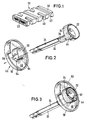
- Figure 1 shows a two-wire flat conductor cable 22.
- the sheathing 32 at its end has annular portions 38, openings 40 separating the annular portions, and limb portions 42 connecting same.
- the sheathing has a thickened portion 44 between its two portions 34 and 36.
- Figure 2 further shows the housing cover 46 with the cover plate 48, the outer casing portion 50, the hub 52 with the opening 54 and the two sides 56 and 58 defining the opening.
- the housing cover 46 is a known self-contained component.
- the two conductor portions 24 together with the spiral 26 are pushed into the central opening thereof or the hub 52, in the direction of the arrows shown in Figure 2. That gives the configuration shown in Figure 3.
- the thickened portion 44 lies in the opening 54 between the two sides 56 and 58.
- the side 58 may have a groove and the thickened portion 54 may have a projection. That is indicated in Figures 2 and 3. Irrespective of the detailed construction however the thickened portion 44 is clamped in position in the opening 54. In that arrangement the portion 34 of the injected sheathing lies with a further portion 80 against the outside surface of the hub 52.
- the housing bottom 60 has a bottom plate 62 and an inner casing portion 64.
- An opening 66 is provided in the latter.
- a tongue 68 and a groove 70 are provided in the sides of the inner casing portion 64, which define the opening.
- the portion 34 of the sheathing which embraces the end portion of the spiral 26 in turn has a thickened portion 72.
- a groove 74 and a tongue 76 are also arranged at the sides thereof.
- the thickened portion 72 together with the spiral 26 is moved towards the housing bottom 60 in the direction of the arrow indicated in Figure 4.
- the tongue 68 is pushed into the groove 74 and the tongue 76 is pushed into the groove 70, resulting in the configuration shown in Figure 5.
- the portion 34 bears against the inside surface of the inner casing portion 64 with a portion 82 adjoining the thickened portion 72.
- the spiral 26 is now firmly located or connected to the housing bottom 60.
- Figures 4 and 5 further clearly show that the portion 36 is bent over outwardly relative to the portion 34.
- the conductor portions 24 are also bent over outwardly in a corresponding fashion. Generally speaking, there is more space in the direction in which the conductor portions 24 then extend, than directly beside the housing bottom 60. Attention has already been directed to the advantage deriving therefrom.
- Figure 6 shows the housing 78 of the electrical cable assembly which is now finished, consisting of the housing bottom 60 and the housing cover 46.
Landscapes
- Engineering & Computer Science (AREA)
- Mechanical Engineering (AREA)
- Steering Controls (AREA)
Claims (2)
- Elektrischer Verbinder zum Verbinden von zwei gegeneinander verschiebbaren Leitern mit:einem Gehäuse (78) mit einer an einem (24) der beiden Leiter angeordneten Bodenplatte (60) und einem an dem anderen Leiter (24) angeordneten Deckel (46) undeinem durch das Gehäuse (78) zwischen dem Gehäuseboden (60) und dem Deckel (46) abgestützten langgestreckten Flachkabel (22), das mehrere langgestreckte, in Querrichtung auseinanderliegende Leiter in einer Kabelisolierung enthält, wobei das Kabel ein zu einer Spirale (26) gewikkeltes mittleres Gebiet und ein erstes und ein zweites entgegengesetzt gerichtetes Ende mit abgebogenen Abschnitten aufweist, die unter 90° von der Spirale (26) ausgehen, wobei das erste und das zweite Ende vom Deckel (46) und vom Gehäuseboden (60) ausgehen,dadurch gekennzeichnet, daßder Deckel (46) gegenüber dem Gehäuseboden (60) drehbar ist undein isolierender Schutzmantel (32) um das Kabel (22) geformt ist, der Mantel (32) die abgebogenen Abschnitte der Enden und die angrenzenden Abschnitte der Spirale (26) abdeckt und der Mantel (32) an mindestens einem der abgebogenen Abschnitte einen verdickten Abschnitt (72) aufweist,wobei der Gehäuseboden (60) eine durch ihn durchtretende Öffnung (66) aufweist, die den Durchtritt des mindestens einen abgebogenen Abschnittes zuläßt, die Öffnung (66) durch in einem Abstand voneinanderliegende Seitenkanten des Gehäusebodens (60) begrenzt wird und wobei die Seitenkanten des Gehäusebodens (60) und die verdickten Abschnitte (72) des einen abgebogenen Abschnittes zum Befestigen des verdickten Abschnittes (72) am Gehäuseboden (60) in einer Feder- und Nut-Beziehung (68, 74; 76, 70) in Anlage liegen.
- Elektrischer Verbinder nach Anspruch 1, dadurch gekennzeichnet, daß der verdickte Abschnitt (72) des mindestens einen umgebogenen Abschnittes ein Federelement (76) und ein Nutenelement (74) aufweist, die auseinanderliegen, und wobei die Seitenkanten des Gehäusebodens (60) zum Abstützen des verdickten Abschnittes (72) zwischen den Seitenkanten des Gehäusebodens (60) zueinander komplementäre, auseinanderliegende Federabschnitte (68) und Nutenabschnitte (70) aufweisen.
Applications Claiming Priority (4)
| Application Number | Priority Date | Filing Date | Title |
|---|---|---|---|
| DE4031235 | 1990-03-02 | ||
| DE4006704 | 1990-03-02 | ||
| DE4006704 | 1990-03-02 | ||
| DE4031235A DE4031235A1 (de) | 1990-03-02 | 1990-10-04 | Verbindungsvorrichtung |
Publications (3)
| Publication Number | Publication Date |
|---|---|
| EP0444584A2 EP0444584A2 (de) | 1991-09-04 |
| EP0444584A3 EP0444584A3 (en) | 1991-10-02 |
| EP0444584B1 true EP0444584B1 (de) | 1996-06-05 |
Family
ID=25890746
Family Applications (1)
| Application Number | Title | Priority Date | Filing Date |
|---|---|---|---|
| EP91102781A Expired - Lifetime EP0444584B1 (de) | 1990-03-02 | 1991-02-26 | Elektrische Kabelanordnung |
Country Status (4)
| Country | Link |
|---|---|
| US (1) | US5238419A (de) |
| EP (1) | EP0444584B1 (de) |
| AU (1) | AU632904B2 (de) |
| DE (2) | DE4031235A1 (de) |
Families Citing this family (34)
| Publication number | Priority date | Publication date | Assignee | Title |
|---|---|---|---|---|
| JP2971643B2 (ja) * | 1991-10-28 | 1999-11-08 | 矢崎総業株式会社 | ブラシレス電気信号伝達装置 |
| ATE149656T1 (de) * | 1991-11-26 | 1997-03-15 | Gore W L & Ass Gmbh | Schleppkettenersatz |
| DE4223308C1 (de) * | 1992-07-15 | 1994-02-03 | Gore W L & Ass Gmbh | Spiralkabeldose |
| CA2101040C (en) * | 1992-07-30 | 1998-08-04 | Minori Takagi | Video tape recorder with a monitor-equipped built-in camera |
| US5382172A (en) * | 1993-07-15 | 1995-01-17 | Klier; Jurgen | Spiral cable box |
| US5340330A (en) * | 1993-08-26 | 1994-08-23 | Black & Decker Inc. | Anti-kink control for electrical cords |
| WO1995023711A1 (de) * | 1994-03-05 | 1995-09-08 | Hans Joachim Bamert | Anordnung zum herstellen einer elektrischen verbindung zwischen zwei gegeneinander verdrehbaren teilen |
| KR0140588B1 (ko) * | 1994-03-09 | 1998-07-01 | 가다오까 마사다까 | 회전콘넥터 |
| FR2719709A1 (fr) * | 1994-05-04 | 1995-11-10 | Jaeger | Contacteur électrique tournant comprenant des moyens de liaison perfectionnés pour conducteur électrique souple. |
| FR2719708B1 (fr) * | 1994-05-04 | 1996-07-26 | Jaeger | Contacteur électrique tournant comprenant des moyens de liaison perfectionnés pour conducteur électrique souple. |
| DE4424180A1 (de) * | 1994-07-08 | 1996-01-11 | Thomas & Betts Gmbh | Justiereinrichtung für das Gehäuse eines Flachband-Stromleitungsverbinders von Gassack-Aufprall-Schutzeinrichtungen |
| DE4431719C2 (de) * | 1994-09-06 | 1997-12-18 | Thomas & Betts Gmbh | Justiereinrichtung für das Gehäuse eines Flachband-Stromleitungsverbinders von Gassack-Aufprall-Schutzeinrichtungen |
| FR2724777B1 (fr) * | 1994-09-21 | 1997-01-24 | Magneti Marelli France | Contacteur electrique tournant comprenant un surmoulage perfectionne pour conducteur electrique souple |
| DE4439383A1 (de) * | 1994-11-04 | 1996-05-09 | Odw Elektrik Gmbh | Elektrische Übertragungsdose |
| GB9425584D0 (en) * | 1994-12-19 | 1995-02-15 | Amp Great Britain | Air bag activating system and a strain relief sleeve therefor |
| US5645441A (en) * | 1995-05-18 | 1997-07-08 | Niles Parts Co., Ltd. | Rotary connector device |
| US5616045A (en) * | 1995-07-14 | 1997-04-01 | Augat Inc. | Squib connector for automotive air bag assembly |
| JPH09148026A (ja) * | 1995-11-24 | 1997-06-06 | Yazaki Corp | 相対回転部材間継電装置 |
| GB9524905D0 (en) * | 1995-12-05 | 1996-02-07 | Amp Great Britain | air bag activating system and a strain relief sleeve therefor |
| US5882224A (en) * | 1996-08-28 | 1999-03-16 | Thomas & Betts International, Inc. | Squib connector socker assembly having shorting clip for automotive air bags |
| USD404363S (en) | 1996-09-27 | 1999-01-19 | Hamilton Beach/Proctor-Silex, Inc. | Cord guard |
| DE29617237U1 (de) * | 1996-10-04 | 1996-11-14 | Alcatel, Paris | Vorrichtung zur Stromübertragung zwischen zwei relativ zueinander bewegbaren Endstellen |
| US5823817A (en) * | 1996-10-24 | 1998-10-20 | Hamilton Beach/Proctor-Silex, Inc. | Cord guard |
| DE19701510A1 (de) * | 1997-01-17 | 1998-07-23 | Stemmann Technik Gmbh | Signalleiter |
| USD406428S (en) * | 1997-07-02 | 1999-03-02 | Hamilton Beach/Proctor-Silex, Inc. | Cord guard |
| JP2000040574A (ja) * | 1998-07-23 | 2000-02-08 | Sumitomo Wiring Syst Ltd | ケーブルリールおよびケーブルリールの組立方法 |
| DE60043488D1 (de) * | 1999-10-13 | 2010-01-21 | Thomson Multimedia Sa | Kabeltrommel und mit einer solchen Kabeltrommel ausgestattete Vorrichtung zum Übertragen mittels elektromagnetischer Wellen |
| DE10103761A1 (de) * | 2001-01-27 | 2002-09-05 | Kostal Leopold Gmbh & Co Kg | Flexibles Flachbandkabel |
| DE10116295A1 (de) * | 2001-03-31 | 2002-10-10 | Nexans France S A | Vorrichtung zur Stromübertragung zwischen zwei Endstellen |
| DE20207400U1 (de) | 2002-05-06 | 2002-08-29 | TAKATA-PETRI (Ulm) GmbH, 89081 Ulm | Gehäuseteil für ein Airbagmodul |
| JP2004142704A (ja) * | 2002-10-28 | 2004-05-20 | Sumitomo Wiring Syst Ltd | スライドドアのケーブル配索支持部構造 |
| US8262408B1 (en) * | 2008-10-22 | 2012-09-11 | Distinct Intuitive Designs, LLC | Coaxial cable assembly connection structure and method |
| GB0905224D0 (en) * | 2009-03-26 | 2009-05-13 | Delphi Tech Inc | System for installation of an electrical cable |
| US9184534B1 (en) * | 2011-12-23 | 2015-11-10 | Andrew Errato, Jr. | Over-mold strain relief for an electrical power connector |
Family Cites Families (23)
| Publication number | Priority date | Publication date | Assignee | Title |
|---|---|---|---|---|
| US1668953A (en) * | 1926-04-10 | 1928-05-08 | Frederic W Erickson | Molding for electric cables |
| US3525536A (en) * | 1968-10-11 | 1970-08-25 | Eaton Yale & Towne | Vehicle safety apparatus positioned on steering wheel |
| GB1295138A (de) * | 1970-05-30 | 1972-11-01 | ||
| US3800068A (en) * | 1972-01-10 | 1974-03-26 | Belden Corp | Strain relief |
| US3818122A (en) * | 1973-05-29 | 1974-06-18 | Schjeldahl Co G T | Flexible printed circuit interconnecting cable |
| DE2454023C3 (de) * | 1974-11-14 | 1979-06-28 | Fa. Richard Bergner, 8540 Schwabach | Einrichtung zum elektrischen Verbinden zweier miteinander fluchtender Rohrleiter |
| US4290664A (en) * | 1979-09-28 | 1981-09-22 | Communications Systems, Inc. | Multiple outlet telephone line adapter |
| DE3560326D1 (en) * | 1985-03-01 | 1987-08-13 | Petri Ag | Connector for the electrical junction of protecting devices by gas bag |
| DE8505830U1 (de) * | 1985-03-01 | 1985-05-09 | Petri Ag, 8750 Aschaffenburg | Stromleitungsverbinder für die elektrische Zuleitung zu Gassack-Aufprall-Schutzeinrichtungen |
| DE3541287A1 (de) * | 1985-11-22 | 1987-05-27 | Kabelmetal Electro Gmbh | Vorrichtung zur stromuebertragung zwischen zwei relativ zueinander bewegbaren kontaktstellen |
| US4798544A (en) * | 1986-01-06 | 1989-01-17 | Minnesota Mining And Manufacturing Company | Low profile clip connector with integral contact support insert |
| US4744763A (en) * | 1986-04-15 | 1988-05-17 | Furukawa Electric Co., Ltd. | Connector device for a transmission line connecting two relatively rotating members |
| US4718860A (en) * | 1986-08-14 | 1988-01-12 | Minnesota Mining And Manufacturing Company | Tapered strain relief electrical interconnection system |
| US4838803A (en) * | 1986-10-21 | 1989-06-13 | Alps Electric Co., Ltd. | Connector device |
| DE3641706A1 (de) * | 1986-12-06 | 1988-06-16 | Kabelmetal Electro Gmbh | Vorrichtung zur stromuebertragung zwischen zwei relativ zueinander bewegbaren kontaktstellen |
| US4722690A (en) * | 1987-03-17 | 1988-02-02 | Methode Electronics, Inc. | Clock spring interconnector |
| US4824396A (en) * | 1987-05-27 | 1989-04-25 | Alps Electric Co., Ltd. | Electrical connection apparatus |
| US4844359A (en) * | 1987-12-10 | 1989-07-04 | Alps Electric Co., Ltd. | Cable reel |
| JPH0454713Y2 (de) * | 1988-04-04 | 1992-12-22 | ||
| SE465263B (sv) * | 1988-07-18 | 1991-08-19 | Gen Engineering Bv | Anordning foer elektrisk anslutning av utrustning, som aer anordnad i eller paa ett motorfordons ratt |
| DE3838114C1 (de) * | 1988-11-10 | 1989-12-21 | Kabelmetal Electro Gmbh, 3000 Hannover, De | |
| DE3935529A1 (de) * | 1989-10-25 | 1991-05-02 | Kabelmetal Electro Gmbh | Vorrichtung zur stromuebertragung zwischen zwei endstellen |
| DE8914384U1 (de) * | 1989-12-07 | 1990-02-01 | Kabelmetal Electro Gmbh, 30179 Hannover | Vorrichtung zur Stromübertragung zwischen zwei Endstellen |
-
1990
- 1990-10-04 DE DE4031235A patent/DE4031235A1/de not_active Withdrawn
-
1991
- 1991-02-26 EP EP91102781A patent/EP0444584B1/de not_active Expired - Lifetime
- 1991-02-26 DE DE69119929T patent/DE69119929T2/de not_active Expired - Fee Related
- 1991-02-28 US US07/662,531 patent/US5238419A/en not_active Expired - Lifetime
- 1991-03-01 AU AU72010/91A patent/AU632904B2/en not_active Ceased
Also Published As
| Publication number | Publication date |
|---|---|
| EP0444584A2 (de) | 1991-09-04 |
| EP0444584A3 (en) | 1991-10-02 |
| DE69119929D1 (de) | 1996-07-11 |
| AU7201091A (en) | 1991-03-01 |
| AU632904B2 (en) | 1993-01-14 |
| DE4031235A1 (de) | 1991-09-12 |
| DE69119929T2 (de) | 1997-01-16 |
| US5238419A (en) | 1993-08-24 |
Similar Documents
| Publication | Publication Date | Title |
|---|---|---|
| EP0444584B1 (de) | Elektrische Kabelanordnung | |
| US3763455A (en) | Electrically coupled steering column | |
| US4904205A (en) | Retractable booster cables | |
| EP0701927B1 (de) | Gerät zur elektrischen Verbindung zwischen einem drehenden Kontakt und einer stationären Stromquelle | |
| US20020134565A1 (en) | Electromagnetic shielding structure | |
| GB2235833A (en) | Insulation displacement barrel terminals. | |
| CA2246035A1 (en) | Sealed multiple-contact electrical connector | |
| US4157854A (en) | Steering column electrical connector arrangement | |
| US4780094A (en) | Extension cord of undercarpet flat cable | |
| US5059134A (en) | Apparatus for providing an electrical conduction path between two contact locations which are rotatable with respect to each other | |
| GB2085232A (en) | Power actuable antenna installations | |
| US4927365A (en) | Apparatus for providing an electrical conduction path between two contact locations which are rotatable with respect to each other | |
| EP0482937B1 (de) | Drehbarer Verbinder | |
| KR100295231B1 (ko) | 회전 코넥터장치 | |
| WO1997040556A1 (en) | Plug in raceway with socketless receptacle | |
| US5314341A (en) | Electrical connector device | |
| CA2037430C (en) | Airbag connecting device | |
| US7179111B2 (en) | Electrical connector | |
| US5679015A (en) | Device for the transmission of signals between two terminals | |
| US4886460A (en) | Electrical connector assembly for a steering wheel occupant cushion restraint system | |
| US5003129A (en) | Protecting structure for harness wired along telescopic steering column | |
| US5649832A (en) | Device for transmitting signals between two terminals | |
| US11757208B2 (en) | Wiring harness and protector | |
| US6783378B2 (en) | Device for transmitting current between two terminals | |
| US5032084A (en) | Apparatus for providing an electrical conduction path between two contact locations which are rotatable with respect to each other |
Legal Events
| Date | Code | Title | Description |
|---|---|---|---|
| PUAI | Public reference made under article 153(3) epc to a published international application that has entered the european phase |
Free format text: ORIGINAL CODE: 0009012 |
|
| PUAL | Search report despatched |
Free format text: ORIGINAL CODE: 0009013 |
|
| AK | Designated contracting states |
Kind code of ref document: A2 Designated state(s): BE CH DE ES FR GB IT LI LU NL SE |
|
| AK | Designated contracting states |
Kind code of ref document: A3 Designated state(s): BE CH DE ES FR GB IT LI LU NL SE |
|
| 17P | Request for examination filed |
Effective date: 19920219 |
|
| 17Q | First examination report despatched |
Effective date: 19931203 |
|
| RAP3 | Party data changed (applicant data changed or rights of an application transferred) |
Owner name: THOMAS & BETTS CORPORATION |
|
| GRAH | Despatch of communication of intention to grant a patent |
Free format text: ORIGINAL CODE: EPIDOS IGRA |
|
| GRAA | (expected) grant |
Free format text: ORIGINAL CODE: 0009210 |
|
| AK | Designated contracting states |
Kind code of ref document: B1 Designated state(s): BE CH DE ES FR GB IT LI LU NL SE |
|
| PG25 | Lapsed in a contracting state [announced via postgrant information from national office to epo] |
Ref country code: LI Effective date: 19960605 Ref country code: CH Effective date: 19960605 Ref country code: BE Effective date: 19960605 |
|
| REF | Corresponds to: |
Ref document number: 69119929 Country of ref document: DE Date of ref document: 19960711 |
|
| ITF | It: translation for a ep patent filed | ||
| PG25 | Lapsed in a contracting state [announced via postgrant information from national office to epo] |
Ref country code: ES Free format text: LAPSE BECAUSE OF FAILURE TO SUBMIT A TRANSLATION OF THE DESCRIPTION OR TO PAY THE FEE WITHIN THE PRESCRIBED TIME-LIMIT Effective date: 19960916 |
|
| ET | Fr: translation filed | ||
| REG | Reference to a national code |
Ref country code: CH Ref legal event code: PL |
|
| PGFP | Annual fee paid to national office [announced via postgrant information from national office to epo] |
Ref country code: ES Payment date: 19970217 Year of fee payment: 7 |
|
| PLBE | No opposition filed within time limit |
Free format text: ORIGINAL CODE: 0009261 |
|
| STAA | Information on the status of an ep patent application or granted ep patent |
Free format text: STATUS: NO OPPOSITION FILED WITHIN TIME LIMIT |
|
| 26N | No opposition filed | ||
| REG | Reference to a national code |
Ref country code: FR Ref legal event code: TP Ref country code: FR Ref legal event code: CA |
|
| REG | Reference to a national code |
Ref country code: GB Ref legal event code: IF02 |
|
| PGFP | Annual fee paid to national office [announced via postgrant information from national office to epo] |
Ref country code: LU Payment date: 20090304 Year of fee payment: 19 |
|
| PGFP | Annual fee paid to national office [announced via postgrant information from national office to epo] |
Ref country code: NL Payment date: 20090224 Year of fee payment: 19 |
|
| PGFP | Annual fee paid to national office [announced via postgrant information from national office to epo] |
Ref country code: GB Payment date: 20090227 Year of fee payment: 19 |
|
| PG25 | Lapsed in a contracting state [announced via postgrant information from national office to epo] |
Ref country code: IT Free format text: LAPSE BECAUSE OF NON-PAYMENT OF DUE FEES Effective date: 20080226 |
|
| PGFP | Annual fee paid to national office [announced via postgrant information from national office to epo] |
Ref country code: SE Payment date: 20090227 Year of fee payment: 19 Ref country code: IT Payment date: 20090226 Year of fee payment: 18 Ref country code: DE Payment date: 20090331 Year of fee payment: 19 |
|
| PGFP | Annual fee paid to national office [announced via postgrant information from national office to epo] |
Ref country code: FR Payment date: 20090217 Year of fee payment: 19 |
|
| REG | Reference to a national code |
Ref country code: NL Ref legal event code: V1 Effective date: 20100901 |
|
| EUG | Se: european patent has lapsed | ||
| GBPC | Gb: european patent ceased through non-payment of renewal fee |
Effective date: 20100226 |
|
| REG | Reference to a national code |
Ref country code: FR Ref legal event code: ST Effective date: 20101029 |
|
| PG25 | Lapsed in a contracting state [announced via postgrant information from national office to epo] |
Ref country code: FR Free format text: LAPSE BECAUSE OF NON-PAYMENT OF DUE FEES Effective date: 20100301 Ref country code: NL Free format text: LAPSE BECAUSE OF NON-PAYMENT OF DUE FEES Effective date: 20100901 |
|
| PG25 | Lapsed in a contracting state [announced via postgrant information from national office to epo] |
Ref country code: DE Free format text: LAPSE BECAUSE OF NON-PAYMENT OF DUE FEES Effective date: 20100901 |
|
| PG25 | Lapsed in a contracting state [announced via postgrant information from national office to epo] |
Ref country code: GB Free format text: LAPSE BECAUSE OF NON-PAYMENT OF DUE FEES Effective date: 20100226 |
|
| PG25 | Lapsed in a contracting state [announced via postgrant information from national office to epo] |
Ref country code: SE Free format text: LAPSE BECAUSE OF NON-PAYMENT OF DUE FEES Effective date: 20100227 Ref country code: LU Free format text: LAPSE BECAUSE OF NON-PAYMENT OF DUE FEES Effective date: 20100226 |