EP0749878B1 - Fahrzeug-Leitsystem - Google Patents
Fahrzeug-Leitsystem Download PDFInfo
- Publication number
- EP0749878B1 EP0749878B1 EP96810350A EP96810350A EP0749878B1 EP 0749878 B1 EP0749878 B1 EP 0749878B1 EP 96810350 A EP96810350 A EP 96810350A EP 96810350 A EP96810350 A EP 96810350A EP 0749878 B1 EP0749878 B1 EP 0749878B1
- Authority
- EP
- European Patent Office
- Prior art keywords
- bus
- control system
- computer
- force value
- computers
- Prior art date
- Legal status (The legal status is an assumption and is not a legal conclusion. Google has not performed a legal analysis and makes no representation as to the accuracy of the status listed.)
- Expired - Lifetime
Links
- 230000005540 biological transmission Effects 0.000 claims abstract 2
- 230000003137 locomotive effect Effects 0.000 claims description 9
- 238000001514 detection method Methods 0.000 description 2
- 238000010586 diagram Methods 0.000 description 2
- 238000000034 method Methods 0.000 description 2
- 230000002411 adverse Effects 0.000 description 1
- 230000001419 dependent effect Effects 0.000 description 1
- 238000011156 evaluation Methods 0.000 description 1
- 230000001960 triggered effect Effects 0.000 description 1
Images
Classifications
-
- B—PERFORMING OPERATIONS; TRANSPORTING
- B61—RAILWAYS
- B61C—LOCOMOTIVES; MOTOR RAILCARS
- B61C15/00—Maintaining or augmenting the starting or braking power by auxiliary devices and measures; Preventing wheel slippage; Controlling distribution of tractive effort between driving wheels
- B61C15/08—Preventing wheel slippage
-
- B—PERFORMING OPERATIONS; TRANSPORTING
- B60—VEHICLES IN GENERAL
- B60L—PROPULSION OF ELECTRICALLY-PROPELLED VEHICLES; SUPPLYING ELECTRIC POWER FOR AUXILIARY EQUIPMENT OF ELECTRICALLY-PROPELLED VEHICLES; ELECTRODYNAMIC BRAKE SYSTEMS FOR VEHICLES IN GENERAL; MAGNETIC SUSPENSION OR LEVITATION FOR VEHICLES; MONITORING OPERATING VARIABLES OF ELECTRICALLY-PROPELLED VEHICLES; ELECTRIC SAFETY DEVICES FOR ELECTRICALLY-PROPELLED VEHICLES
- B60L3/00—Electric devices on electrically-propelled vehicles for safety purposes; Monitoring operating variables, e.g. speed, deceleration or energy consumption
- B60L3/10—Indicating wheel slip ; Correction of wheel slip
-
- B—PERFORMING OPERATIONS; TRANSPORTING
- B60—VEHICLES IN GENERAL
- B60T—VEHICLE BRAKE CONTROL SYSTEMS OR PARTS THEREOF; BRAKE CONTROL SYSTEMS OR PARTS THEREOF, IN GENERAL; ARRANGEMENT OF BRAKING ELEMENTS ON VEHICLES IN GENERAL; PORTABLE DEVICES FOR PREVENTING UNWANTED MOVEMENT OF VEHICLES; VEHICLE MODIFICATIONS TO FACILITATE COOLING OF BRAKES
- B60T8/00—Arrangements for adjusting wheel-braking force to meet varying vehicular or ground-surface conditions, e.g. limiting or varying distribution of braking force
- B60T8/17—Using electrical or electronic regulation means to control braking
- B60T8/1701—Braking or traction control means specially adapted for particular types of vehicles
- B60T8/1705—Braking or traction control means specially adapted for particular types of vehicles for rail vehicles
-
- B—PERFORMING OPERATIONS; TRANSPORTING
- B60—VEHICLES IN GENERAL
- B60T—VEHICLE BRAKE CONTROL SYSTEMS OR PARTS THEREOF; BRAKE CONTROL SYSTEMS OR PARTS THEREOF, IN GENERAL; ARRANGEMENT OF BRAKING ELEMENTS ON VEHICLES IN GENERAL; PORTABLE DEVICES FOR PREVENTING UNWANTED MOVEMENT OF VEHICLES; VEHICLE MODIFICATIONS TO FACILITATE COOLING OF BRAKES
- B60T8/00—Arrangements for adjusting wheel-braking force to meet varying vehicular or ground-surface conditions, e.g. limiting or varying distribution of braking force
- B60T8/17—Using electrical or electronic regulation means to control braking
- B60T8/175—Brake regulation specially adapted to prevent excessive wheel spin during vehicle acceleration, e.g. for traction control
-
- B—PERFORMING OPERATIONS; TRANSPORTING
- B60—VEHICLES IN GENERAL
- B60L—PROPULSION OF ELECTRICALLY-PROPELLED VEHICLES; SUPPLYING ELECTRIC POWER FOR AUXILIARY EQUIPMENT OF ELECTRICALLY-PROPELLED VEHICLES; ELECTRODYNAMIC BRAKE SYSTEMS FOR VEHICLES IN GENERAL; MAGNETIC SUSPENSION OR LEVITATION FOR VEHICLES; MONITORING OPERATING VARIABLES OF ELECTRICALLY-PROPELLED VEHICLES; ELECTRIC SAFETY DEVICES FOR ELECTRICALLY-PROPELLED VEHICLES
- B60L2200/00—Type of vehicles
- B60L2200/26—Rail vehicles
-
- Y—GENERAL TAGGING OF NEW TECHNOLOGICAL DEVELOPMENTS; GENERAL TAGGING OF CROSS-SECTIONAL TECHNOLOGIES SPANNING OVER SEVERAL SECTIONS OF THE IPC; TECHNICAL SUBJECTS COVERED BY FORMER USPC CROSS-REFERENCE ART COLLECTIONS [XRACs] AND DIGESTS
- Y02—TECHNOLOGIES OR APPLICATIONS FOR MITIGATION OR ADAPTATION AGAINST CLIMATE CHANGE
- Y02T—CLIMATE CHANGE MITIGATION TECHNOLOGIES RELATED TO TRANSPORTATION
- Y02T30/00—Transportation of goods or passengers via railways, e.g. energy recovery or reducing air resistance
Definitions
- the invention relates to the field of control technology. It starts from one Control system for vehicles according to the preamble of the first claim. Such a control system can be used in particular for the control and regulation of rail-bound vehicles, especially for locomotives become.
- Multifunction Vehicle Bus A generic control system is described in the third part ("Multifunction Vehicle Bus ”) of the standardization proposal IEC 9 332 for a train data network, version 1.8, October 1994. It is a control system which Data between different computers via a so-called multifunction vehicle bus (Multifunction Vehicle Bus).
- the data exchange on the bus is coordinated by one or more bus managers.
- the data transfer takes place asynchronously, that means every computer or bus manager has its own clock. Because of this asynchrony it turns out that a computer at the time of arrival of new data is just not ready to receive and process them.
- the bus manager sends a series of data protocols during a so-called bus cycle.
- the transfer order of the data protocols is made by the bus manager fixed. It can happen that the order e.g.
- 16 ms can due to the asynchrony of the two devices when calculating the adhesion control data Dead times and fluctuations of up to 30 ms occur. Thereby the regulation may react too late to changed adhesion conditions. This has a negative impact on driving quality and performance the locomotive. On wet tracks you can even drive up a slope fail with a heavy load.
- the object of the present invention is to provide a control system in which such dead times and thus also the negative influences on the operation of a vehicle can be avoided.
- the essence of the invention is therefore that the data protocols which are used for the Operation of the vehicle are important to each other with a defined Time offset and that these specific data protocols in trigger an interrupt on the computer for which they are intended.
- the interrupt makes it possible for the data protocols to be processed immediately become.
- the time offset enables synchronization between the computers involved and ensures that the required data protocols occur in the correct order. This way, the distracting Dead times effectively avoided.
- the specific data protocols represent a setpoint, which from a first computer to a second computer is sent, and an actual value, which from the first computer to the second Computer is sent represents.
- the invention is particularly advantageous for Adhesion control of a locomotive used.
- a drive control unit a tensile or braking force setpoint, which in a drive control device is set. This results in an actual pulling or braking force value on. This is transmitted to the drive control unit, where it is used for the calculation a new setpoint. This will then become the Drive control device fed, and the process described above runs from new one.
- the adhesion properties an electric locomotive can be drastically improved.
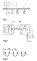
- Figure 1 shows a diagram of a control system according to the invention.
- 1 is one Designated bus, on which a number of computers 2 and at least one Bus manager 3 is connected.
- the computers 2 exchange among themselves the bus data and addresses.
- the data exchange is done by the or coordinated the bus managers 3.
- the data protocols are sent cyclically with a bus cycle time TB.
- the order or the time sequence of various data protocols is from Bus manager freely selectable, so that the order of the data protocols below Circumstances just reversed or the time interval between the data logs is too small or too large. More information about the definition of the data protocols etc. can use the standardization proposal mentioned at the beginning be removed. The content of this document is therefore intended to be related be taken into account with this description.
- Each computer 2 and each bus manager 3 works asynchronously, i.e. they own their own clock.
- Figure 2 shows an example of two computers 2, which are connected via bus 1.
- a drive control device 4 and a drive control device 5 e.g. an electric locomotive.
- the drive controller 10 is with a drive converter 6 connected and controls this.
- the converter 6 drives an engine 7.
- a speed detection 12 is provided, which measures an actual speed value of the wheels of the vehicle. For example by means of a known Wiegand sensor.
- the actual speed value and a traction or braking force actual value is now from the drive control device 5 via the Bus 1 transmitted to the drive control device 4.
- a new traction or braking force setpoint is calculated from this data. This is then transmitted to the drive control device 5 and set. A new actual value arises and the control loop is run through again.
- the drive control device 4 at the moment of arrival of the data from the drive control device 5 is not ready to record the data.
- This is an example less relevant data does not matter because the bus manager sends the data periodically with a bus cycle time TB.
- the drive control device 4 can so fetch the data at the next bus cycle. But this creates the Dead times mentioned at the beginning, which are for data which e.g. exclusively the Serve control and are therefore not time-critical, not a big influence play.
- the dead times can also be determined by any and only from the bus manager autonomously determined order of the data protocols within a Bus cycle arise. For example, the order of the target and actual values be reversed.
- Train and / or braking force setpoints and actual values are for the operation of the locomotive of fundamental importance, and the adhesion control that relies on it as well. Therefore these dead times should be avoided as far as possible. This is especially true because the adhesion control is very computationally intensive is.
- the dead times are avoided according to the invention in that the for Operation of the vehicle important data protocols - such as Actual speed value, Tension or braking force setpoints and actual values - with each other with a predefinable one Time offset tl be provided (see Fig. 3). This will change the order and the chronological sequence of the data protocols affected. Dead times through Swap the order or wait unnecessarily for the required ones This can avoid data.
- FIG Data logs Two different examples are shown, whose time offset within one Bus period TB is t1.
- the time offset t1 can be just one, for example half bus period, other values are of course also conceivable.
- the bus period TB was 16 ms, during 8 ms were selected for the time offset.
- the computers include a buffer 8 in which the data can be cached after arrival (see Fig. 2). At the same time an interrupt 9 is triggered, the data are in the corresponding Controller 10 or 11 loaded and then processed.
- the response time of the adhesion control was successful constantly set to less than 20 ms.
- the response time fluctuated between 63 ms and approx. 21 ms.
- this constant response time which is also reduced compared to the prior art could significantly improve the adhesion behavior of a electric locomotive can be reached.
Landscapes
- Engineering & Computer Science (AREA)
- Transportation (AREA)
- Mechanical Engineering (AREA)
- Sustainable Energy (AREA)
- Power Engineering (AREA)
- Life Sciences & Earth Sciences (AREA)
- Sustainable Development (AREA)
- Chemical & Material Sciences (AREA)
- Combustion & Propulsion (AREA)
- Electric Propulsion And Braking For Vehicles (AREA)
- Vehicle Body Suspensions (AREA)
- Bus Control (AREA)
- Small-Scale Networks (AREA)
Description
- Fig. 1
- Eine schematische Darstellung eines erfindungsgemässen Leitsystems;
- Fig. 2
- Einen Ausschnitt des erfindungsgemässen Leitsystems mit zwei miteinander kommunizierenden Rechnern;
- Fig. 3
- Ein Zeitdiagramm mit zwei verschiedenen Datenprotokollen.
- 1
- Bus
- 2
- Rechner
- 3
- Busverwalter
- 4
- Antriebsleitgerät
- 5
- Antriebskontrollgerät
- 6
- Antriebsstromrichter
- 7
- Motor
- 8
- Buffer
- 9
- Interrupt
- 10
- Antriebsregler
- 11
- Adhäsionsregler
- 12
- Drehzahlerfassung
Claims (6)
- Leitsystem für Fahrzeuge, insbesondere für schienengebundene Fahrzeuge, insbesondere Lokomotiven, umfassend einen Bus (1), an welchen mindestens zwei Rechner (2) und mindestens ein Busverwalter (3) angeschlossen ist, wobei jeder Rechner (2) und jeder Busverwalter (3) asynchron voneinander arbeiten und jeder Busverwalter (3) das Versenden von Datenprotokolle, welche auf dem Bus (1) zwischen den Rechnern (2) zirkulieren, koordiniert, dadurch gekennzeichnet, dass der Busverwalter (3) bestimmte Datenprotokolle, welche zum Betrieb des Fahrzeuges von Wichtigkeit sind und von mindestens zwei Rechnern (2) benötigt werden, mit einem von aussen vorgebbaren Zeitversatz (t1) versieht und dass diese bestimmten Datenprotokolle in den Rechnern (2), für welche sie bestimmt sind, einen Interrupt (9) auslösen.
- Leitsystem nach Anspruch 1, dadurch gekennzeichnet, dass die bestimmten Datenprotokolle einen Sollwert, welcher von einem ersten Rechner (2) zu einem zweiten Rechner (2) gesendet wird, und einen Istwert, welcher vom zweiten Rechner zum ersten gesendet wird, umfassen.
- Leitsystem nach Anspruch 2, dadurch gekennzeichnet, dass es sich bei dem Soll- bzw. Istwert um Zug- und/oder Bremskraftwerte handelt und der erste Rechner Bestandteil eines Antriebsleitgeräts (4) und der zweite Rechner Bestandteil eines Antriebskontrollgerätes (5) ist.
- Leitsystem nach Anspruch 3, dadurch gekennzeichnet, dass das Antriebsleitgerät (4) einen Zug- oder Bremskraftsollwert vorgibt, welcher im Antriebskontrollgerät (5) eingestellt wird und wodurch sich ein Zug- oder Bremskraftistwert einstellt, und dass dieser Zug- oder Bremskraftistwert vom Antriebskontrollgerät (4) an das Antriebsleitgerät (5) weitergeben wird, anhand dessen im Antriebsleitgerät (5) ein neuer Zug- oder Bremskraftsollwert berechnet wird.
- Leitsystem nach Anspruch 4, dadurch gekennzeichnet, dass der Zeitversatz (t1) kleiner oder gleich einer ersten Zeitperiode, welche zum Einstellen des Zug- oder Bremskraftsollwertes benötigt wird, und kleiner gleich einer zweiten Zeitperiode, welche zur Berechnung neuer Zug- oder Bremskraftsollwerte benötigt wird, gewählt wird.
- Leitsystem nach einem der Ansprüche 1 bis 5, dadurch gekennzeichnet, dass der oder jeder Busverwalter (3) die Datenprotokolle zyklisch mit einer Zeitperiode (TB) versendet und der Zeitversatz (t1) einer halben Zeitperiode (TB) entspricht.
Applications Claiming Priority (2)
| Application Number | Priority Date | Filing Date | Title |
|---|---|---|---|
| DE19522993A DE19522993A1 (de) | 1995-06-24 | 1995-06-24 | Fahrzeug Leitsystem |
| DE19522993 | 1995-06-24 |
Publications (2)
| Publication Number | Publication Date |
|---|---|
| EP0749878A1 EP0749878A1 (de) | 1996-12-27 |
| EP0749878B1 true EP0749878B1 (de) | 2000-09-06 |
Family
ID=7765171
Family Applications (1)
| Application Number | Title | Priority Date | Filing Date |
|---|---|---|---|
| EP96810350A Expired - Lifetime EP0749878B1 (de) | 1995-06-24 | 1996-05-31 | Fahrzeug-Leitsystem |
Country Status (5)
| Country | Link |
|---|---|
| EP (1) | EP0749878B1 (de) |
| AT (1) | ATE196124T1 (de) |
| DE (2) | DE19522993A1 (de) |
| DK (1) | DK0749878T3 (de) |
| ES (1) | ES2150087T3 (de) |
Families Citing this family (1)
| Publication number | Priority date | Publication date | Assignee | Title |
|---|---|---|---|---|
| DE102005040504B3 (de) | 2005-08-26 | 2007-04-05 | Knorr-Bremse Systeme für Schienenfahrzeuge GmbH | Verfahren und Vorrichtung zur Detektion von Störungen in Fahrwerken von durch Luftfedereinrichtungen gefederten Fahrzeugen |
Family Cites Families (9)
| Publication number | Priority date | Publication date | Assignee | Title |
|---|---|---|---|---|
| DE3837908A1 (de) * | 1988-11-04 | 1990-05-10 | Licentia Gmbh | Verfahren und anordnung zur regelung der antriebs- und/oder bremskraft der fahrmotoren eines laufachsenlosen triebfahrzeuges an der kraftschlussgrenze der raeder |
| JP2834808B2 (ja) * | 1989-12-08 | 1998-12-14 | 三菱電機株式会社 | 自動車用制御装置 |
| DE4022671A1 (de) * | 1990-07-17 | 1992-01-23 | Wabco Westinghouse Fahrzeug | Elektronisches bremssystem fuer stassenfahrzeuge |
| DE4214644A1 (de) * | 1992-05-02 | 1993-11-04 | Bosch Gmbh Robert | Steuerungssystem |
| DE4224581C1 (de) * | 1992-07-22 | 1993-12-02 | Aeg Westinghouse Transport | Verfahren zur Regelung der Antriebs- und/oder Bremskraft der Fahrmotoren eines Triebfahrzeuges an der Kraftschlußgrenze der Räder |
| DE4241790B4 (de) * | 1992-12-11 | 2016-06-09 | Robert Bosch Gmbh | Verfahren und Vorrichtung zum Betreiben von Steuereinrichtungen insbesondere für Fahrzeuge |
| DE4312949A1 (de) * | 1993-04-21 | 1994-10-27 | Abb Research Ltd | Verfahren zur Steuerung und Regelung eines elektrischen Antriebes eines Fahrzeuges |
| DE4327455A1 (de) * | 1993-08-16 | 1995-02-23 | Hella Kg Hueck & Co | System zur Ansteuerung eines Stellgliedes zur Einstellung der Luftzufuhr eines Kraftfahrzeugmotors |
| DE4339570B4 (de) * | 1993-11-19 | 2004-03-04 | Robert Bosch Gmbh | Elektronisches Bremssystem |
-
1995
- 1995-06-24 DE DE19522993A patent/DE19522993A1/de not_active Withdrawn
-
1996
- 1996-05-31 DE DE59605838T patent/DE59605838D1/de not_active Expired - Lifetime
- 1996-05-31 ES ES96810350T patent/ES2150087T3/es not_active Expired - Lifetime
- 1996-05-31 DK DK96810350T patent/DK0749878T3/da active
- 1996-05-31 EP EP96810350A patent/EP0749878B1/de not_active Expired - Lifetime
- 1996-05-31 AT AT96810350T patent/ATE196124T1/de active
Also Published As
| Publication number | Publication date |
|---|---|
| DE59605838D1 (de) | 2000-10-12 |
| DK0749878T3 (da) | 2000-11-13 |
| ES2150087T3 (es) | 2000-11-16 |
| EP0749878A1 (de) | 1996-12-27 |
| DE19522993A1 (de) | 1997-01-02 |
| ATE196124T1 (de) | 2000-09-15 |
Similar Documents
| Publication | Publication Date | Title |
|---|---|---|
| DE69024724T2 (de) | Vorrichtung zur offenen steuerung für einen servomotor | |
| DE2255371C3 (de) | Speicheranordnung für Behälter, die Magnetbänder zur Datenspeicherung enthalten | |
| DE3587288T2 (de) | Verfahren zur steuerung eines roboters mit mehrfachem gelenk. | |
| EP0655682B1 (de) | Recheneinheit mit mehreren ausführbaren Tasks | |
| DE602005005772T2 (de) | Adaptives Schwingungsmanagementsystem für eine Arbeitsmaschine und Anwendungsmethode | |
| DE3417542A1 (de) | Blockierschutzeinrichtung mit einer fluidpumpe und einer fuer diese bestimmten antriebsschaltung | |
| DE2210704A1 (de) | Verfahren und Vorrichtung zur Datenverarbeitung | |
| DE3134091A1 (de) | Mikroprozessorgestuetzte prozesssteuerung | |
| EP3510456B1 (de) | Verfahren zum montieren eines objekts | |
| DE69507407T2 (de) | Verfahren, Vorrichtung und Einrichtung zur Servosteuerung eines von einem Motor angetriebenen physikalischen Systems auf einer vorbestimmten Trajektorie | |
| DE19749068A1 (de) | Verfahren und Vorrichtung zur Überwachung eines Rechnersystems bestehend aus wenigstens zwei Prozessoren | |
| CH668834A5 (de) | Verfahren zum kanalisieren des datenstroms von einer mehrzahl datenquellen an einen datenschreiber und einrichtung zur ausfuehrung dieses verfahrens. | |
| DE4005042C2 (de) | Mehrrechnersystem zur Durchführung von Bewegungssteuerungen | |
| DE2912073C2 (de) | ||
| DE3820717C2 (de) | ||
| EP0749878B1 (de) | Fahrzeug-Leitsystem | |
| EP4302159B1 (de) | Computerimplementiertes verfahren, vorrichtung zur datenverarbeitung und computersystem zum ansteuern einer regelungseinrichtung eines fördersystems | |
| DE19510247C2 (de) | Verfahren zur Datenübertragung | |
| DE4406258A1 (de) | Informationsverarbeitungsvorrichtung | |
| DE69216814T2 (de) | Verfahren zum steuern eines roboters | |
| DE1605388A1 (de) | Verfahren und Vorrichtung zur zentralisierten Steuerung der Fahrt von Zuegen | |
| DE102019203290B3 (de) | Verfahren zum Montieren von Bauteilen | |
| DE2442013A1 (de) | Verfahren und vorrichtung zur steuerung der uebertragung von daten | |
| DE102017106559A1 (de) | Auslegung oder Durchführung einer Bewegungsaufgabe einer bewegten Masse in einer mechanischen Anlage entlang zumindest einer Bewegungsachse | |
| EP0791193A1 (de) | Satzübergreifende geschwindigkeitsführung für beliebigen override-bereich |
Legal Events
| Date | Code | Title | Description |
|---|---|---|---|
| PUAI | Public reference made under article 153(3) epc to a published international application that has entered the european phase |
Free format text: ORIGINAL CODE: 0009012 |
|
| AK | Designated contracting states |
Kind code of ref document: A1 Designated state(s): AT CH DE DK ES FR GB IT LI SE |
|
| 17P | Request for examination filed |
Effective date: 19970509 |
|
| GRAG | Despatch of communication of intention to grant |
Free format text: ORIGINAL CODE: EPIDOS AGRA |
|
| GRAG | Despatch of communication of intention to grant |
Free format text: ORIGINAL CODE: EPIDOS AGRA |
|
| GRAH | Despatch of communication of intention to grant a patent |
Free format text: ORIGINAL CODE: EPIDOS IGRA |
|
| 17Q | First examination report despatched |
Effective date: 20000131 |
|
| RAP1 | Party data changed (applicant data changed or rights of an application transferred) |
Owner name: DAIMLERCHRYSLER AG |
|
| GRAH | Despatch of communication of intention to grant a patent |
Free format text: ORIGINAL CODE: EPIDOS IGRA |
|
| GRAA | (expected) grant |
Free format text: ORIGINAL CODE: 0009210 |
|
| AK | Designated contracting states |
Kind code of ref document: B1 Designated state(s): AT CH DE DK ES FR GB IT LI SE |
|
| REF | Corresponds to: |
Ref document number: 196124 Country of ref document: AT Date of ref document: 20000915 Kind code of ref document: T |
|
| ITF | It: translation for a ep patent filed | ||
| REG | Reference to a national code |
Ref country code: CH Ref legal event code: EP |
|
| ET | Fr: translation filed | ||
| REF | Corresponds to: |
Ref document number: 59605838 Country of ref document: DE Date of ref document: 20001012 |
|
| REG | Reference to a national code |
Ref country code: DK Ref legal event code: T3 |
|
| REG | Reference to a national code |
Ref country code: ES Ref legal event code: FG2A Ref document number: 2150087 Country of ref document: ES Kind code of ref document: T3 |
|
| GBT | Gb: translation of ep patent filed (gb section 77(6)(a)/1977) |
Effective date: 20001109 |
|
| REG | Reference to a national code |
Ref country code: GB Ref legal event code: 732E |
|
| PLBE | No opposition filed within time limit |
Free format text: ORIGINAL CODE: 0009261 |
|
| STAA | Information on the status of an ep patent application or granted ep patent |
Free format text: STATUS: NO OPPOSITION FILED WITHIN TIME LIMIT |
|
| REG | Reference to a national code |
Ref country code: FR Ref legal event code: TP |
|
| 26N | No opposition filed | ||
| REG | Reference to a national code |
Ref country code: CH Ref legal event code: PUE Owner name: DAIMLERCHRYSLER AG TRANSFER- DAIMLERCHRYSLER RAIL Ref country code: CH Ref legal event code: NV Representative=s name: ROTTMANN, ZIMMERMANN + PARTNER AG |
|
| REG | Reference to a national code |
Ref country code: GB Ref legal event code: IF02 |
|
| REG | Reference to a national code |
Ref country code: CH Ref legal event code: PFA Owner name: DAIMLERCHRYSLER RAIL SYSTEMS GMBH Free format text: DAIMLERCHRYSLER RAIL SYSTEMS GMBH#SAATWINKLER DAMM 43#13627 BERLIN (DE) -TRANSFER TO- DAIMLERCHRYSLER RAIL SYSTEMS GMBH#SAATWINKLER DAMM 43#13627 BERLIN (DE) |
|
| REG | Reference to a national code |
Ref country code: FR Ref legal event code: PLFP Year of fee payment: 20 |
|
| PGFP | Annual fee paid to national office [announced via postgrant information from national office to epo] |
Ref country code: SE Payment date: 20150520 Year of fee payment: 20 Ref country code: ES Payment date: 20150527 Year of fee payment: 20 Ref country code: DK Payment date: 20150520 Year of fee payment: 20 Ref country code: DE Payment date: 20150521 Year of fee payment: 20 Ref country code: CH Payment date: 20150521 Year of fee payment: 20 Ref country code: GB Payment date: 20150521 Year of fee payment: 20 |
|
| PGFP | Annual fee paid to national office [announced via postgrant information from national office to epo] |
Ref country code: AT Payment date: 20150521 Year of fee payment: 20 Ref country code: IT Payment date: 20150514 Year of fee payment: 20 Ref country code: FR Payment date: 20150521 Year of fee payment: 20 |
|
| REG | Reference to a national code |
Ref country code: DE Ref legal event code: R071 Ref document number: 59605838 Country of ref document: DE |
|
| REG | Reference to a national code |
Ref country code: DK Ref legal event code: EUP Effective date: 20160531 |
|
| REG | Reference to a national code |
Ref country code: CH Ref legal event code: PL |
|
| REG | Reference to a national code |
Ref country code: GB Ref legal event code: PE20 Expiry date: 20160530 |
|
| REG | Reference to a national code |
Ref country code: AT Ref legal event code: MK07 Ref document number: 196124 Country of ref document: AT Kind code of ref document: T Effective date: 20160531 |
|
| PG25 | Lapsed in a contracting state [announced via postgrant information from national office to epo] |
Ref country code: GB Free format text: LAPSE BECAUSE OF EXPIRATION OF PROTECTION Effective date: 20160530 |
|
| REG | Reference to a national code |
Ref country code: SE Ref legal event code: EUG |
|
| REG | Reference to a national code |
Ref country code: ES Ref legal event code: FD2A Effective date: 20160926 |
|
| PG25 | Lapsed in a contracting state [announced via postgrant information from national office to epo] |
Ref country code: ES Free format text: LAPSE BECAUSE OF EXPIRATION OF PROTECTION Effective date: 20160601 |