EP0749878B1 - Vehicle control system - Google Patents
Vehicle control system Download PDFInfo
- Publication number
- EP0749878B1 EP0749878B1 EP96810350A EP96810350A EP0749878B1 EP 0749878 B1 EP0749878 B1 EP 0749878B1 EP 96810350 A EP96810350 A EP 96810350A EP 96810350 A EP96810350 A EP 96810350A EP 0749878 B1 EP0749878 B1 EP 0749878B1
- Authority
- EP
- European Patent Office
- Prior art keywords
- bus
- control system
- computer
- force value
- computers
- Prior art date
- Legal status (The legal status is an assumption and is not a legal conclusion. Google has not performed a legal analysis and makes no representation as to the accuracy of the status listed.)
- Expired - Lifetime
Links
Images
Classifications
-
- B—PERFORMING OPERATIONS; TRANSPORTING
- B61—RAILWAYS
- B61C—LOCOMOTIVES; MOTOR RAILCARS
- B61C15/00—Maintaining or augmenting the starting or braking power by auxiliary devices and measures; Preventing wheel slippage; Controlling distribution of tractive effort between driving wheels
- B61C15/08—Preventing wheel slippage
-
- B—PERFORMING OPERATIONS; TRANSPORTING
- B60—VEHICLES IN GENERAL
- B60L—PROPULSION OF ELECTRICALLY-PROPELLED VEHICLES; SUPPLYING ELECTRIC POWER FOR AUXILIARY EQUIPMENT OF ELECTRICALLY-PROPELLED VEHICLES; ELECTRODYNAMIC BRAKE SYSTEMS FOR VEHICLES IN GENERAL; MAGNETIC SUSPENSION OR LEVITATION FOR VEHICLES; MONITORING OPERATING VARIABLES OF ELECTRICALLY-PROPELLED VEHICLES; ELECTRIC SAFETY DEVICES FOR ELECTRICALLY-PROPELLED VEHICLES
- B60L3/00—Electric devices on electrically-propelled vehicles for safety purposes; Monitoring operating variables, e.g. speed, deceleration or energy consumption
- B60L3/10—Indicating wheel slip ; Correction of wheel slip
-
- B—PERFORMING OPERATIONS; TRANSPORTING
- B60—VEHICLES IN GENERAL
- B60T—VEHICLE BRAKE CONTROL SYSTEMS OR PARTS THEREOF; BRAKE CONTROL SYSTEMS OR PARTS THEREOF, IN GENERAL; ARRANGEMENT OF BRAKING ELEMENTS ON VEHICLES IN GENERAL; PORTABLE DEVICES FOR PREVENTING UNWANTED MOVEMENT OF VEHICLES; VEHICLE MODIFICATIONS TO FACILITATE COOLING OF BRAKES
- B60T8/00—Arrangements for adjusting wheel-braking force to meet varying vehicular or ground-surface conditions, e.g. limiting or varying distribution of braking force
- B60T8/17—Using electrical or electronic regulation means to control braking
- B60T8/1701—Braking or traction control means specially adapted for particular types of vehicles
- B60T8/1705—Braking or traction control means specially adapted for particular types of vehicles for rail vehicles
-
- B—PERFORMING OPERATIONS; TRANSPORTING
- B60—VEHICLES IN GENERAL
- B60T—VEHICLE BRAKE CONTROL SYSTEMS OR PARTS THEREOF; BRAKE CONTROL SYSTEMS OR PARTS THEREOF, IN GENERAL; ARRANGEMENT OF BRAKING ELEMENTS ON VEHICLES IN GENERAL; PORTABLE DEVICES FOR PREVENTING UNWANTED MOVEMENT OF VEHICLES; VEHICLE MODIFICATIONS TO FACILITATE COOLING OF BRAKES
- B60T8/00—Arrangements for adjusting wheel-braking force to meet varying vehicular or ground-surface conditions, e.g. limiting or varying distribution of braking force
- B60T8/17—Using electrical or electronic regulation means to control braking
- B60T8/175—Brake regulation specially adapted to prevent excessive wheel spin during vehicle acceleration, e.g. for traction control
-
- B—PERFORMING OPERATIONS; TRANSPORTING
- B60—VEHICLES IN GENERAL
- B60L—PROPULSION OF ELECTRICALLY-PROPELLED VEHICLES; SUPPLYING ELECTRIC POWER FOR AUXILIARY EQUIPMENT OF ELECTRICALLY-PROPELLED VEHICLES; ELECTRODYNAMIC BRAKE SYSTEMS FOR VEHICLES IN GENERAL; MAGNETIC SUSPENSION OR LEVITATION FOR VEHICLES; MONITORING OPERATING VARIABLES OF ELECTRICALLY-PROPELLED VEHICLES; ELECTRIC SAFETY DEVICES FOR ELECTRICALLY-PROPELLED VEHICLES
- B60L2200/00—Type of vehicles
- B60L2200/26—Rail vehicles
-
- Y—GENERAL TAGGING OF NEW TECHNOLOGICAL DEVELOPMENTS; GENERAL TAGGING OF CROSS-SECTIONAL TECHNOLOGIES SPANNING OVER SEVERAL SECTIONS OF THE IPC; TECHNICAL SUBJECTS COVERED BY FORMER USPC CROSS-REFERENCE ART COLLECTIONS [XRACs] AND DIGESTS
- Y02—TECHNOLOGIES OR APPLICATIONS FOR MITIGATION OR ADAPTATION AGAINST CLIMATE CHANGE
- Y02T—CLIMATE CHANGE MITIGATION TECHNOLOGIES RELATED TO TRANSPORTATION
- Y02T30/00—Transportation of goods or passengers via railways, e.g. energy recovery or reducing air resistance
Definitions
- the invention relates to the field of control technology. It starts from one Control system for vehicles according to the preamble of the first claim. Such a control system can be used in particular for the control and regulation of rail-bound vehicles, especially for locomotives become.
- Multifunction Vehicle Bus A generic control system is described in the third part ("Multifunction Vehicle Bus ”) of the standardization proposal IEC 9 332 for a train data network, version 1.8, October 1994. It is a control system which Data between different computers via a so-called multifunction vehicle bus (Multifunction Vehicle Bus).
- the data exchange on the bus is coordinated by one or more bus managers.
- the data transfer takes place asynchronously, that means every computer or bus manager has its own clock. Because of this asynchrony it turns out that a computer at the time of arrival of new data is just not ready to receive and process them.
- the bus manager sends a series of data protocols during a so-called bus cycle.
- the transfer order of the data protocols is made by the bus manager fixed. It can happen that the order e.g.
- 16 ms can due to the asynchrony of the two devices when calculating the adhesion control data Dead times and fluctuations of up to 30 ms occur. Thereby the regulation may react too late to changed adhesion conditions. This has a negative impact on driving quality and performance the locomotive. On wet tracks you can even drive up a slope fail with a heavy load.
- the object of the present invention is to provide a control system in which such dead times and thus also the negative influences on the operation of a vehicle can be avoided.
- the essence of the invention is therefore that the data protocols which are used for the Operation of the vehicle are important to each other with a defined Time offset and that these specific data protocols in trigger an interrupt on the computer for which they are intended.
- the interrupt makes it possible for the data protocols to be processed immediately become.
- the time offset enables synchronization between the computers involved and ensures that the required data protocols occur in the correct order. This way, the distracting Dead times effectively avoided.
- the specific data protocols represent a setpoint, which from a first computer to a second computer is sent, and an actual value, which from the first computer to the second Computer is sent represents.
- the invention is particularly advantageous for Adhesion control of a locomotive used.
- a drive control unit a tensile or braking force setpoint, which in a drive control device is set. This results in an actual pulling or braking force value on. This is transmitted to the drive control unit, where it is used for the calculation a new setpoint. This will then become the Drive control device fed, and the process described above runs from new one.
- the adhesion properties an electric locomotive can be drastically improved.
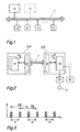
- Figure 1 shows a diagram of a control system according to the invention.
- 1 is one Designated bus, on which a number of computers 2 and at least one Bus manager 3 is connected.
- the computers 2 exchange among themselves the bus data and addresses.
- the data exchange is done by the or coordinated the bus managers 3.
- the data protocols are sent cyclically with a bus cycle time TB.
- the order or the time sequence of various data protocols is from Bus manager freely selectable, so that the order of the data protocols below Circumstances just reversed or the time interval between the data logs is too small or too large. More information about the definition of the data protocols etc. can use the standardization proposal mentioned at the beginning be removed. The content of this document is therefore intended to be related be taken into account with this description.
- Each computer 2 and each bus manager 3 works asynchronously, i.e. they own their own clock.
- Figure 2 shows an example of two computers 2, which are connected via bus 1.
- a drive control device 4 and a drive control device 5 e.g. an electric locomotive.
- the drive controller 10 is with a drive converter 6 connected and controls this.
- the converter 6 drives an engine 7.
- a speed detection 12 is provided, which measures an actual speed value of the wheels of the vehicle. For example by means of a known Wiegand sensor.
- the actual speed value and a traction or braking force actual value is now from the drive control device 5 via the Bus 1 transmitted to the drive control device 4.
- a new traction or braking force setpoint is calculated from this data. This is then transmitted to the drive control device 5 and set. A new actual value arises and the control loop is run through again.
- the drive control device 4 at the moment of arrival of the data from the drive control device 5 is not ready to record the data.
- This is an example less relevant data does not matter because the bus manager sends the data periodically with a bus cycle time TB.
- the drive control device 4 can so fetch the data at the next bus cycle. But this creates the Dead times mentioned at the beginning, which are for data which e.g. exclusively the Serve control and are therefore not time-critical, not a big influence play.
- the dead times can also be determined by any and only from the bus manager autonomously determined order of the data protocols within a Bus cycle arise. For example, the order of the target and actual values be reversed.
- Train and / or braking force setpoints and actual values are for the operation of the locomotive of fundamental importance, and the adhesion control that relies on it as well. Therefore these dead times should be avoided as far as possible. This is especially true because the adhesion control is very computationally intensive is.
- the dead times are avoided according to the invention in that the for Operation of the vehicle important data protocols - such as Actual speed value, Tension or braking force setpoints and actual values - with each other with a predefinable one Time offset tl be provided (see Fig. 3). This will change the order and the chronological sequence of the data protocols affected. Dead times through Swap the order or wait unnecessarily for the required ones This can avoid data.
- FIG Data logs Two different examples are shown, whose time offset within one Bus period TB is t1.
- the time offset t1 can be just one, for example half bus period, other values are of course also conceivable.
- the bus period TB was 16 ms, during 8 ms were selected for the time offset.
- the computers include a buffer 8 in which the data can be cached after arrival (see Fig. 2). At the same time an interrupt 9 is triggered, the data are in the corresponding Controller 10 or 11 loaded and then processed.
- the response time of the adhesion control was successful constantly set to less than 20 ms.
- the response time fluctuated between 63 ms and approx. 21 ms.
- this constant response time which is also reduced compared to the prior art could significantly improve the adhesion behavior of a electric locomotive can be reached.
Abstract
Description
Die Erfindung bezieht sich auf das Gebiet der Leittechnik. Sie geht aus von einem Leitsystem für Fahrzeuge gemäss dem Oberbegriff des ersten Anspruchs. Ein solches Leitsystem kann insbesondere für die Steuerung und Regelung von schienengebundenen Fahrzeugen, insbesondere für Lokomotiven, eingesetzt werden.The invention relates to the field of control technology. It starts from one Control system for vehicles according to the preamble of the first claim. Such a control system can be used in particular for the control and regulation of rail-bound vehicles, especially for locomotives become.
Ein gattungsgemässes Leitsystem wird im dritten Teil ("Multifunction Vehicle Bus") des Normierungsvorschlages IEC 9 332 für ein Zugdatennetz, Version 1.8, Oktober 1994 beschrieben. Es handelt sich dabei um ein Leitsystem, welches Daten zwischen verschiedenen Rechnern über einen sogenannten Multifunktions-Fahrzeugbus (Multifunction Vehicle Bus) austauscht. Der Datenaustausch auf dem Bus wird von einem oder mehreren Busverwaltern koordiniert. Die Datenübertragung erfolgt asynchron, dass heisst jeder Rechner oder Busverwalter verfügt über einen eigenen Taktgeber (Clock). Durch diese Asynchronität kann es sich ergeben, dass ein Rechner im Zeitpunkt des Eintreffens von neuen Daten gerade nicht bereit ist, diese zu empfangen und abzuarbeiten. Der Busverwalter versendet während eines sogenannten Buszyklus eine Reihe von Datenprotokollen. Die Übertragungsreihenfolge der Datenprotokolle wird vom Busverwalter festgelegt. Dadurch kann es geschehen, dass die Reihenfolge z.B. zweier Datenprotokolle vertauscht wird, und die betroffenen Rechner die Daten erst dem nächsten Buszyklus entnehmen können. Aufgrund dieser beiden durch die Asynchronität bedingten Umstände entstehen Totzeiten in der Bearbeitung. Im Normalfall stört dies nicht allzu sehr, da in den meisten Fällen lediglich Steuerungsaufgaben abgearbeitet werden müssen, bei welchen es keine Rolle spielt, ob die Daten unmittelbar bearheitet werden oder nicht. Bei Daten, welche für den Betrieb des Fahrzeuges von Wichtigkeit sind können die Totzeiten jedoch nachteilige Folgen haben. So sind z.B, auch das Stromrichterleitgerät (SLG) und der Anstriebsstromrichterkontroller (ASC) einer Lokomotive über diesen Bus miteinander verbunden, und die Daten für die Adhäsionsregelung werden vom ASC über den Bus an das SLG gesendet und dort bearbeitet. Bei einer Rechenzeit von einigen Millisekunden und einem Buszyklus von z.B. 16 ms können aufgrund der Asynchronität der beiden Geräte bei der Berechnung der Adhäsionsregeldaten Totzeiten und Schwankungen bis zu 30 ms auftreten. Dadurch reagiert die Regelung unter Umständen zu spät auf veränderte Adhäsionsbedingungen. Dies wirkt sich negativ auf die Fahrqualität und die Leistungsfähigkeit der Lokomotive aus. Auf nasser Schiene kann sogar eine Anfahrt an einer Steigung mit einer schweren Last scheitern. A generic control system is described in the third part ("Multifunction Vehicle Bus ") of the standardization proposal IEC 9 332 for a train data network, version 1.8, October 1994. It is a control system which Data between different computers via a so-called multifunction vehicle bus (Multifunction Vehicle Bus). The data exchange on the bus is coordinated by one or more bus managers. The data transfer takes place asynchronously, that means every computer or bus manager has its own clock. Because of this asynchrony it turns out that a computer at the time of arrival of new data is just not ready to receive and process them. The bus manager sends a series of data protocols during a so-called bus cycle. The transfer order of the data protocols is made by the bus manager fixed. It can happen that the order e.g. two data protocols is exchanged, and the affected computers only the data can take the next bus cycle. Because of these two by the Circumstances caused by asynchrony result in dead times in the processing. in the Normally this does not bother you too much, since in most cases only control tasks have to be worked through, where it doesn't matter, whether the data is immediately processed or not. For data which for the operation of the vehicle can be of importance, however, the dead times have adverse consequences. For example, the converter control unit (SLG) and the drive converter controller (ASC) of a locomotive via this bus interconnected, and the data for the adhesion control are from ASC sent to the SLG via the bus and processed there. With a computing time of a few milliseconds and a bus cycle of e.g. 16 ms can due to the asynchrony of the two devices when calculating the adhesion control data Dead times and fluctuations of up to 30 ms occur. Thereby the regulation may react too late to changed adhesion conditions. This has a negative impact on driving quality and performance the locomotive. On wet tracks you can even drive up a slope fail with a heavy load.
Aufgabe der vorliegenden Erfindung ist es, ein Leitsystem anzugeben, bei welchem solche Totzeiten und damit auch die negativen Einflüsse auf den Betrieb eines Fahrzeuges vermieden werden können.The object of the present invention is to provide a control system in which such dead times and thus also the negative influences on the operation of a vehicle can be avoided.
Diese Aufgabe wird bei einem Leitsystem der eingangs genannten Art durch die Merkmale des ersten Anspruchs gelöst.This task is performed in a control system of the type mentioned by Features of the first claim solved.
Kern der Erfindung ist es also, dass diejenige Datenprotokolle, welche für den Betrieb des Fahrzeuges von Bedeutung sind, untereinander mit einem definierten Zeitversatz versehen werden und dass diese bestimmten Datenprotokolle in den Rechner, für die sie bestimmt sind, einen Interrupt auslösen.The essence of the invention is therefore that the data protocols which are used for the Operation of the vehicle are important to each other with a defined Time offset and that these specific data protocols in trigger an interrupt on the computer for which they are intended.
Durch den Interrupt wird es möglich, dass die Datenprotokolle unmittelbar abgearbeitet werden. Der Zeitversatz ermöglicht eine Synchronisation zwischen den beteiligten Rechnern und gewährleistet, dass die benötigten Datenprotokolle in der richtigen Reihenfolge auftreten. Auf diese Weise werden die störenden Totzeiten wirksam vermieden.The interrupt makes it possible for the data protocols to be processed immediately become. The time offset enables synchronization between the computers involved and ensures that the required data protocols occur in the correct order. This way, the distracting Dead times effectively avoided.
In einem realisierten Ausführungsbeispiel stellen die bestimmten Datenprotokolle einen Sollwert, welcher von einem ersten Rechner zu einem zweiten Rechner gesendet wird, und einen Istwert, welcher vom ersten Rechner zum zweiten Rechner gesendet wird, dar. Mit besonderem Vorteil wird die Erfindung für die Adhäsionsregelung einer Lokomotive eingesetzt. In diesem Fall gibt z.B. ein Antriebsleitgerät einen Zug- oder Bremskraftsollwert vor, welcher in einem Antriebkontrollgerät eingestellt wird. Dadurch stellt sich ein Zug- oder Bremskraftistwert ein. Dieser wird an das Antriebsleitgerät übermittelt, wo er zur Berechnung eines neuen Sollwertes dient. Dieser wird anschliessend wiederum dem Antriebskontrollgerät zugeleitet, und der oben geschilderte Prozess läuft von neuem ab. Mit dem erfindungsgemässen System konnten die Adhäsionseigenschaften einer elektrischen Lokomotive drastisch verbessert werden.In a realized exemplary embodiment, the specific data protocols represent a setpoint, which from a first computer to a second computer is sent, and an actual value, which from the first computer to the second Computer is sent represents. The invention is particularly advantageous for Adhesion control of a locomotive used. In this case e.g. a drive control unit a tensile or braking force setpoint, which in a drive control device is set. This results in an actual pulling or braking force value on. This is transmitted to the drive control unit, where it is used for the calculation a new setpoint. This will then become the Drive control device fed, and the process described above runs from new one. With the system according to the invention, the adhesion properties an electric locomotive can be drastically improved.
Weitere Ausführungsbeispiele ergeben sich aus den entsprechenden abhängigen Ansprüchen.Further exemplary embodiments result from the corresponding dependent Claims.
Nachfolgend wird die Erfindung anhand von Ausführungsbeispielen im Zusammenhang mit den Zeichnungen näher erläutert.In the following, the invention is described in connection with exemplary embodiments explained in more detail with the drawings.
Es zeigen:
- Fig. 1
- Eine schematische Darstellung eines erfindungsgemässen Leitsystems;
- Fig. 2
- Einen Ausschnitt des erfindungsgemässen Leitsystems mit zwei miteinander kommunizierenden Rechnern;
- Fig. 3
- Ein Zeitdiagramm mit zwei verschiedenen Datenprotokollen.
- Fig. 1
- A schematic representation of a control system according to the invention;
- Fig. 2
- A section of the control system according to the invention with two computers communicating with one another;
- Fig. 3
- A timing diagram with two different data protocols.
Die in den Zeichnungen verwendeten Bezugszeichen und deren Bedeutung sind in der Bezeichnungsliste zusammengefasst aufgelistet. Grundsätzlich sind in den Figuren gleiche Teile mit gleichen Bezugszeichen versehen.The reference numerals used in the drawings and their meaning are summarized in the list of labels. Basically are in the same parts with the same reference numerals.
Figur 1 zeigt ein Schema eines erfindungsgemässen Leitsystems. Mit 1 ist ein
Bus bezeichnet, an welchen ein Anzahl von Rechnern 2 und mindestens ein
Busverwalter 3 angeschlossen ist. Die Rechner 2 tauschen untereinander über
den Bus Daten und Adressen aus. Der Datenaustausch wird dabei von dem oder
den Busverwaltern 3 koordiniert.Figure 1 shows a diagram of a control system according to the invention. With 1 is one
Designated bus, on which a number of
Die Datenprotokolle werden zyklisch mit einer Buszykluszeit TB versendet. Die Reihenfolge bzw. die zeitliche Abfolge verschiedener Datenprotokolle ist vom Busverwalter frei wählbar, so dass die Reihenfolge der Datenprotokolle unter Umständen gerade vertauscht oder der zeitliche Abstand zwischen den Datenprotokollen zu gering oder zu gross ist. Weitere Informationen über die Definition der Datenprotokolle etc. können dem eingangs genannten Normierungsvorschlag entnommen werden. Der Inhalt dieses Dokuments soll deshalb in Zusammenhang mit dieser Beschreibung mit berücksichtigt werden.The data protocols are sent cyclically with a bus cycle time TB. The The order or the time sequence of various data protocols is from Bus manager freely selectable, so that the order of the data protocols below Circumstances just reversed or the time interval between the data logs is too small or too large. More information about the definition of the data protocols etc. can use the standardization proposal mentioned at the beginning be removed. The content of this document is therefore intended to be related be taken into account with this description.
Jeder Rechner 2 und jeder Busverwalter 3 arbeitet asynchron, d.h. sie besitzen
ihren eigenen Taktgeber (Clock). Figur 2 zeigt beispielhaft zwei Rechner 2, welche
über den Bus 1 verbunden sind. Es handelt sich einerseits um ein Antriebsleitgerät
4 und ein Antriebskontrollgerät 5 z.B. einer elektrischen Lokomotive.
Im Antriebsleitgerät 4 ist ein Adhäsionsregler 11 und im Antriebskontrollgerät 5
ein Antriebsregler 10 vorgesehen. Der Antriebsregler 10 ist mit einem Antriebsstromrichter
6 verbunden und steuert diesen an. Der Stromrichter 6 treibt
einen Motor 7 an. Ausserdem ist eine Drehzahlerfassung 12 vorgesehen, welche
einen Drehzahlistwert der Räder des Fahrzeuges misst. Dies kann beispielsweise
mittels eines bekannten Wiegand-Sensors erfolgen. Der Drehzahlistwert und
ein Zug- oder Bremskraftistwert wird nun vom Antriebskontrollgerät 5 über den
Bus 1 an das Antriebsleitgerät 4 übermittelt. Im Adhäsionsregler 11 wird dort
aus diesen Daten eine neuer Zug- oder Bremskraftsollwert berechnet. Dieser
wird anschliessend an das Antriebskontrollgerät 5 übermittelt und eingestellt.
Ein neuer Istwert stellt sich ein, und die Regelschleife wird von neuem durchlaufen. Each
Bei einem System nach dem Stand der Technik kann nun der Fall auftreten, dass z.B. das Antriebsleitgerät 4 im Moment der Ankunft der Daten vom Antriebskontrollgerät 5 nicht bereit zur Aufnahme der Daten ist. Dies spielt bei weniger relevanten Daten keine grosse Rolle, denn der Busverwalter versendet die Daten periodisch mit einer Buszykluszeit TB. Das Antriebsleitgerät 4 kann die Daten also beim nächsten Buszyklus abholen. Dadurch entstehen aber die eingangs erwähnten Totzeiten, welche für Daten, welche z.B. ausschliesslich der Steuerung dienen und daher nicht zeitkritisch sind, keinen grossen Einfluss spielen. Die Totzeiten können ebenfalls durch die beliebige und nur vom Busverwalter autonom bestimmte Reihenfolge der Datenprotokolle innerhalb eines Buszyklus entstehen. So kann beispielsweise die Reihenfolge der Soll- und Istwerte vertauscht sein.In a system according to the prior art, the case can now occur that e.g. the drive control device 4 at the moment of arrival of the data from the drive control device 5 is not ready to record the data. This is an example less relevant data does not matter because the bus manager sends the data periodically with a bus cycle time TB. The drive control device 4 can so fetch the data at the next bus cycle. But this creates the Dead times mentioned at the beginning, which are for data which e.g. exclusively the Serve control and are therefore not time-critical, not a big influence play. The dead times can also be determined by any and only from the bus manager autonomously determined order of the data protocols within a Bus cycle arise. For example, the order of the target and actual values be reversed.
Zug- und/oder Bremskraft-Soll- und Istwerte sind aber für den Betrieb der Lokomotive von grundsätzlicher Bedeutung, und die darauf angewiesene Adhäsionsregelung ebenso. Deshalb sollten diese Totzeiten tunlichst vermieden werden. Dies gilt insbesondere auch deshalb, weil die Adhäsionsregelung sehr rechenintensiv ist.Train and / or braking force setpoints and actual values are for the operation of the locomotive of fundamental importance, and the adhesion control that relies on it as well. Therefore these dead times should be avoided as far as possible. This is especially true because the adhesion control is very computationally intensive is.
Die Totzeiten werden nach der Erfindung dadurch vermieden, dass die für den Betrieb des Fahrzeuges wichtigen Datenprotokolle - wie z.B. Drehzahlistwert, Zug- oder Bremskraft-Soll- und Istwerte - untereinander mit einem vorgebbaren Zeitversatz tl versehen werden (siehe Fig. 3). Dadurch wird die Reihenfolge und die zeitliche Abfolge der betroffenen Datenprotokolle festgelegt. Totzeiten durch Vertauschen der Reihenfolge bzw. durch unnötiges Warten auf die benötigten Daten können dadurch vermieden werden. In Figur 3 sind beispielhaft zwei verschiedene Datenprotokolle dargestellt, deren Zeitversatz innerhalb einer Busperiode TB t1 beträgt. Der Zeitversatz t1 kann beispielsweise gerade eine halbe Busperiode betragen, andere Werte sind selbstverständlich auch denkbar. Beim realisierten Ausführungsbeispiel betrug die Busperiode TB 16 ms, während für den Zeitversatz 8 ms gewählt wurden. The dead times are avoided according to the invention in that the for Operation of the vehicle important data protocols - such as Actual speed value, Tension or braking force setpoints and actual values - with each other with a predefinable one Time offset tl be provided (see Fig. 3). This will change the order and the chronological sequence of the data protocols affected. Dead times through Swap the order or wait unnecessarily for the required ones This can avoid data. Two different examples are shown in FIG Data logs are shown, whose time offset within one Bus period TB is t1. The time offset t1 can be just one, for example half bus period, other values are of course also conceivable. In the realized embodiment, the bus period TB was 16 ms, during 8 ms were selected for the time offset.
Eine unmittelbare Auswertung der Datenprotokolle wird ausserdem dadurch erreicht,
dass die Datenprotokolle in den betroffenen Rechnern einen Interrupt
auslösen. Dadurch wird ein verzugsfreies Abarbeiten der Datenprotokolle gewährleistet,
und Totzeiten bedingt durch beschäftigte Rechner können vermieden
werden. Zu diesem Zweck umfassen die Rechner einen Buffer 8, in welchen
die Daten nach Ankunft zwischengespeichert werden können (siehe Fig. 2).
Gleichzeitig wird ein Interrupt 9 ausgelöst, die Daten werden in den entsprechenden
Regler 10 oder 11 geladen und nachfolgend abgearbeitet.An immediate evaluation of the data logs is also achieved by
that the data logs in the affected computers have an interrupt
trigger. This ensures that the data logs are processed without delay,
and dead times caused by busy computers can be avoided
become. For this purpose, the computers include a
Mit dem erfindungsgemässen System gelang es, die Reaktionszeit der Adhäsionsregelung konstant auf weniger als 20 ms einzustellen. Beim Stand der Technik schwankte die Reaktionszeit zwischen 63 ms und ca. 21 ms. Als Folge dieser konstanten und gegenüber dem Stand der Technik auch verringerten Reaktionszeit konnte eine erhebliche Verbesserung des Adhäsionsverhaltens einer elektrischen Lokomotive erreicht werden. With the system according to the invention, the response time of the adhesion control was successful constantly set to less than 20 ms. At the state of the Technology, the response time fluctuated between 63 ms and approx. 21 ms. As a result this constant response time, which is also reduced compared to the prior art could significantly improve the adhesion behavior of a electric locomotive can be reached.
- 11
- Busbus
- 22nd
- Rechnercomputer
- 33rd
- BusverwalterBus manager
- 44th
- AntriebsleitgerätDrive control unit
- 55
- AntriebskontrollgerätDrive control device
- 66
- AntriebsstromrichterDrive converter
- 77
- Motorengine
- 88th
- BufferBuffer
- 99
- InterruptInterrupt
- 1010th
- AntriebsreglerDrive controller
- 1111
- AdhäsionsreglerAdhesion regulator
- 1212th
- DrehzahlerfassungSpeed detection
Claims (6)
- Control system for vehicles, in particular for rail-bound vehicles, in particular locomotives, comprising a bus (1) to which at least two computers (2) and at least one bus manager (3) is [sic] connected, each computer (2) and each bus manager (3) operating asynchronously from one another and each bus manager (3) coordinating the transmission of data protocols which circulate on the bus (1) between the computers (2), characterized in that the bus manager (3) provides specific data protocols, which are important for the operation of the vehicle and are required by at least two computers (2), with a chronological offset (t1) which can be prescribed from the outside, and in that these specific data protocols trigger an interrupt (9) in the computers (2) for which they are intended.
- Control system according to Claim 1, characterized in that the specific data protocols comprise a desired value, which is transmitted from a first computer (2) to a second computer (2), and an actual value, which is transmitted from the second computer to the first.
- Control system according to Claim 2, characterized in that the desired value and actual value are traction force values and/or braking force values and the first computer is a component of a drive control unit (4) and the second computer is a component of a drive supervision unit (5).
- Control system according to Claim 3, characterized in that the drive control unit (4) prescribes a desired traction force value or desired braking force value which is set in the drive supervision unit (5), and as a result of which an actual traction force value or actual braking force value is set, and in that this actual traction force value or actual braking force value is passed on from the drive supervision unit (4) to the drive control unit (5) by means of which a new desired traction force value or desired braking force value is calculated in the drive control unit (5).
- Control system according to Claim 4, characterized in that the chronological offset (t1) is selected to be less than or equal to a first time period which is required to set the desired traction force value or desired braking force value and is selected to be less than or equal to a second time period which is required to calculate new desired traction force values or desired braking force values.
- Control system according to one of Claims 1 to 5, characterized in that the bus manager (3), or each bus manager (3), transmits the data protocols cyclically with a time period (TB), and the chronological offset (t1) corresponds to half a time period (TB).
Applications Claiming Priority (2)
| Application Number | Priority Date | Filing Date | Title |
|---|---|---|---|
| DE19522993 | 1995-06-24 | ||
| DE19522993A DE19522993A1 (en) | 1995-06-24 | 1995-06-24 | Vehicle guidance system |
Publications (2)
| Publication Number | Publication Date |
|---|---|
| EP0749878A1 EP0749878A1 (en) | 1996-12-27 |
| EP0749878B1 true EP0749878B1 (en) | 2000-09-06 |
Family
ID=7765171
Family Applications (1)
| Application Number | Title | Priority Date | Filing Date |
|---|---|---|---|
| EP96810350A Expired - Lifetime EP0749878B1 (en) | 1995-06-24 | 1996-05-31 | Vehicle control system |
Country Status (5)
| Country | Link |
|---|---|
| EP (1) | EP0749878B1 (en) |
| AT (1) | ATE196124T1 (en) |
| DE (2) | DE19522993A1 (en) |
| DK (1) | DK0749878T3 (en) |
| ES (1) | ES2150087T3 (en) |
Families Citing this family (1)
| Publication number | Priority date | Publication date | Assignee | Title |
|---|---|---|---|---|
| DE102005040504B3 (en) | 2005-08-26 | 2007-04-05 | Knorr-Bremse Systeme für Schienenfahrzeuge GmbH | Method and device for detecting disturbances in landing gear of vehicles sprung by pneumatic suspension devices |
Family Cites Families (9)
| Publication number | Priority date | Publication date | Assignee | Title |
|---|---|---|---|---|
| DE3837908A1 (en) * | 1988-11-04 | 1990-05-10 | Licentia Gmbh | Method and arrangement for controlling the drive force and/or braking force of the drive motors of a running axle-less tractor unit at the frictional engagement limit of the wheels |
| JP2834808B2 (en) * | 1989-12-08 | 1998-12-14 | 三菱電機株式会社 | Automotive control device |
| DE4022671A1 (en) * | 1990-07-17 | 1992-01-23 | Wabco Westinghouse Fahrzeug | ELECTRONIC BRAKE SYSTEM FOR ROAD VEHICLES |
| DE4214644A1 (en) * | 1992-05-02 | 1993-11-04 | Bosch Gmbh Robert | Control system for brake pressure control in commercial vehicle - addresses individual modules by sequentially activating signal lines between modules starting with line between central control and first module |
| DE4224581C1 (en) * | 1992-07-22 | 1993-12-02 | Aeg Westinghouse Transport | Method for regulating the driving and / or braking force of the traction motors of a traction vehicle at the adhesion limit of the wheels |
| DE4241790B4 (en) * | 1992-12-11 | 2016-06-09 | Robert Bosch Gmbh | Method and device for operating control devices, in particular for vehicles |
| DE4312949A1 (en) * | 1993-04-21 | 1994-10-27 | Abb Research Ltd | Method for controlling and regulating an electric drive of a vehicle |
| DE4327455A1 (en) * | 1993-08-16 | 1995-02-23 | Hella Kg Hueck & Co | System for controlling an actuator for adjusting the air supply to a motor vehicle engine |
| DE4339570B4 (en) * | 1993-11-19 | 2004-03-04 | Robert Bosch Gmbh | Electronic braking system |
-
1995
- 1995-06-24 DE DE19522993A patent/DE19522993A1/en not_active Withdrawn
-
1996
- 1996-05-31 DE DE59605838T patent/DE59605838D1/en not_active Expired - Lifetime
- 1996-05-31 ES ES96810350T patent/ES2150087T3/en not_active Expired - Lifetime
- 1996-05-31 DK DK96810350T patent/DK0749878T3/en active
- 1996-05-31 EP EP96810350A patent/EP0749878B1/en not_active Expired - Lifetime
- 1996-05-31 AT AT96810350T patent/ATE196124T1/en active
Also Published As
| Publication number | Publication date |
|---|---|
| DE19522993A1 (en) | 1997-01-02 |
| DE59605838D1 (en) | 2000-10-12 |
| ES2150087T3 (en) | 2000-11-16 |
| DK0749878T3 (en) | 2000-11-13 |
| EP0749878A1 (en) | 1996-12-27 |
| ATE196124T1 (en) | 2000-09-15 |
Similar Documents
| Publication | Publication Date | Title |
|---|---|---|
| DE2255371C3 (en) | Storage arrangement for containers containing magnetic tapes for data storage | |
| EP0655682B1 (en) | Multitasking arithmetic unit | |
| DE602005005772T2 (en) | Adaptive vibration management system for a work machine and application method | |
| DE2210704A1 (en) | Method and device for data processing | |
| DE3134091A1 (en) | MICROPROCESSOR-AIDED PROCESS CONTROL | |
| EP1198378A1 (en) | Method for optimizing energy in the manner in which a vehicle or train is driven using kinetic energy | |
| EP3510456B1 (en) | Method for assembling an object | |
| DE3727017C2 (en) | ||
| DE19749068A1 (en) | Monitoring process for vehicle multiprocessor system | |
| CH668834A5 (en) | METHOD FOR CHANNELING THE DATA FLOW FROM A MULTIPLE DATA SOURCES TO A RECORDER AND DEVICE FOR CARRYING OUT THIS METHOD. | |
| DE4005042C2 (en) | Multi-computer system for performing motion controls | |
| DE2912073C2 (en) | ||
| EP0749878B1 (en) | Vehicle control system | |
| DE4406258A1 (en) | Information processing device | |
| DE102019203290B3 (en) | Method of assembling components | |
| DE1605388A1 (en) | Method and device for centralized control of the travel of trains | |
| DE2442013A1 (en) | METHOD AND DEVICE FOR CONTROLLING THE TRANSFER OF DATA | |
| DE102015012111A1 (en) | Method for operating a plurality of robots of a production plant | |
| EP0791193A1 (en) | Speed control for any override range effective over a plurality of blocks | |
| EP1051670B1 (en) | Method for controlling several stepping motor modules with prior loading of ramp data | |
| EP1137997B1 (en) | Multi-master bus system and method for operating the same | |
| DE10148331A1 (en) | Control of data bus access, particularly for use with a motor vehicle CAN bus, so that a reliable upper limit for interrupt loading of a microprocessor with given peripherals is guaranteed | |
| EP1515881A1 (en) | Method and device for setting a desired longitudinal deceleration or longitudinal acceleration | |
| DE2434454B2 (en) | Method for the numerical control of a cutting machine tool | |
| DE10229520A1 (en) | Controlling vehicle processes, involves copying output parameter of at least one faster task program at start of this program if such an output parameter provided for both faster and slower programs |
Legal Events
| Date | Code | Title | Description |
|---|---|---|---|
| PUAI | Public reference made under article 153(3) epc to a published international application that has entered the european phase |
Free format text: ORIGINAL CODE: 0009012 |
|
| AK | Designated contracting states |
Kind code of ref document: A1 Designated state(s): AT CH DE DK ES FR GB IT LI SE |
|
| 17P | Request for examination filed |
Effective date: 19970509 |
|
| GRAG | Despatch of communication of intention to grant |
Free format text: ORIGINAL CODE: EPIDOS AGRA |
|
| GRAG | Despatch of communication of intention to grant |
Free format text: ORIGINAL CODE: EPIDOS AGRA |
|
| GRAH | Despatch of communication of intention to grant a patent |
Free format text: ORIGINAL CODE: EPIDOS IGRA |
|
| 17Q | First examination report despatched |
Effective date: 20000131 |
|
| RAP1 | Party data changed (applicant data changed or rights of an application transferred) |
Owner name: DAIMLERCHRYSLER AG |
|
| GRAH | Despatch of communication of intention to grant a patent |
Free format text: ORIGINAL CODE: EPIDOS IGRA |
|
| GRAA | (expected) grant |
Free format text: ORIGINAL CODE: 0009210 |
|
| AK | Designated contracting states |
Kind code of ref document: B1 Designated state(s): AT CH DE DK ES FR GB IT LI SE |
|
| REF | Corresponds to: |
Ref document number: 196124 Country of ref document: AT Date of ref document: 20000915 Kind code of ref document: T |
|
| ITF | It: translation for a ep patent filed |
Owner name: DE DOMINICIS & MAYER S.R.L. |
|
| REG | Reference to a national code |
Ref country code: CH Ref legal event code: EP |
|
| ET | Fr: translation filed | ||
| REF | Corresponds to: |
Ref document number: 59605838 Country of ref document: DE Date of ref document: 20001012 |
|
| REG | Reference to a national code |
Ref country code: DK Ref legal event code: T3 |
|
| REG | Reference to a national code |
Ref country code: ES Ref legal event code: FG2A Ref document number: 2150087 Country of ref document: ES Kind code of ref document: T3 |
|
| GBT | Gb: translation of ep patent filed (gb section 77(6)(a)/1977) |
Effective date: 20001109 |
|
| REG | Reference to a national code |
Ref country code: GB Ref legal event code: 732E |
|
| PLBE | No opposition filed within time limit |
Free format text: ORIGINAL CODE: 0009261 |
|
| STAA | Information on the status of an ep patent application or granted ep patent |
Free format text: STATUS: NO OPPOSITION FILED WITHIN TIME LIMIT |
|
| REG | Reference to a national code |
Ref country code: FR Ref legal event code: TP |
|
| 26N | No opposition filed | ||
| REG | Reference to a national code |
Ref country code: CH Ref legal event code: PUE Owner name: DAIMLERCHRYSLER AG TRANSFER- DAIMLERCHRYSLER RAIL Ref country code: CH Ref legal event code: NV Representative=s name: ROTTMANN, ZIMMERMANN + PARTNER AG |
|
| REG | Reference to a national code |
Ref country code: GB Ref legal event code: IF02 |
|
| REG | Reference to a national code |
Ref country code: CH Ref legal event code: PFA Owner name: DAIMLERCHRYSLER RAIL SYSTEMS GMBH Free format text: DAIMLERCHRYSLER RAIL SYSTEMS GMBH#SAATWINKLER DAMM 43#13627 BERLIN (DE) -TRANSFER TO- DAIMLERCHRYSLER RAIL SYSTEMS GMBH#SAATWINKLER DAMM 43#13627 BERLIN (DE) |
|
| REG | Reference to a national code |
Ref country code: FR Ref legal event code: PLFP Year of fee payment: 20 |
|
| PGFP | Annual fee paid to national office [announced via postgrant information from national office to epo] |
Ref country code: SE Payment date: 20150520 Year of fee payment: 20 Ref country code: ES Payment date: 20150527 Year of fee payment: 20 Ref country code: DK Payment date: 20150520 Year of fee payment: 20 Ref country code: DE Payment date: 20150521 Year of fee payment: 20 Ref country code: CH Payment date: 20150521 Year of fee payment: 20 Ref country code: GB Payment date: 20150521 Year of fee payment: 20 |
|
| PGFP | Annual fee paid to national office [announced via postgrant information from national office to epo] |
Ref country code: AT Payment date: 20150521 Year of fee payment: 20 Ref country code: IT Payment date: 20150514 Year of fee payment: 20 Ref country code: FR Payment date: 20150521 Year of fee payment: 20 |
|
| REG | Reference to a national code |
Ref country code: DE Ref legal event code: R071 Ref document number: 59605838 Country of ref document: DE |
|
| REG | Reference to a national code |
Ref country code: DK Ref legal event code: EUP Effective date: 20160531 |
|
| REG | Reference to a national code |
Ref country code: CH Ref legal event code: PL |
|
| REG | Reference to a national code |
Ref country code: GB Ref legal event code: PE20 Expiry date: 20160530 |
|
| REG | Reference to a national code |
Ref country code: AT Ref legal event code: MK07 Ref document number: 196124 Country of ref document: AT Kind code of ref document: T Effective date: 20160531 |
|
| PG25 | Lapsed in a contracting state [announced via postgrant information from national office to epo] |
Ref country code: GB Free format text: LAPSE BECAUSE OF EXPIRATION OF PROTECTION Effective date: 20160530 |
|
| REG | Reference to a national code |
Ref country code: SE Ref legal event code: EUG |
|
| REG | Reference to a national code |
Ref country code: ES Ref legal event code: FD2A Effective date: 20160926 |
|
| PG25 | Lapsed in a contracting state [announced via postgrant information from national office to epo] |
Ref country code: ES Free format text: LAPSE BECAUSE OF EXPIRATION OF PROTECTION Effective date: 20160601 |