EP0749683A2 - A cleaning apparatus - Google Patents
A cleaning apparatus Download PDFInfo
- Publication number
- EP0749683A2 EP0749683A2 EP96202480A EP96202480A EP0749683A2 EP 0749683 A2 EP0749683 A2 EP 0749683A2 EP 96202480 A EP96202480 A EP 96202480A EP 96202480 A EP96202480 A EP 96202480A EP 0749683 A2 EP0749683 A2 EP 0749683A2
- Authority
- EP
- European Patent Office
- Prior art keywords
- cleaning
- cleaning tools
- robot arm
- tools
- anyone
- Prior art date
- Legal status (The legal status is an assumption and is not a legal conclusion. Google has not performed a legal analysis and makes no representation as to the accuracy of the status listed.)
- Granted
Links
Images


Classifications
-
- A—HUMAN NECESSITIES
- A01—AGRICULTURE; FORESTRY; ANIMAL HUSBANDRY; HUNTING; TRAPPING; FISHING
- A01J—MANUFACTURE OF DAIRY PRODUCTS
- A01J5/00—Milking machines or devices
- A01J5/017—Automatic attaching or detaching of clusters
- A01J5/0175—Attaching of clusters
-
- A—HUMAN NECESSITIES
- A01—AGRICULTURE; FORESTRY; ANIMAL HUSBANDRY; HUNTING; TRAPPING; FISHING
- A01J—MANUFACTURE OF DAIRY PRODUCTS
- A01J7/00—Accessories for milking machines or devices
- A01J7/02—Accessories for milking machines or devices for cleaning or sanitising milking machines or devices
- A01J7/025—Teat cup cleaning, e.g. by rinse jetters or nozzles
-
- A—HUMAN NECESSITIES
- A01—AGRICULTURE; FORESTRY; ANIMAL HUSBANDRY; HUNTING; TRAPPING; FISHING
- A01J—MANUFACTURE OF DAIRY PRODUCTS
- A01J7/00—Accessories for milking machines or devices
- A01J7/04—Accessories for milking machines or devices for treatment of udders or teats, e.g. for cleaning
-
- A—HUMAN NECESSITIES
- A01—AGRICULTURE; FORESTRY; ANIMAL HUSBANDRY; HUNTING; TRAPPING; FISHING
- A01K—ANIMAL HUSBANDRY; CARE OF BIRDS, FISHES, INSECTS; FISHING; REARING OR BREEDING ANIMALS, NOT OTHERWISE PROVIDED FOR; NEW BREEDS OF ANIMALS
- A01K1/00—Housing animals; Equipment therefor
- A01K1/12—Milking stations
Definitions
- the present invention relates to an apparatus for cleaning the teats of a dairy animals udder, provided with a cleaning member capable of being driven and taken, at least partly, under the udder of the dairy animal, the cleaning member being provided with at least two cleaning tools which are mounted to rotate about a respective shaft.
- the present invention aims at providing an implement such as described in the opening paragraph, with which it is possible to clean the teats of the udder intensively.
- the implement as meant in the opening paragraph is characterized in that the cleaning tools are provided with profiles, a profile being ridged in shape and having such dimensions, that the two cleaning tools, disposed side by side, enclose a space into which a teat can be drawn.
- the cleaning tools are of tubular shape.
- the axis of rotation of the cleaning tools are parallel to one another.
- the cleaning tools are made from a flexible material.
- the cleaning tools are each others mirror image.
- the surface layer of a cleaning tool is exchangeable, e.g. by means of a sleeve applied to the cleaning tool.
- a sleeve applied to the cleaning tool.
- the profiles of the cleaning tools are of a circular shape.
- a circular shape is particularly advantageous as it corresponds with the shape of a teat.
- the cleaning member is suitable for being placed on or near the end of the robot arm.
- the cleaning member is capable of being motor-driven and is provided on or near the extremity of a support to be placed under the dairy animal.
- the support is provided with a connecting and disconnecting member, by means of which it can be coupled to, or uncoupled from the robot arm.
- the support can be placed on or near the teat cups, while it is preferably secured to the teat cups by suction.
- the support can be provided with projections, preferably teat-shaped projections, which by applying a vacuum to the teat cups are drawn into the teat cups, so enabling the support to be secured by suction in a fixed position in relation to the teat cup cluster.
- the cleaning member is provided with cleaning tools and there are provided cleaning means for decontaminating the cleaning tools. Before the teats of another animal are cleaned with the cleaning tools, it is thus possible to decontaminate the cleaning tools, so minimizing the risk of cross infections.
- the cleaning tool/tools and/or cleaning member are able to be taken to a cleaning plant by the robot arm which is used for attaching the teat cups or by a separate robot arm.
- the cleaning plant comprises a container in which a cleaning or rinsing liquid can be provided.
- a second container is arranged in the first container and, according to a further feature of the invention, is provided with perforations.
- the second container is rotatable with respect to the outer container.
- In the container there is/are provided one or a plurality of brushes, by means of which, according to a further aspect of the invention, the cleaning tools are brushed down.
- a sensor for monitoring the quality of the cleaning or rinsing liquid in the container there is a sensor for monitoring the quality of the cleaning or rinsing liquid.
- the sensor performs luminous intensity measurements.
- the cleaning tools are fully or partly constituted by or have a surface constituted by a moisture-absorbing material having a texture or being made from a woven product or from a sponge-like material or constituted by a fully or partly closed cell structure, such as rubber or plastic-like material, said cleaning tools operating with a rubbing motion.
- the cleaning tools have a portion with an empty space.
- the apparatus can be provided with the feature that a liquid, such as a cleaning or disinfecting liquid, can be fed into the empty space, thereby enabling the surface of the cleaning tools to be moistened with it.
- the cleaning tools may be of an elastic material, such as rubber or plastic, assuming its operative shape at a certain pneumatic or hydraulic pressure.
- the apparatus can have the feature that the cleaning tools or the cleaning member is/are capable of being coupled or uncoupled by means of a quick-action attachment, such as a bayonet joint.
- the cleaning member is provided with protective means.
- these protective means comprise a contact strip which extends fully or partly along the cleaning tools.
- the contact strip enables a signal to pass when it is in contact with the dairy animal, causing the robot arm to move in a direction away from the point of contact.
- the protective means comprise a sensor or contact member provided on the top side of the shaft directed upward.
- the contact member is a switch or distance sensor which causes, according to a further aspect of the invention, the rotary motion of the cleaning tool to stop and/or brings about a movement of the robot arm in a direction away from the point of contact.
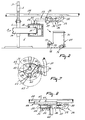
- FIG. 1 The apparatus depicted in Figure 1 has a robot arm 1 which, in the position marked by continuous lines, is in a condition of rest, and, in the position marked by dashed lines, is in operating condition.
- Figure 1 shows only the side portion of a cleaning/milking parlour. To the right and to the left, this cleaning/milking parlour is extended with common frame parts, gates for opening and closing to enable an animal, such as a cow, to enter and to leave the parlour, a feeder etc., the said parts having no direct connection with the invention.
- a milking/cleaning apparatus can be applied to the teats of the dairy animal's udder by swivelling robot arm 1.
- the robot arm 1 depicted in Figures 1 and 2 is suitable for taking both the cleaning apparatus and the teat cups under the animal to be milked. It stands to reason that separate robot arms can also be used for cleaning the teats and for attaching the teat cups.
- a robot arm 1 for attaching the teat cups has been described extensively in European Patent Application 0300582.
- the robot arm 1 is connected slidably in height with a frame beam 3 by means of a sliding sleeve 4 which is mounted slidably on the frame beam 3. Sliding the slidable sleeve 4 in upward direction is effected by means of a cylinder 5, one end of which is connected with the frame beam 3 and the other end with the sliding sleeve 4.
- the robot arm 1 can be swivelled about a substantially vertical hinge pin 6.
- the robot arm is swivelled about the vertical hinge pin 6 by means of a cylinder 7, one end of which is (rotatably) attached to a support 8 welded onto the frame beam 3 and the other end (rotatably) attached to a first portion 9 of the robot arm 1. It will be obvious that the robot arm 1 can be swivelled from the position of rest to the operating position, and vice versa, by operating the cylinder 7.
- a second portion 10 is pivotably mounted on a hinge pin 11 on the first portion 9 of the robot arm 1.
- the second portion 10 of the robot arm 1 can be swivelled about the hinge pin 11 by means of a cylinder 12 whose one end is secured to a support 13 of the first portion 9 of the robot arm 1 and whose other end is secured to a support 14 of the second portion 10 of the robot arm 1.
- the second portion 10 of the robot arm 1 can be swivelled about the hinge pin 11 into a desired angle A by means of the cylinder 12.
- the first portion 9 of the robot arm 1 comprises a portion 15 and a portion 16 which can turn in relation to one another as is indicated by the arrows in Figure 1.
- the two portions 15, 16 can be turned in relation to one another by means of a cylinder 17.
- One end of the cylinder 17 is connected with a support 18 mounted to the portion 15 and the other end is connected with a support 19 mounted on the portion 16.
- the second portion 10 of the robot arm 1 can be put at an angle to a horizontal plane by means of the cylinder 17.
- the first portion 9 of the robot arm 1 is also provided with a hinge 20 connecting a portion 21 with the portion 15.
- the hinge 20 is meant for protection of the robot arm 1. In the unlikely event of the animal treading on the second portion of the robot arm 1, the two portions 15 and 21 will pin-pivot in relation to one another against the action of springs, thus limiting the risk of the robot arm 1 being damaged to a considerable extent.
- a slide 22 Mounted on the second portion 10 of the robot arm 1 (see Figure 1) is a slide 22 which can be moved along a rail 23 through the activation of a (non-shown) control cylinder. On the slide 22 there are provided teat cups 24 as well as (non-shown) attachment means suitable for attaching the teat cups 24 to the teats.
- a sensor 25 capable of detecting the animal's teats is provided on the slide 22.
- the signal produced by the sensor 25 is processed by a computer to generate a signal serving the operation of the control cylinders of the robot arm 1. This enables the end of the robot arm to follow continuously the relevant teats when the animal changes (to some extent) its position.
- a second robot arm 26 is provided.
- the second robot arm 26 comprises a shaft 27, of which one end is suspended in a bearing on the frame 28 and which shaft is provided with a gear wheel 29 meshing with a second gear wheel 30 fitted on the shaft of an electric motor 31 attached next to the bearing of the second robot arm 26 to the frame 28.
- a removable support 32 is attached to the free end of the second robot arm 26 which cranked through angle B and has a cleaning member 33 disposed on it.
- the bottom side of the support 32 is provided with a teat-shaped projection 34, by means of which it is possible to place the support 32 on the first robot arm 1.
- the first robot arm 1 with the teat cups 24 have to be taken to a position under the teat-shaped projections 34 of the support 32.
- the teat-shaped projections 34 are drawn into, and secured to, the teat cups 24 by suction, enabling the support 32, one end of which is provided with spring-steel strips 35 in holders 36, to be detached from the second robot arm 26.
- An electric motor 37 attached to the support 32 is for driving the cleaning member 33.
- the control of the electric motor 37 proceeds through a flexible electrical cable 38.
- the animal's teats should be cleaned.
- an identification system to identify a given animal and the sensor 25 which is located on the first robot arm 1 and which is capable of detecting the positions of the teats, the first robot arm is put into an appropriate position under computer control. All this being known to the art and being no part of the present invention, further details will not be described hereinafter.
- FIG 3 shows a top view of the cleaning member 33.
- the cleaning member 33 comprises a housing 39 accommodating cleaning tools 40 with shafts 41 and having the electric motor 37 attached.
- the electric motor 37 is to drive a shaft 42 on which a gear wheel 43 is mounted, with the gear wheel 43 being located within the housing 39.
- the shafts 41 are supported in bearings 44 fitted on the housing.
- gear wheels 45 are mounted at the end of the cleaning tools 40.
- a timing belt 46 connects the gear wheels 45 of the cleaning tools 40 to the gear wheel 43 of the electric motor 37. From Figure 5 it can be seen that the timing belt 46 is routed round the outer two gear wheels 43, 45 and is underneath the middle gear wheel 45.
- the situation of the timing belt 44 on the gear wheels 43, 45 results in a direction of rotation of the cleaning tools 40 as is indicated by the arrows 47 in Figure 5.
- a teat coming from above into the space between the cleaning tools 40 is drawn downward in between the cleaning tools owing to this direction of rotation.
- the rotational speed of the cleaning tools 40 is adjustable, with its value being roughly between 70 and 120 RPM.
- Figure 4 shows that the shafts 41 of the cleaning tools 40 have the other ends supported in bearings 48 fitted in brackets 49 extending underneath the cleaning tools 40.
- the brackets 49 prevent the shafts 41 of the cleaning tools 40 from flexing too far.
- a contact strip 50 encircling the cleaning member 33 and, like all other controllable elements of the apparatus, being connected to the computer ensures that the cleaning member 33 will not be damaged when it comes into contact with the animal.
- the computer sends the robot arm 1 in a direction away from the point of contact.
- a flexible cleaning tool 49 having a closed cell structure and having a profile 51 on the outer side.
- the profile 51 is ridged in shape and it has such dimensions that the two cleaning tools 40 disposed parallel and side by side enclose a space 52 formed by their profiles 51, into which a teat can be drawn.
- the surface of the cleaning tools 40 is that of a textured, moisture absorbing layer 53.
- the layer 53 is constituted by a replaceable sleeve pushed onto cleaning tool 40, as is indicated by the hatching in Figure 3. When the sleeve is worn and/or not cleanable any more, it should be renewed.
- a further alternative is to replace the whole cleaning tools 40 when they are soiled or worn. This is achieved e.g. by securing the shaft 41 in the housing 39 by means of a quick-action attachment, such as a bayonet joint.
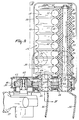
- FIG. 6 shows a different embodiment of the cleaning member; this cleaning member 54 is mounted on the support 32 in a similar way as is the cleaning member 33 mentioned before.
- the cleaning member 54 is atached by suction to the teat cups 24 by means of the teat-shaped projections 34 of the support 32.
- On the support 32 there is provided a housing 55, to whose bottom side an electric motor 56 is attached.
- the electric motor 56 is to drive a shaft 57 located in the housing 55 where it is supported in bearings.
- the shaft 57 is provided with a gear wheel 58, by means of which a timing belt 59 is driven.
- the cleaning member 54 has a shaft 60 supported in bearings in the housing 55 and its lower end is provided with a gear 61 carrying the timing belt 59 driven by the gear wheel 58 of the electric motor 56. At the other end of the shaft 60 there is provided a conical cap 62, to which strip-shaped pieces of cloth (cleaning tools) 63 are attached.
- the length of the pieces of cloth 63 measured with respect to the centre of the shaft 60 is about 240 mms.
- the rotary speed of the shaft 60 is about 450 RPM. At said rotary speed, the cleaning tools 63 assume an attitude which is upwardly sloping in radial direction under the influence of the centrifugal force exerted.
- a switch 62 which causes the rotation of the shaft 60 to stop when the switch 64 is operated by touching the animal.
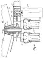
- the robot arm 1 puts the rotating pieces of cloth 63, which have been moistened to a certain extent, into such a position that they strike the teats and, owing to their flexibility, surround same.
- the two rotary paths 65 of the cleaning tools 63 are indicated by dashed lines.
- the cleaning members 54 are disposed such that the axes of rotation of the shafts 60 are inclined with respect to the support 32. Consequently, the two rotary paths 65 of the rotary cleaning tools 63 are parallel to each other. This makes it feasible to clean fore and hind teats at the same time.
- Figure 8 shows an other cleaning member 66. It is a sponge 67 which is provided on the support 32 and is capable of being set in motion by an electric motor 68. By pressing the sponge against the teats, the teats are rubbed clean. When rubbing, the sponge 67 moves in a plane parallel to the support 32. The path followed by the sponge 67 doing so can be in the shape of a circle or ellipse or any other pattern.
- the cleaning member 33, 54, 66 can be removed from the space under the animal by means of the robot arm 1. Then, the support 32 with the spring steel strips 35 is re-inserted into the holders 36. Subsequently, the vacuum of the teat cups 24 is released and the first robot arm 1 is disconnected from the support 32. Before cleaning another animal, it is possible to wash the cleaning member 33, 54, 66. Hereto, the electric motor 37, 56, 68 of the second robot arm 26 is energized, so that shaft 27 rotates through a certain angle.
- the washing machine 69 comprises a first container 70 and, disposed herein, a rotatable second container 71 provided with perforations.
- the first container 76 is capable of being filled with a cleaning or rinsing liquid by means of a pump 73 using a line 72 connected to the first container 76.
- the perforated container 72 ensures that the cleaning or rinsing liquid is agitated appropriately.
- the cleaning tools 40, 63, 67 are removed from the liquid and rotated at a high speed for some time. This causes the excess liquid to drop back into the first container 70.
- the electronic motor 31 can be energized again, causing the second robot arm 26 to return to its original position.
- a liquid-quality monitoring sensor 74 which tests the quality of the remaining cleaning or rinsing liquid. For instance, this is a luminous-intensity sensor.
- the dirtied liquid can be drained off by activation of the pump 73 and fresh cleaning or rinsing liquid be pumped into the container 70.
- the cleaning or rinsing liquid can be preheated. This can be realised by means of a heater coil or a (small-size) domestic heater.
Abstract
Description
- The present invention relates to an apparatus for cleaning the teats of a dairy animals udder, provided with a cleaning member capable of being driven and taken, at least partly, under the udder of the dairy animal, the cleaning member being provided with at least two cleaning tools which are mounted to rotate about a respective shaft.
- Such an implement is known.
- The present invention aims at providing an implement such as described in the opening paragraph, with which it is possible to clean the teats of the udder intensively.
- For this purpose the implement as meant in the opening paragraph, in accordance with the invention, is characterized in that the cleaning tools are provided with profiles, a profile being ridged in shape and having such dimensions, that the two cleaning tools, disposed side by side, enclose a space into which a teat can be drawn.
- Due to the fact that the teats are fully enclosed by the cleaning tools, the teats are cleaned on all sides.
- According to a feature of the invention, the cleaning tools are of tubular shape.
- According to a further feature of the invention, the axis of rotation of the cleaning tools are parallel to one another. According to another aspect of the invention, the cleaning tools are made from a flexible material.
- According to an aspect of the invention, the cleaning tools are each others mirror image.
- According to a feature of the invention, the surface layer of a cleaning tool is exchangeable, e.g. by means of a sleeve applied to the cleaning tool. When the sleeve is worn-out and/or not cleanable anymore, it can easily be renewed.
- According to a further aspect of the invention, the profiles of the cleaning tools are of a circular shape. A circular shape is particularly advantageous as it corresponds with the shape of a teat.
- According to a feature of the invention, the cleaning member is suitable for being placed on or near the end of the robot arm. In an advantageous embodiment of the invention, the cleaning member is capable of being motor-driven and is provided on or near the extremity of a support to be placed under the dairy animal.
- According to another aspect of the invention the support is provided with a connecting and disconnecting member, by means of which it can be coupled to, or uncoupled from the robot arm.
- According to a further feature of the invention, the support can be placed on or near the teat cups, while it is preferably secured to the teat cups by suction. According to a feature of the invention, hereto the support can be provided with projections, preferably teat-shaped projections, which by applying a vacuum to the teat cups are drawn into the teat cups, so enabling the support to be secured by suction in a fixed position in relation to the teat cup cluster.
- According to another aspect of the invention, the cleaning member is provided with cleaning tools and there are provided cleaning means for decontaminating the cleaning tools. Before the teats of another animal are cleaned with the cleaning tools, it is thus possible to decontaminate the cleaning tools, so minimizing the risk of cross infections.
- According to an aspect of the invention, the cleaning tool/tools and/or cleaning member are able to be taken to a cleaning plant by the robot arm which is used for attaching the teat cups or by a separate robot arm.
- According to a feature of the invention, the cleaning plant comprises a container in which a cleaning or rinsing liquid can be provided. A second container is arranged in the first container and, according to a further feature of the invention, is provided with perforations. According to a further feature, the second container is rotatable with respect to the outer container. In the container there is/are provided one or a plurality of brushes, by means of which, according to a further aspect of the invention, the cleaning tools are brushed down. In an advantageous embodiment of the invention, in the container there is a sensor for monitoring the quality of the cleaning or rinsing liquid. According to a further feature of the invention, the sensor performs luminous intensity measurements.
- According to a further aspect of the invention, the cleaning tools are fully or partly constituted by or have a surface constituted by a moisture-absorbing material having a texture or being made from a woven product or from a sponge-like material or constituted by a fully or partly closed cell structure, such as rubber or plastic-like material, said cleaning tools operating with a rubbing motion.
- The cleaning tools, according to another feature of the invention, have a portion with an empty space. According to the invention, the apparatus can be provided with the feature that a liquid, such as a cleaning or disinfecting liquid, can be fed into the empty space, thereby enabling the surface of the cleaning tools to be moistened with it.
- According to a feature of the invention, the cleaning tools may be of an elastic material, such as rubber or plastic, assuming its operative shape at a certain pneumatic or hydraulic pressure.
- According to the invention, the apparatus can have the feature that the cleaning tools or the cleaning member is/are capable of being coupled or uncoupled by means of a quick-action attachment, such as a bayonet joint.
- In a particular embodiment according to the invention, the cleaning member is provided with protective means. According to a further feature of the invention, these protective means comprise a contact strip which extends fully or partly along the cleaning tools. According to another aspect of the invention, the contact strip enables a signal to pass when it is in contact with the dairy animal, causing the robot arm to move in a direction away from the point of contact. According to another feature of the invention, the protective means comprise a sensor or contact member provided on the top side of the shaft directed upward. The contact member is a switch or distance sensor which causes, according to a further aspect of the invention, the rotary motion of the cleaning tool to stop and/or brings about a movement of the robot arm in a direction away from the point of contact.
- In explanation of the invention, a few embodiments of the apparatus according to the invention will now be described with reference to the accompanying drawings, in which:
- Figure 1 shows a top view of the apparatus for cleaning the teats of a dairy animal's udder;
- Figure 2 shows a side view of the apparatus depicted in Figure 1;
- Figure 3 is a top view of a first embodiment of the cleaning member as used in the apparatus depicted in Figure 1;
- Figure 4 shows a partial cut-away side view according to line IV-IV in Figure 3;
- Figure 5 shows a side view along the arrow V in Figure 3;
- Figure 6 shows a side view of a second embodiment of a cleaning member;
- Figure 7 is a top view of the paths described by the cleaning tools of the cleaning member accoding to Figure 6;
- Figure 8 is a side view of a third embodiment of a cleaning member.
- The apparatus depicted in Figure 1 has a robot arm 1 which, in the position marked by continuous lines, is in a condition of rest, and, in the position marked by dashed lines, is in operating condition. Figure 1 shows only the side portion of a cleaning/milking parlour. To the right and to the left, this cleaning/milking parlour is extended with common frame parts, gates for opening and closing to enable an animal, such as a cow, to enter and to leave the parlour, a feeder etc., the said parts having no direct connection with the invention.
- When an animal has taken its place on the milking/cleaning parlour 2, a milking/cleaning apparatus can be applied to the teats of the dairy animal's udder by swivelling robot arm 1. As will appear from the following, the robot arm 1 depicted in Figures 1 and 2 is suitable for taking both the cleaning apparatus and the teat cups under the animal to be milked. It stands to reason that separate robot arms can also be used for cleaning the teats and for attaching the teat cups.
- A robot arm 1 for attaching the teat cups has been described extensively in European Patent Application 0300582. The robot arm 1 is connected slidably in height with a frame beam 3 by means of a sliding sleeve 4 which is mounted slidably on the frame beam 3. Sliding the slidable sleeve 4 in upward direction is effected by means of a
cylinder 5, one end of which is connected with the frame beam 3 and the other end with the sliding sleeve 4. Furthermore, the robot arm 1 can be swivelled about a substantially vertical hinge pin 6. The robot arm is swivelled about the vertical hinge pin 6 by means of acylinder 7, one end of which is (rotatably) attached to asupport 8 welded onto the frame beam 3 and the other end (rotatably) attached to a first portion 9 of the robot arm 1. It will be obvious that the robot arm 1 can be swivelled from the position of rest to the operating position, and vice versa, by operating thecylinder 7. - A
second portion 10 is pivotably mounted on a hinge pin 11 on the first portion 9 of the robot arm 1. Thesecond portion 10 of the robot arm 1 can be swivelled about the hinge pin 11 by means of a cylinder 12 whose one end is secured to asupport 13 of the first portion 9 of the robot arm 1 and whose other end is secured to asupport 14 of thesecond portion 10 of the robot arm 1. Thesecond portion 10 of the robot arm 1 can be swivelled about the hinge pin 11 into a desired angle A by means of the cylinder 12. - The first portion 9 of the robot arm 1 comprises a
portion 15 and aportion 16 which can turn in relation to one another as is indicated by the arrows in Figure 1. The twoportions support 18 mounted to theportion 15 and the other end is connected with asupport 19 mounted on theportion 16. Thesecond portion 10 of the robot arm 1 can be put at an angle to a horizontal plane by means of the cylinder 17. - The first portion 9 of the robot arm 1 is also provided with a
hinge 20 connecting aportion 21 with theportion 15. Thehinge 20 is meant for protection of the robot arm 1. In the unlikely event of the animal treading on the second portion of the robot arm 1, the twoportions - Mounted on the
second portion 10 of the robot arm 1 (see Figure 1) is aslide 22 which can be moved along arail 23 through the activation of a (non-shown) control cylinder. On theslide 22 there are provided teat cups 24 as well as (non-shown) attachment means suitable for attaching the teat cups 24 to the teats. - Furthermore, a
sensor 25 capable of detecting the animal's teats is provided on theslide 22. The signal produced by thesensor 25 is processed by a computer to generate a signal serving the operation of the control cylinders of the robot arm 1. This enables the end of the robot arm to follow continuously the relevant teats when the animal changes (to some extent) its position. - Besides a first robot arm 1, a
second robot arm 26 is provided. Thesecond robot arm 26 comprises ashaft 27, of which one end is suspended in a bearing on theframe 28 and which shaft is provided with agear wheel 29 meshing with asecond gear wheel 30 fitted on the shaft of anelectric motor 31 attached next to the bearing of thesecond robot arm 26 to theframe 28. Aremovable support 32 is attached to the free end of thesecond robot arm 26 which cranked through angle B and has a cleaningmember 33 disposed on it. - The bottom side of the
support 32 is provided with a teat-shapedprojection 34, by means of which it is possible to place thesupport 32 on the first robot arm 1. To this end, the first robot arm 1 with the teat cups 24 have to be taken to a position under the teat-shapedprojections 34 of thesupport 32. By applying a vacuum to the teat cups 24, the teat-shapedprojections 34 are drawn into, and secured to, the teat cups 24 by suction, enabling thesupport 32, one end of which is provided with spring-steel strips 35 inholders 36, to be detached from thesecond robot arm 26. Anelectric motor 37 attached to thesupport 32 is for driving the cleaningmember 33. The control of theelectric motor 37 proceeds through a flexibleelectrical cable 38. - An alternative is to realise the control of the
electric motor 37 through contact strips which are located on the bottom side of thesupport 32, which contact strips make contact with contact strips located on the first robot arm 1 or thesecond robot arm 26, as the case may be, after thesupport 32 has been secured by suction. - Before the teat cups 24 are connected to the animal to be milked, the animal's teats should be cleaned. By means of an identification system to identify a given animal and the
sensor 25 which is located on the first robot arm 1 and which is capable of detecting the positions of the teats, the first robot arm is put into an appropriate position under computer control. All this being known to the art and being no part of the present invention, further details will not be described hereinafter. - Figure 3 shows a top view of the cleaning
member 33. The cleaningmember 33 comprises ahousing 39accommodating cleaning tools 40 withshafts 41 and having theelectric motor 37 attached. Theelectric motor 37 is to drive ashaft 42 on which agear wheel 43 is mounted, with thegear wheel 43 being located within thehousing 39. Theshafts 41 are supported inbearings 44 fitted on the housing. Situated within thehousing 39,gear wheels 45 are mounted at the end of thecleaning tools 40. Atiming belt 46 connects thegear wheels 45 of thecleaning tools 40 to thegear wheel 43 of theelectric motor 37. From Figure 5 it can be seen that thetiming belt 46 is routed round the outer twogear wheels middle gear wheel 45. The situation of thetiming belt 44 on thegear wheels cleaning tools 40 as is indicated by thearrows 47 in Figure 5. A teat coming from above into the space between thecleaning tools 40 is drawn downward in between the cleaning tools owing to this direction of rotation. Thus a "locating" action of thecleaning tools 40 is obtained. The rotational speed of thecleaning tools 40 is adjustable, with its value being roughly between 70 and 120 RPM. - Figure 4 shows that the
shafts 41 of thecleaning tools 40 have the other ends supported in bearings 48 fitted inbrackets 49 extending underneath thecleaning tools 40. Thebrackets 49 prevent theshafts 41 of thecleaning tools 40 from flexing too far. - A
contact strip 50 encircling the cleaningmember 33 and, like all other controllable elements of the apparatus, being connected to the computer ensures that the cleaningmember 33 will not be damaged when it comes into contact with the animal. To achieve this, the computer sends the robot arm 1 in a direction away from the point of contact. - Mounted on each of the
shafts 41 is aflexible cleaning tool 49 having a closed cell structure and having aprofile 51 on the outer side. Theprofile 51 is ridged in shape and it has such dimensions that the twocleaning tools 40 disposed parallel and side by side enclose aspace 52 formed by theirprofiles 51, into which a teat can be drawn. The surface of thecleaning tools 40 is that of a textured,moisture absorbing layer 53. Thelayer 53 is constituted by a replaceable sleeve pushed onto cleaningtool 40, as is indicated by the hatching in Figure 3. When the sleeve is worn and/or not cleanable any more, it should be renewed. - A further alternative is to replace the
whole cleaning tools 40 when they are soiled or worn. This is achieved e.g. by securing theshaft 41 in thehousing 39 by means of a quick-action attachment, such as a bayonet joint. - Figure 6 shows a different embodiment of the cleaning member; this cleaning member 54 is mounted on the
support 32 in a similar way as is the cleaningmember 33 mentioned before. The cleaning member 54 is atached by suction to the teat cups 24 by means of the teat-shapedprojections 34 of thesupport 32. On thesupport 32 there is provided ahousing 55, to whose bottom side an electric motor 56 is attached. The electric motor 56 is to drive ashaft 57 located in thehousing 55 where it is supported in bearings. Theshaft 57 is provided with a gear wheel 58, by means of which a timing belt 59 is driven. The cleaning member 54 has a shaft 60 supported in bearings in thehousing 55 and its lower end is provided with a gear 61 carrying the timing belt 59 driven by the gear wheel 58 of the electric motor 56. At the other end of the shaft 60 there is provided aconical cap 62, to which strip-shaped pieces of cloth (cleaning tools) 63 are attached. The length of the pieces ofcloth 63 measured with respect to the centre of the shaft 60 is about 240 mms. The rotary speed of the shaft 60 is about 450 RPM. At said rotary speed, thecleaning tools 63 assume an attitude which is upwardly sloping in radial direction under the influence of the centrifugal force exerted. In the vicinity of the top of theconical cap 62 there is provided aswitch 62 which causes the rotation of the shaft 60 to stop when theswitch 64 is operated by touching the animal. Thus, it is obviated that injuries are inflicted on the animal when the rotatingcone 62 is pressed against her. - The robot arm 1 puts the rotating pieces of
cloth 63, which have been moistened to a certain extent, into such a position that they strike the teats and, owing to their flexibility, surround same. Alternatively, it is also possible to dispose two such cleaning members 54 side by side. In Figure 7 the tworotary paths 65 of thecleaning tools 63 are indicated by dashed lines. The cleaning members 54 are disposed such that the axes of rotation of the shafts 60 are inclined with respect to thesupport 32. Consequently, the tworotary paths 65 of therotary cleaning tools 63 are parallel to each other. This makes it feasible to clean fore and hind teats at the same time. - Figure 8 shows an
other cleaning member 66. It is a sponge 67 which is provided on thesupport 32 and is capable of being set in motion by anelectric motor 68. By pressing the sponge against the teats, the teats are rubbed clean. When rubbing, the sponge 67 moves in a plane parallel to thesupport 32. The path followed by the sponge 67 doing so can be in the shape of a circle or ellipse or any other pattern. - After the cleaning of the teats, the cleaning
member support 32 with the spring steel strips 35 is re-inserted into theholders 36. Subsequently, the vacuum of the teat cups 24 is released and the first robot arm 1 is disconnected from thesupport 32. Before cleaning another animal, it is possible to wash the cleaningmember electric motor second robot arm 26 is energized, so thatshaft 27 rotates through a certain angle. The cleaningmember washing machine 69, In Figure 2, thewashing machine 69 comprises afirst container 70 and, disposed herein, a rotatablesecond container 71 provided with perforations. The first container 76 is capable of being filled with a cleaning or rinsing liquid by means of a pump 73 using aline 72 connected to the first container 76. Theperforated container 72 ensures that the cleaning or rinsing liquid is agitated appropriately. To prevent liquid from dripping from thecleaning tools cleaning tools first container 70. - After a given time, the
electronic motor 31 can be energized again, causing thesecond robot arm 26 to return to its original position. - In the
washing machine 69 there is provided a liquid-quality monitoring sensor 74 which tests the quality of the remaining cleaning or rinsing liquid. For instance, this is a luminous-intensity sensor. When it is detected that the liquid quality is insufficient, the dirtied liquid can be drained off by activation of the pump 73 and fresh cleaning or rinsing liquid be pumped into thecontainer 70. To achieve better cleaning results, the cleaning or rinsing liquid can be preheated. This can be realised by means of a heater coil or a (small-size) domestic heater.
Claims (12)
- An apparatus for cleaning the teats of a dairy animal's udder, provided with a cleaning member (33) capable of being driven and taken, at least partly, under the udder of the dairy animal, the cleaning member being proved with at least two cleaning tools (40) which are mounted to rotate about a respective shaft (41), characterized in that the cleaning tools (40) are provided with profiles (51), a profile being ridged in shape and having such dimensions, that the two cleaning tools (40), disposed side by side, enclose a space (52), into which a teat can be drawn.
- An apparatus as claimed in claim 1, characterized in that the cleaning tools (49) are of a tubular shape.
- An apparatus as claimed in claim 1 or 2, characterized in that the axis of rotation of the cleaning tools (40) are parallel to one another.
- An apparatus as claimed in claim 1, 2 or 3, characterized in that the cleaning tools (49) are made from a flexible material.
- An apparatus as claimed in anyone of claims 1 - 4, characterized in that the cleaning tools (40) are each other's mirror image.
- An apparatus as claimed in anyone of the preceding claims, characterized in that the cleaning tools (40) have a portion with an empty space, to which e.g. a cleaning or desinfecting liquid can be fed, enabling the surface of the cleaning tools (40) to be moistened with it.
- An apparatus as claimed in anyone of the preceding claims, characterized in that the cleaning tools (40) are of an elastic material, such as rubber or plastic, assuming its operative shape at a certain pneumatic or hydraulic pressure.
- An apparatus as claimed in anyone of the preceding claims, characterized in that the surface layer of a cleaning tool (40) is exchangeable e.g. through a sleeve applied to the cleaning tool (40).
- An apparatus as claimed in anyone of the preceding claims, characterized in that the cleaning tools (40) or the cleaning member (33) is/are capable of being coupled or uncoupled by means of a quick-action attachment, such as a bayonet joint.
- An apparatus as claimed in anyone of the preceding claims, characterized in that the cleaning member (33) is provided on or near the extremity of a support (32) to be placed under the dairy animal, by means of a robot arm (1).
- An apparatus as claimed in claim 10, characterized in that the support (32) is provided with a connecting and disconnecting member (35), by means of which it can be coupled to, or uncoupled from the robot arm (1).
- An apparatus as claimed in anyone of the preceding claims, characterized in that the profiles (51) of the cleaning tools (40) are of a circular shape.
Applications Claiming Priority (3)
| Application Number | Priority Date | Filing Date | Title |
|---|---|---|---|
| NL9002047A NL9002047A (en) | 1990-09-18 | 1990-09-18 | CLEANING INSTALLATION. |
| NL9002047 | 1990-09-18 | ||
| EP94203054A EP0643910B2 (en) | 1990-09-18 | 1991-09-17 | A cleaning apparatus |
Related Parent Applications (2)
| Application Number | Title | Priority Date | Filing Date |
|---|---|---|---|
| EP94203054A Division EP0643910B2 (en) | 1990-09-18 | 1991-09-17 | A cleaning apparatus |
| EP94203054.5 Division | 1991-09-17 |
Publications (3)
| Publication Number | Publication Date |
|---|---|
| EP0749683A2 true EP0749683A2 (en) | 1996-12-27 |
| EP0749683A3 EP0749683A3 (en) | 1998-03-18 |
| EP0749683B1 EP0749683B1 (en) | 1999-11-10 |
Family
ID=19857694
Family Applications (3)
| Application Number | Title | Priority Date | Filing Date |
|---|---|---|---|
| EP19910202364 Expired - Lifetime EP0476771B2 (en) | 1990-09-18 | 1991-09-17 | A cleaning apparatus |
| EP96202480A Expired - Lifetime EP0749683B1 (en) | 1990-09-18 | 1991-09-17 | A cleaning apparatus |
| EP94203054A Expired - Lifetime EP0643910B2 (en) | 1990-09-18 | 1991-09-17 | A cleaning apparatus |
Family Applications Before (1)
| Application Number | Title | Priority Date | Filing Date |
|---|---|---|---|
| EP19910202364 Expired - Lifetime EP0476771B2 (en) | 1990-09-18 | 1991-09-17 | A cleaning apparatus |
Family Applications After (1)
| Application Number | Title | Priority Date | Filing Date |
|---|---|---|---|
| EP94203054A Expired - Lifetime EP0643910B2 (en) | 1990-09-18 | 1991-09-17 | A cleaning apparatus |
Country Status (4)
| Country | Link |
|---|---|
| EP (3) | EP0476771B2 (en) |
| DE (3) | DE69109415T3 (en) |
| DK (1) | DK0476771T4 (en) |
| NL (1) | NL9002047A (en) |
Cited By (3)
| Publication number | Priority date | Publication date | Assignee | Title |
|---|---|---|---|---|
| WO1998042182A1 (en) * | 1997-03-26 | 1998-10-01 | Alfa Laval Agri Ab | A method and an apparatus for preparing a lactating animal for milking |
| WO2000076302A1 (en) * | 1999-06-11 | 2000-12-21 | Delaval Holding Ab | Method for cleaning teats of an animal |
| WO2009056592A1 (en) * | 2007-11-01 | 2009-05-07 | Delaval Holding Ab | An arrangement and a method for cleaning teats of animals |
Families Citing this family (21)
| Publication number | Priority date | Publication date | Assignee | Title |
|---|---|---|---|---|
| ATE214540T1 (en) * | 1991-10-04 | 2002-04-15 | Maasland Nv | DEVICE FOR MILKING ANIMALS |
| NL9200258A (en) * | 1991-10-04 | 1993-05-03 | Lely Nv C Van Der | METHOD FOR CLEANING MILK BEAKERS AND / OR AFTER-TREATMENT OF THE WEANING OF A MILKED ANIMAL, ANIMAL MILKING APPARATUS FOR USING THIS METHOD (S), AND A RINSE TOOL APPLIED IN SUCH AN APPARATUS. |
| NL9101673A (en) * | 1991-10-04 | 1993-05-03 | Texas Industries Inc | Apparatus for cleaning teats of milking animals. |
| NL9200091A (en) * | 1992-01-17 | 1993-08-16 | Lely Nv C Van Der | MILK MACHINE. |
| NL9200924A (en) * | 1992-05-26 | 1993-12-16 | Lely Nv C Van Der | DEVICE FOR AUTOMATIC MILKING OF ANIMALS. |
| NL9201734A (en) * | 1992-10-08 | 1994-05-02 | Lely Nv C Van Der | Device for automatic milking of animals. |
| GB2272626B (en) * | 1992-11-20 | 1996-11-06 | British Tech Group | Cleaning of milking animal teats |
| GB9224405D0 (en) * | 1992-11-20 | 1993-01-13 | Silsoe Research Inst | Cleaning of milking animal teats |
| NL9301098A (en) † | 1993-06-24 | 1995-01-16 | Texas Industries Inc | Device for automatic milking of animals. |
| NL9401802A (en) * | 1994-10-31 | 1996-06-03 | Maasland Nv | Device for milking animals. |
| NL9402010A (en) * | 1994-11-30 | 1996-07-01 | Maasland Nv | Device for milking animals. |
| NL9402158A (en) * | 1994-12-20 | 1996-08-01 | Maasland Nv | Device for automatically milking animals, such as cows. |
| NL9500364A (en) * | 1995-02-24 | 1996-10-01 | Maasland Nv | Device for milking animals. |
| NL1002173C2 (en) | 1996-01-25 | 1997-07-29 | Maasland Nv | Method of automatic milking of animals. |
| NL1006607C2 (en) * | 1997-07-17 | 1999-01-19 | Maasland Nv | Construction with a device for automatic milking of animals. |
| SE9704517D0 (en) | 1997-12-04 | 1997-12-04 | Alfa Laval Agri Ab | Teat cleaning brush |
| SE512397C2 (en) * | 1998-05-20 | 2000-03-13 | Alfa Laval Agri Ab | docking device |
| SE514037C2 (en) | 1998-08-31 | 2000-12-18 | Delaval Holding Ab | Method and apparatus for cleaning the teats of a dairy animal's udder |
| SE515114C2 (en) * | 1999-09-15 | 2001-06-11 | Delaval Holding Ab | Method and arrangement for washing a tension washing device |
| US10058069B2 (en) * | 2013-06-20 | 2018-08-28 | Delaval Holding Ab | Gripping device for a robotic manipulation device adapted to grip and attach teat cups to an animal |
| CN113261512B (en) * | 2021-05-28 | 2022-09-23 | 西藏净意科技有限公司 | Livestock breeding system based on big data monitoring |
Citations (8)
| Publication number | Priority date | Publication date | Assignee | Title |
|---|---|---|---|---|
| US2952860A (en) * | 1957-10-14 | 1960-09-20 | Palmer Fultz | Apparatus for cleaning cow's udder |
| GB976025A (en) * | 1962-06-25 | 1964-11-25 | Noel Lyttle | An improved device for use in washing the udders of cows |
| DD127384A1 (en) * | 1976-09-08 | 1977-09-21 | ||
| DD220212A1 (en) * | 1983-09-12 | 1985-03-27 | Univ Leipzig | DEVICE FOR CLEANING AND STIMULATING ANIMALS |
| FR2559351A1 (en) * | 1984-02-09 | 1985-08-16 | Marquaire Pierre | Device for washing and disinfecting teats before milking |
| WO1989000378A1 (en) * | 1987-07-22 | 1989-01-26 | Taittometalli Oy | Teat washing means |
| EP0309036A1 (en) * | 1987-09-24 | 1989-03-29 | Gascoigne-Melotte B.V. | Milking machine |
| EP0323444A2 (en) * | 1985-01-28 | 1989-07-05 | C. van der Lely N.V. | A device for milking animals, such as cows |
Family Cites Families (4)
| Publication number | Priority date | Publication date | Assignee | Title |
|---|---|---|---|---|
| SU374883A1 (en) * | 1971-11-09 | 1984-10-23 | Государственное Специальное Конструкторское Бюро По Комплексу Машин Для Ферм Крупного Рогатого Скота | Device for cleaning animals |
| ATE74254T1 (en) * | 1985-01-16 | 1992-04-15 | Lely Nv C Van Der | EQUIPMENT AND METHOD FOR MILKING ANIMALS SUCH AS COWS. |
| NL8501884A (en) * | 1985-07-01 | 1987-02-02 | Lely Nv C Van Der | DEVICE FOR MILKING ANIMALS. |
| NL193715C (en) * | 1987-07-23 | 2000-08-04 | Lely Nv C Van Der | Device for milking an animal. |
-
1990
- 1990-09-18 NL NL9002047A patent/NL9002047A/en not_active Application Discontinuation
-
1991
- 1991-09-17 DE DE1991609415 patent/DE69109415T3/en not_active Expired - Lifetime
- 1991-09-17 DE DE1991625403 patent/DE69125403T3/en not_active Expired - Fee Related
- 1991-09-17 DK DK91202364T patent/DK0476771T4/en active
- 1991-09-17 DE DE1991631782 patent/DE69131782T2/en not_active Expired - Lifetime
- 1991-09-17 EP EP19910202364 patent/EP0476771B2/en not_active Expired - Lifetime
- 1991-09-17 EP EP96202480A patent/EP0749683B1/en not_active Expired - Lifetime
- 1991-09-17 EP EP94203054A patent/EP0643910B2/en not_active Expired - Lifetime
Patent Citations (8)
| Publication number | Priority date | Publication date | Assignee | Title |
|---|---|---|---|---|
| US2952860A (en) * | 1957-10-14 | 1960-09-20 | Palmer Fultz | Apparatus for cleaning cow's udder |
| GB976025A (en) * | 1962-06-25 | 1964-11-25 | Noel Lyttle | An improved device for use in washing the udders of cows |
| DD127384A1 (en) * | 1976-09-08 | 1977-09-21 | ||
| DD220212A1 (en) * | 1983-09-12 | 1985-03-27 | Univ Leipzig | DEVICE FOR CLEANING AND STIMULATING ANIMALS |
| FR2559351A1 (en) * | 1984-02-09 | 1985-08-16 | Marquaire Pierre | Device for washing and disinfecting teats before milking |
| EP0323444A2 (en) * | 1985-01-28 | 1989-07-05 | C. van der Lely N.V. | A device for milking animals, such as cows |
| WO1989000378A1 (en) * | 1987-07-22 | 1989-01-26 | Taittometalli Oy | Teat washing means |
| EP0309036A1 (en) * | 1987-09-24 | 1989-03-29 | Gascoigne-Melotte B.V. | Milking machine |
Cited By (3)
| Publication number | Priority date | Publication date | Assignee | Title |
|---|---|---|---|---|
| WO1998042182A1 (en) * | 1997-03-26 | 1998-10-01 | Alfa Laval Agri Ab | A method and an apparatus for preparing a lactating animal for milking |
| WO2000076302A1 (en) * | 1999-06-11 | 2000-12-21 | Delaval Holding Ab | Method for cleaning teats of an animal |
| WO2009056592A1 (en) * | 2007-11-01 | 2009-05-07 | Delaval Holding Ab | An arrangement and a method for cleaning teats of animals |
Also Published As
| Publication number | Publication date |
|---|---|
| EP0643910B1 (en) | 1997-03-26 |
| EP0749683B1 (en) | 1999-11-10 |
| EP0476771B2 (en) | 2001-03-14 |
| DE69125403D1 (en) | 1997-04-30 |
| DE69125403T3 (en) | 2004-06-17 |
| DE69131782T2 (en) | 2000-06-08 |
| DE69125403T2 (en) | 1997-10-23 |
| NL9002047A (en) | 1992-04-16 |
| DE69131782D1 (en) | 1999-12-16 |
| EP0476771A1 (en) | 1992-03-25 |
| EP0643910A2 (en) | 1995-03-22 |
| DK0476771T3 (en) | 1995-07-17 |
| DE69109415T3 (en) | 2001-10-18 |
| EP0643910B2 (en) | 2003-09-24 |
| DE69109415D1 (en) | 1995-06-08 |
| EP0476771B1 (en) | 1995-05-03 |
| DE69109415T2 (en) | 1996-01-04 |
| DK0476771T4 (en) | 2001-06-18 |
| EP0749683A3 (en) | 1998-03-18 |
| EP0643910A3 (en) | 1995-06-07 |
Similar Documents
| Publication | Publication Date | Title |
|---|---|---|
| EP0749683B1 (en) | A cleaning apparatus | |
| EP0535755B1 (en) | An implement for cleaning teats of milk-producing animals | |
| JP3986254B2 (en) | Nipple cleaning apparatus and method | |
| EP0630558B2 (en) | A construction for automatically milking animals | |
| EP0737031B2 (en) | An implement for milking animals | |
| US5862776A (en) | Apparatus for automatically milking animals and cleaning teats | |
| US5784994A (en) | Apparatus and method for automatically milking animals | |
| KR100508842B1 (en) | Automatic equipment to wash, disinfect, dry and stimulate the dairy cow-teats | |
| EP0630557B1 (en) | A construction for automatically milking animals | |
| EP3024318B1 (en) | Cleaning device for cleaning teats of an animal for milking, milking machine provided therewith and method therefor | |
| EP2408293B1 (en) | Head trunk brush device | |
| WO2009056592A1 (en) | An arrangement and a method for cleaning teats of animals | |
| JP2001509683A (en) | Animal milking equipment | |
| CS198439B1 (en) | Cleaning device for milch cow udders |
Legal Events
| Date | Code | Title | Description |
|---|---|---|---|
| PUAI | Public reference made under article 153(3) epc to a published international application that has entered the european phase |
Free format text: ORIGINAL CODE: 0009012 |
|
| AC | Divisional application: reference to earlier application |
Ref document number: 643910 Country of ref document: EP |
|
| AK | Designated contracting states |
Kind code of ref document: A2 Designated state(s): DE FR GB NL SE |
|
| PUAL | Search report despatched |
Free format text: ORIGINAL CODE: 0009013 |
|
| AK | Designated contracting states |
Kind code of ref document: A3 Designated state(s): DE FR GB NL SE |
|
| 17P | Request for examination filed |
Effective date: 19980717 |
|
| GRAG | Despatch of communication of intention to grant |
Free format text: ORIGINAL CODE: EPIDOS AGRA |
|
| 17Q | First examination report despatched |
Effective date: 19990316 |
|
| GRAG | Despatch of communication of intention to grant |
Free format text: ORIGINAL CODE: EPIDOS AGRA |
|
| GRAH | Despatch of communication of intention to grant a patent |
Free format text: ORIGINAL CODE: EPIDOS IGRA |
|
| GRAH | Despatch of communication of intention to grant a patent |
Free format text: ORIGINAL CODE: EPIDOS IGRA |
|
| RAP1 | Party data changed (applicant data changed or rights of an application transferred) |
Owner name: MAASLAND N.V. |
|
| GRAA | (expected) grant |
Free format text: ORIGINAL CODE: 0009210 |
|
| AC | Divisional application: reference to earlier application |
Ref document number: 643910 Country of ref document: EP Ref document number: 476771 Country of ref document: EP |
|
| AK | Designated contracting states |
Kind code of ref document: B1 Designated state(s): DE FR GB NL SE |
|
| REF | Corresponds to: |
Ref document number: 69131782 Country of ref document: DE Date of ref document: 19991216 |
|
| ET | Fr: translation filed | ||
| PLBE | No opposition filed within time limit |
Free format text: ORIGINAL CODE: 0009261 |
|
| STAA | Information on the status of an ep patent application or granted ep patent |
Free format text: STATUS: NO OPPOSITION FILED WITHIN TIME LIMIT |
|
| 26N | No opposition filed | ||
| REG | Reference to a national code |
Ref country code: GB Ref legal event code: IF02 |
|
| PGFP | Annual fee paid to national office [announced via postgrant information from national office to epo] |
Ref country code: GB Payment date: 20020911 Year of fee payment: 12 |
|
| PG25 | Lapsed in a contracting state [announced via postgrant information from national office to epo] |
Ref country code: GB Free format text: LAPSE BECAUSE OF NON-PAYMENT OF DUE FEES Effective date: 20030917 |
|
| GBPC | Gb: european patent ceased through non-payment of renewal fee |
Effective date: 20030917 |
|
| PGFP | Annual fee paid to national office [announced via postgrant information from national office to epo] |
Ref country code: NL Payment date: 20090924 Year of fee payment: 19 |
|
| PGFP | Annual fee paid to national office [announced via postgrant information from national office to epo] |
Ref country code: SE Payment date: 20090929 Year of fee payment: 19 Ref country code: DE Payment date: 20090929 Year of fee payment: 19 |
|
| REG | Reference to a national code |
Ref country code: NL Ref legal event code: V1 Effective date: 20110401 |
|
| REG | Reference to a national code |
Ref country code: SE Ref legal event code: EUG |
|
| REG | Reference to a national code |
Ref country code: FR Ref legal event code: ST Effective date: 20110531 |
|
| REG | Reference to a national code |
Ref country code: DE Ref legal event code: R119 Ref document number: 69131782 Country of ref document: DE Effective date: 20110401 |
|
| PG25 | Lapsed in a contracting state [announced via postgrant information from national office to epo] |
Ref country code: FR Free format text: LAPSE BECAUSE OF NON-PAYMENT OF DUE FEES Effective date: 20100930 Ref country code: DE Free format text: LAPSE BECAUSE OF NON-PAYMENT OF DUE FEES Effective date: 20110401 |
|
| PG25 | Lapsed in a contracting state [announced via postgrant information from national office to epo] |
Ref country code: NL Free format text: LAPSE BECAUSE OF NON-PAYMENT OF DUE FEES Effective date: 20110401 |
|
| PGFP | Annual fee paid to national office [announced via postgrant information from national office to epo] |
Ref country code: FR Payment date: 20091006 Year of fee payment: 19 |
|
| PG25 | Lapsed in a contracting state [announced via postgrant information from national office to epo] |
Ref country code: SE Free format text: LAPSE BECAUSE OF NON-PAYMENT OF DUE FEES Effective date: 20100918 |