EP0749235B1 - Bildschirmgerät mit symmetrischer Ablenkung - Google Patents
Bildschirmgerät mit symmetrischer Ablenkung Download PDFInfo
- Publication number
- EP0749235B1 EP0749235B1 EP96108904A EP96108904A EP0749235B1 EP 0749235 B1 EP0749235 B1 EP 0749235B1 EP 96108904 A EP96108904 A EP 96108904A EP 96108904 A EP96108904 A EP 96108904A EP 0749235 B1 EP0749235 B1 EP 0749235B1
- Authority
- EP
- European Patent Office
- Prior art keywords
- display unit
- visual display
- deflection
- electron beam
- unit according
- Prior art date
- Legal status (The legal status is an assumption and is not a legal conclusion. Google has not performed a legal analysis and makes no representation as to the accuracy of the status listed.)
- Expired - Lifetime
Links
- 238000010894 electron beam technology Methods 0.000 claims abstract description 30
- 230000001419 dependent effect Effects 0.000 claims description 4
- 230000007423 decrease Effects 0.000 claims description 3
- 230000006870 function Effects 0.000 claims description 3
- 230000000007 visual effect Effects 0.000 claims 12
- 238000010586 diagram Methods 0.000 description 11
- 230000001105 regulatory effect Effects 0.000 description 8
- 238000009826 distribution Methods 0.000 description 5
- 238000006243 chemical reaction Methods 0.000 description 2
- 238000011161 development Methods 0.000 description 2
- 230000018109 developmental process Effects 0.000 description 2
- 230000000694 effects Effects 0.000 description 2
- 229910000831 Steel Inorganic materials 0.000 description 1
- 230000001276 controlling effect Effects 0.000 description 1
- 238000009795 derivation Methods 0.000 description 1
- 238000003384 imaging method Methods 0.000 description 1
- 238000000034 method Methods 0.000 description 1
- 230000002093 peripheral effect Effects 0.000 description 1
- 230000033764 rhythmic process Effects 0.000 description 1
- 230000000630 rising effect Effects 0.000 description 1
- 238000005070 sampling Methods 0.000 description 1
- 239000010959 steel Substances 0.000 description 1
- 230000002277 temperature effect Effects 0.000 description 1
- 230000002123 temporal effect Effects 0.000 description 1
- 238000009827 uniform distribution Methods 0.000 description 1
Images



Classifications
-
- G—PHYSICS
- G09—EDUCATION; CRYPTOGRAPHY; DISPLAY; ADVERTISING; SEALS
- G09G—ARRANGEMENTS OR CIRCUITS FOR CONTROL OF INDICATING DEVICES USING STATIC MEANS TO PRESENT VARIABLE INFORMATION
- G09G1/00—Control arrangements or circuits, of interest only in connection with cathode-ray tube indicators; General aspects or details, e.g. selection emphasis on particular characters, dashed line or dotted line generation; Preprocessing of data
- G09G1/04—Deflection circuits ; Constructional details not otherwise provided for
-
- H—ELECTRICITY
- H04—ELECTRIC COMMUNICATION TECHNIQUE
- H04N—PICTORIAL COMMUNICATION, e.g. TELEVISION
- H04N3/00—Scanning details of television systems; Combination thereof with generation of supply voltages
- H04N3/10—Scanning details of television systems; Combination thereof with generation of supply voltages by means not exclusively optical-mechanical
- H04N3/30—Scanning details of television systems; Combination thereof with generation of supply voltages by means not exclusively optical-mechanical otherwise than with constant velocity or otherwise than in pattern formed by unidirectional, straight, substantially horizontal or vertical lines
-
- H—ELECTRICITY
- H04—ELECTRIC COMMUNICATION TECHNIQUE
- H04N—PICTORIAL COMMUNICATION, e.g. TELEVISION
- H04N5/00—Details of television systems
- H04N5/44—Receiver circuitry for the reception of television signals according to analogue transmission standards
- H04N5/57—Control of contrast or brightness
- H04N5/59—Control of contrast or brightness in dependence upon beam current of cathode ray tube
Definitions
- the invention relates to a screen device with the features of the preamble Claim 1.
- deflection circuits with symmetrical deflection of the electron beam are from the published patent application DE 42 07 350 A1 and the patent specification EP 51 092 B1 known. These deflection circuits are used to correct the geometry of the image the curve shape (e.g. sine function) of the line deflection current is taken into account on the screen. According to DE 42 07 350 A1, this is done by appropriately controlling the reading of the image signals from one provided image signal memory.
- DE 42 07 350 A1 this is done by appropriately controlling the reading of the image signals from one provided image signal memory.
- a further deflection circuit is known from the published patent application DE 34 11 963 A1 known with symmetrical deflection, in which the video signal in a memory is written in and read out with a variable clock.
- the object of the invention to show a way, as with a screen device with the im
- the preamble of claim 1 features specified a uniform Luminance and sharpness distribution can be achieved without the above to have to accept the disadvantages described.
- the deflection speed is chosen so that it has a lower value at the edge and a larger value in the middle.
- the dwell time of the electron beam is therefore longer at the edge and there is one relatively higher luminance than in the middle, which reduces the intensity of the electron beam is compensated.
- the Image data is read into a line memory which comprises at least one line and read at a variable speed.
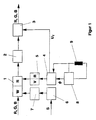
- Figure 1 shows a block diagram with the understanding of the invention essential components of a display device.
- the signals present at the input which are R, G, B signals, are via a storage unit 1, a digital / analog converter 2 and regulated amplifier 3 fed to the screen, not shown.
- the display device shown contains a memory control circuit and one Horizontal deflection circuit.
- the memory control circuit has a read clock 4, a write clock 6 and address counters 5 and 7.
- the address counter 5 contains an up / down counter.
- the horizontal deflection circuit contains a horizontal deflection generator 8 and a horizontal deflection coil 9.
- the Write clock 6 sync pulses converted into a write clock signal, which Address counter 7 controls, so that the writing process in the rhythm of Input signals can take place.
- the horizontal deflection generator 8 provides the at its output Horizontal deflection current available, which of the horizontal deflection coil 8 and the Reading clock 4 is supplied.
- the reading clock 4 is first in one Differentiator from the deflection current formed the time derivative, which is a measure for the speed of the electron beam. This in turn depends on the position of the current sampling point within the current line.
- the reading clock generator 4 receives a signal ⁇ from the horizontal deflection generator 8 supplied which information about the phase position of the horizontal deflection current contains.
- reading clock generator 4 is used for generation of the reading clock signal uses a correction signal, all of which by the geometric properties of the picture tube caused unwanted Imaging effects compensated. For example, the dependence of the length of the Electron beam from the deflection angle or the current position in the current line is taken into account.
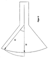
- Figure 2 clearly shows that the length I1 of the electron beam at the edge of the Picture tube is greater than the length I2 in the middle. This results in one different horizontal velocity of the electron beam on the Screen, which makes it necessary to generate a correction signal that this Compensates for effect.
- the reading clock generator 5 generates a from the signals supplied to it Read clock signal, which is variable within the duration of a line to be displayed and inversely proportional to the speed of the electron beam on the Screen is.
- This read clock signal is via the address counter 5, which one Includes up / down counter, the storage unit 1 supplied.
- Such Approach in the line direction achieved an image display with high linearity.
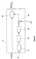
- FIG. 3a shows a block diagram of a first embodiment of the reading clock generator 4 from FIG. 1.
- This contains a differentiating element 41, a rectifier 48, a voltage-controlled oscillator 42 and a pulse shaper 43.
- the deflection current I h is fed to the input of the differentiating element 41. Accordingly, a signal is available at the output of the differentiator 41, which corresponds to the derivative of the deflection current over time.
- this signal drives the voltage-controlled oscillator 42 to generate a signal of a predetermined frequency. This in turn is converted into the reading clock signal in the pulse shaper 43, the pulse shaper 43 also being supplied with the signal ⁇ generated in the horizontal deflection generator, which contains information about the phase position of the horizontal deflection current.
- the signal ⁇ is used to determine the start and stop time of the Define pulse shaper 43 generated signals. That at the output of the reading clock Available reading clock signal is supplied to the address counter 5, the is connected on the output side to the memory 1.
- FIG. 3b shows a block diagram of a second embodiment of the Reading clock 4 of Figure 1.
- This embodiment differs from that in 3a shown in that it also has an A / D converter 44, a Memory table 45, a D / A converter 46 and a multiplier 47 contains.
- the correction signal already mentioned above is obtained generated and superimposed on the output signal of the rectifier 48.
- the output current of the regulated amplifier 3 of FIG. 1 is controlled by means of a voltage signal U f , the voltage of which is proportional to the speed of the electron steel and thus its position. At a high speed (middle of the line), the regulated amplifier 3 thus generates a larger output current than at a low speed (edges of the line).
- the signal U t is formed from the rectified derivation of the deflection current I h , the correction signal described above also being received in FIG. 3b.
- the regulated amplifier 3 has an amplifier 30 controlled by the voltage signal U f , the output current of which drives the cathode and, as explained above, compensates for the differences in luminance caused by the different speed of the electron beam.
- the regulated amplifier 3 has an amplifier 30 controlled by the voltage signal U, a correction circuit formed by a digital / analog converter 31, a memory table 32 and an analog / digital converter 33, and one Multiplier 34, which combines the signal of the correction circuit with the voltage signal U f .
- the output current of this regulated amplifier that drives the cathode equals in addition to that due to the different speed of the Differences in luminance also caused the electron beam Luminance fluctuations of the display tube.
- the signal ⁇ which is the phase position of the horizontal deflection current and thus the position of the Corresponds to the electron beam in the line, the correction signal formed by the for the respective position determined correction value from the memory table 32 is read out.
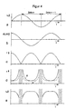
- FIG. 4 shows diagrams for explaining the time course of various Signals from Figure 1.
- FIG. 4a shows the time course of the horizontal deflection current I h over the duration of two successive lines. This horizontal deflection current is fed to the input of the differentiating element 41 shown in FIG. 3a.
- FIG. 4b shows the course of the signal present at the output of the differentiator 41, which corresponds to the time derivative of the horizontal deflection current.
- FIG. 4c shows the frequency signal f provided at the output of the voltage-controlled oscillator 42.
- FIG. 4d shows the read clock signal ⁇ present at the output of the pulse shaper 43, which is fed to the address counter 5 contained in FIG.
- the areas hatched in FIG. 4d indicate the horizontal blanking gaps, during which no read clock signal is generated by the read clock generator. From the course of the signal shown in FIG. 4d, it can be seen that the duration of the reading clock signal ⁇ is the smallest in the middle of a line and increases in the horizontal direction towards both image edges.
- Reading clock generator in which the correction signal is taken into account, then the read clock signal results in that shown in dashed lines in FIG. 4d Signal curve K '. Overall, this is somewhat flatter than the course of the signal K without taking into account the correction signal.
- FIG. 4e finally shows the output current I k of the regulated amplifier 3, which is applied to the cathode.
- the solid lines indicate the course of the output current as it is generated to compensate for the different speed of the electron beam (FIG. 5a).
- the dashed lines give an example of the course of the output current if the luminance fluctuations of the picture tube are additionally compensated for (FIG. 5b).
- the cathode current is raised slightly towards the edges of the picture tube in order to obtain a homogeneous luminance distribution.
- the use of the screen device according to the invention is in addition to Computer technology also for other areas in which a screen display is possible, for example in TV sets.
Landscapes
- Engineering & Computer Science (AREA)
- Signal Processing (AREA)
- Multimedia (AREA)
- Theoretical Computer Science (AREA)
- Computer Hardware Design (AREA)
- General Physics & Mathematics (AREA)
- Physics & Mathematics (AREA)
- Remote Sensing (AREA)
- Radar, Positioning & Navigation (AREA)
- Details Of Television Scanning (AREA)
- Viewfinders (AREA)
- Photoreceptors In Electrophotography (AREA)
- Ultra Sonic Daignosis Equipment (AREA)
Description
Claims (11)
- Bildschirmgerät mitdadurch gekennzeichnet, daß ein geregelter Verstärker (3) zur Erzeugung eines Kathodenstrahistroms vorhanden ist, der den Kathodenstrahlstrom abhängig von der horizontalen Geschwindigkeit des Elektronenstrahls in der darzustellenden Zeile erzeugt, derart daß die Strahlintensität von der Bildschirmmitte zum Rand hin abnimmt.einer Horizontalablenkschaltung mit einem Horizontalablenkgenerator zur Erzeugung eines Ablenkstromes für eine Horizontalablenkspule derart, daß eine symmetrische Ablenkung des Elektronenstrahls erfolgt, bei der sowohl der Hinlauf als auch der Rücklauf zur Signaldarstellung genutzt wird und bei der die Ablenkgeschwindigkeit von der Bildschirmmitte zum Rand hin abnimmt,einer Speichereinheit zur Zwischenspeicherung des darzustellenden Signals, undeiner Speichersteuerschaltung zur Erzeugung des Schreib- und des Lesetaktes für das darzustellende Signal, wobeidie Speichersteuerschaltung einen Lesetaktgenerator (4) zur Erzeugung des Lesetaktes aufweist, welcher den Lesetakt derart erzeugt, daß er innerhalb der Dauer einer darzustellenden Zeile variabel ist,
- Bildschirmgerät nach Anspruch 1,
dadurch gekennzeichnet, daß die Dauer (τ) des Lesetaktes des Lesetaktgenerators (4) umgekehrt proportional zur horizontalen Geschwindigkeit des Elektronenstrahls auf dem Bildschirm ist. - Bildschirmgerät nach Anspruch 1 oder 2,
dadurch gekennzeichnet, daß der geregelte Verstärker (3) den Kathodenstrahlstrom bei einer Verringerung der horizontalen Geschwindigkeit des Elektronenstrahls reduziert. - Bildschirmgerät nach einem der Ansprüche 1 bis 3,
dadurch gekennzeichnet, daß das Bildschirmgerät eine Schaltung aufweist, die ein von der Geschwindigkeit des Elektronenstrahls abhängiges Ausgangssignal (Uf) erzeugt. - Bildschirmgerät nach Anspruch 4,
dadurch gekennzeichnet, daß die Schaltung eine Reihenschaltung aufweist, die ein Differenzierglied (41), einen Gleichrichter (48), der ein von der Geschwindigkeit des Elektronenstrahls abhängiges Ausgangssignal (Uf) erzeugt, einen spannungsgesteuerten Oszillator (42) und einen Pulsformer (43) aufweist. - Bildschirmgerät nach Anspruch 4 oder 5,
dadurch gekennzeichnet, daß die Schaltung eine Zusatzschaltung (44,45,46) zur Erzeugung eines ersten Korrektursignals aufweist. - Bildschirmgerät nach Anspruch 6,
dadurch gekennzeichnet, daß die Zusatzschaltung eine Reihenschaltung aufweist, die einen A/D-Wandler (44), eine Speichertabelle (45) und einen D/A-Wandler (46) enthält, und
daß das Ausgangssignal des D/A-Wandlers (46) und das Ausgangssignal des Gleichrichters (48) mittels eines Multiplizierers (47) zu einem von der Geschwindigkeit und der Position des Elektronenstrahls abhängigen Ausgangssingal (Uf) überlagert werden. - Bildschirmgerät nach einem oder mehreren der Ansprüche 4 bis 7,
dadurch gekennzeichnet, daß das Ausgangssignal (Uf) des Lesetaktgenerators (4) den geregelten Verstärker (3) steuert. - Bildschirmgerät nach Anspruch 8,
dadurch gekennzeichnet, daß der geregelte Verstärker (3) eine Zusatzschaltung (31,32,33) zur Erzeugung eines zweiten Korrektursignals aufweist. - Bildschirmgerät nach Anspruch 9,
dadurch gekennzeichnet, daß die Zusatzschaltung eine Reihenschaltung aufweist, die einen A/D-Wandler (31), eine Speichertabelle (32) und einen D/A-Wandler (33) enthält, und
daß das Ausgangssignal des D/A-Wandlers (33) und das Ausgangssignal (Uf) des Lesetaktgenerators (4) mittels eines Multiplizierers (34) überlagert werden. - Bildschirmgerät nach einem oder mehreren der vorhergehenden Ansprüche,
dadurch gekennzeichnet, daß der Horizontalablenkgenerator (7) zur Erzeugung eines sinusförmigen Ablenkstromes vorgesehen ist.
Applications Claiming Priority (2)
| Application Number | Priority Date | Filing Date | Title |
|---|---|---|---|
| DE19521816A DE19521816C1 (de) | 1995-06-16 | 1995-06-16 | Bildschirmgerät mit gleichmäßiger Leuchtdichte- und Schärfeverteilung |
| DE19521816 | 1995-06-16 |
Publications (3)
| Publication Number | Publication Date |
|---|---|
| EP0749235A2 EP0749235A2 (de) | 1996-12-18 |
| EP0749235A3 EP0749235A3 (de) | 1999-07-28 |
| EP0749235B1 true EP0749235B1 (de) | 2001-11-28 |
Family
ID=7764459
Family Applications (1)
| Application Number | Title | Priority Date | Filing Date |
|---|---|---|---|
| EP96108904A Expired - Lifetime EP0749235B1 (de) | 1995-06-16 | 1996-06-04 | Bildschirmgerät mit symmetrischer Ablenkung |
Country Status (3)
| Country | Link |
|---|---|
| EP (1) | EP0749235B1 (de) |
| AT (1) | ATE209839T1 (de) |
| DE (2) | DE19521816C1 (de) |
Family Cites Families (5)
| Publication number | Priority date | Publication date | Assignee | Title |
|---|---|---|---|---|
| DE3068551D1 (en) * | 1980-10-31 | 1984-08-16 | Ibm | Cathode ray tube drive circuitry |
| US4600945A (en) * | 1983-03-31 | 1986-07-15 | Rca Corporation | Digital video processing system with raster distortion correction |
| DE4207350A1 (de) * | 1992-03-07 | 1993-09-09 | Thomson Brandt Gmbh | Ablenkschaltung fuer einen fernsehempfaenger mit symmetrischer ablenkung |
| EP0598442B1 (de) * | 1992-11-17 | 2003-10-08 | Koninklijke Philips Electronics N.V. | Wiedergabeanordnung mit einer Korrekturschaltung und Korrekturschaltung zum Gebrauch in einer solchen Anordnung |
| DE69607281T2 (de) * | 1995-05-09 | 2000-10-19 | Koninklijke Philips Electronics N.V., Eindhoven | Verbesserung zur helligkeitsuniformität eines bildschirms |
-
1995
- 1995-06-16 DE DE19521816A patent/DE19521816C1/de not_active Expired - Fee Related
-
1996
- 1996-06-04 DE DE59608290T patent/DE59608290D1/de not_active Expired - Fee Related
- 1996-06-04 AT AT96108904T patent/ATE209839T1/de not_active IP Right Cessation
- 1996-06-04 EP EP96108904A patent/EP0749235B1/de not_active Expired - Lifetime
Also Published As
| Publication number | Publication date |
|---|---|
| EP0749235A3 (de) | 1999-07-28 |
| DE59608290D1 (de) | 2002-01-10 |
| EP0749235A2 (de) | 1996-12-18 |
| ATE209839T1 (de) | 2001-12-15 |
| DE19521816C1 (de) | 1996-07-04 |
Similar Documents
| Publication | Publication Date | Title |
|---|---|---|
| DE69325939T2 (de) | Anzeigeeinrichtung zum Anzeigen eines Bildes mit einem anderen Seitenverhältnis | |
| DE69030309T2 (de) | Konvergenzregelsystem für mehrfache vertikale formate | |
| DE3244808C2 (de) | ||
| DE69132409T2 (de) | Einstellbares mehrfachbildanzeigen glättungsverfahren und -gerät | |
| DE3382597T2 (de) | Geraet zur videoaufloesung von graphiken. | |
| DE69228342T3 (de) | Universelle Videoausgangsvorrichtung | |
| DE3134703C2 (de) | ||
| EP0445336B1 (de) | Verfahren und Vorrichtung zur Reduktion des Kantenflackerns eines Fernsehbildes | |
| DE3415348A1 (de) | Anordnung zum herstellen einer photo-, dia- bzw. filmabbildung eines fernsehbildes | |
| DE2252181B2 (de) | Videoverstärker für ein Farbfernsehbildüberwachungsgerät | |
| DE2625347C3 (de) | Vorrichtung zur Wiedergabe von gleichzeitig übertragenen Fernsehsignalen und Symbolsignalen | |
| DE2836582C2 (de) | Fernsehkamera | |
| DE69321438T2 (de) | Anzeigevorrichtung mit Modulation der Abtastgeschwindigkeit | |
| DE69505846T2 (de) | Kathodenstrahlröhrenvorrichtung | |
| DE3801510C2 (de) | ||
| DE2622984C3 (de) | Schaltungsanordnung zur Horizontalaperturkorrektur von Leuchtdichteübergangen eines Videosignals | |
| DE3740782A1 (de) | Fernsehempfaenger mit einer einrichtung zur unterdrueckung von flimmerstoerungen | |
| DE69212799T2 (de) | Kissenverzeichnungskorrekturschaltung für den oberen/unteren Teil | |
| DE69123270T2 (de) | Verfahren und Gerät für spezielle Videoeffekte | |
| DE3411505C2 (de) | ||
| EP1125428A1 (de) | Schaltung zur wandlung einer bildrate | |
| DE3925615C2 (de) | Austastsignal-Schaltung für Fernsehempfänger | |
| DE3786904T2 (de) | Sägezahngenerator. | |
| DE19521816C1 (de) | Bildschirmgerät mit gleichmäßiger Leuchtdichte- und Schärfeverteilung | |
| DE69015388T2 (de) | Fernsehbildanzeigevorrichtung. |
Legal Events
| Date | Code | Title | Description |
|---|---|---|---|
| PUAI | Public reference made under article 153(3) epc to a published international application that has entered the european phase |
Free format text: ORIGINAL CODE: 0009012 |
|
| AK | Designated contracting states |
Kind code of ref document: A2 Designated state(s): AT DE FR GB IT |
|
| RAP1 | Party data changed (applicant data changed or rights of an application transferred) |
Owner name: GRUNDIG AKTIENGESELLSCHAFT |
|
| PUAL | Search report despatched |
Free format text: ORIGINAL CODE: 0009013 |
|
| RIC1 | Information provided on ipc code assigned before grant |
Free format text: 6H 04N 3/30 A |
|
| AK | Designated contracting states |
Kind code of ref document: A3 Designated state(s): AT DE FR GB IT |
|
| 17P | Request for examination filed |
Effective date: 20000113 |
|
| RAP1 | Party data changed (applicant data changed or rights of an application transferred) |
Owner name: GRUNDIG AKTIENGESELLSCHAFT |
|
| GRAG | Despatch of communication of intention to grant |
Free format text: ORIGINAL CODE: EPIDOS AGRA |
|
| 17Q | First examination report despatched |
Effective date: 20010215 |
|
| GRAG | Despatch of communication of intention to grant |
Free format text: ORIGINAL CODE: EPIDOS AGRA |
|
| GRAH | Despatch of communication of intention to grant a patent |
Free format text: ORIGINAL CODE: EPIDOS IGRA |
|
| GRAH | Despatch of communication of intention to grant a patent |
Free format text: ORIGINAL CODE: EPIDOS IGRA |
|
| ITF | It: translation for a ep patent filed | ||
| GRAA | (expected) grant |
Free format text: ORIGINAL CODE: 0009210 |
|
| AK | Designated contracting states |
Kind code of ref document: B1 Designated state(s): AT DE FR GB IT |
|
| REF | Corresponds to: |
Ref document number: 209839 Country of ref document: AT Date of ref document: 20011215 Kind code of ref document: T |
|
| REG | Reference to a national code |
Ref country code: GB Ref legal event code: IF02 |
|
| REF | Corresponds to: |
Ref document number: 59608290 Country of ref document: DE Date of ref document: 20020110 |
|
| GBT | Gb: translation of ep patent filed (gb section 77(6)(a)/1977) |
Effective date: 20020128 |
|
| ET | Fr: translation filed | ||
| PLBE | No opposition filed within time limit |
Free format text: ORIGINAL CODE: 0009261 |
|
| STAA | Information on the status of an ep patent application or granted ep patent |
Free format text: STATUS: NO OPPOSITION FILED WITHIN TIME LIMIT |
|
| 26N | No opposition filed | ||
| REG | Reference to a national code |
Ref country code: GB Ref legal event code: 732E |
|
| REG | Reference to a national code |
Ref country code: FR Ref legal event code: TP |
|
| PGFP | Annual fee paid to national office [announced via postgrant information from national office to epo] |
Ref country code: AT Payment date: 20060608 Year of fee payment: 11 |
|
| PGFP | Annual fee paid to national office [announced via postgrant information from national office to epo] |
Ref country code: FR Payment date: 20060629 Year of fee payment: 11 |
|
| PGFP | Annual fee paid to national office [announced via postgrant information from national office to epo] |
Ref country code: IT Payment date: 20060630 Year of fee payment: 11 |
|
| PGFP | Annual fee paid to national office [announced via postgrant information from national office to epo] |
Ref country code: GB Payment date: 20060706 Year of fee payment: 11 |
|
| PGFP | Annual fee paid to national office [announced via postgrant information from national office to epo] |
Ref country code: DE Payment date: 20060821 Year of fee payment: 11 |
|
| GBPC | Gb: european patent ceased through non-payment of renewal fee |
Effective date: 20070604 |
|
| PG25 | Lapsed in a contracting state [announced via postgrant information from national office to epo] |
Ref country code: AT Free format text: LAPSE BECAUSE OF NON-PAYMENT OF DUE FEES Effective date: 20070604 |
|
| REG | Reference to a national code |
Ref country code: FR Ref legal event code: ST Effective date: 20080229 |
|
| PG25 | Lapsed in a contracting state [announced via postgrant information from national office to epo] |
Ref country code: DE Free format text: LAPSE BECAUSE OF NON-PAYMENT OF DUE FEES Effective date: 20080101 |
|
| PG25 | Lapsed in a contracting state [announced via postgrant information from national office to epo] |
Ref country code: GB Free format text: LAPSE BECAUSE OF NON-PAYMENT OF DUE FEES Effective date: 20070604 |
|
| PG25 | Lapsed in a contracting state [announced via postgrant information from national office to epo] |
Ref country code: FR Free format text: LAPSE BECAUSE OF NON-PAYMENT OF DUE FEES Effective date: 20070702 |
|
| PG25 | Lapsed in a contracting state [announced via postgrant information from national office to epo] |
Ref country code: IT Free format text: LAPSE BECAUSE OF NON-PAYMENT OF DUE FEES Effective date: 20070604 |