EP0748436B1 - Opto-elektronisches skalen-ablese-apparat - Google Patents
Opto-elektronisches skalen-ablese-apparat Download PDFInfo
- Publication number
- EP0748436B1 EP0748436B1 EP95939351A EP95939351A EP0748436B1 EP 0748436 B1 EP0748436 B1 EP 0748436B1 EP 95939351 A EP95939351 A EP 95939351A EP 95939351 A EP95939351 A EP 95939351A EP 0748436 B1 EP0748436 B1 EP 0748436B1
- Authority
- EP
- European Patent Office
- Prior art keywords
- scale
- grating
- analyser
- readhead
- light
- Prior art date
- Legal status (The legal status is an assumption and is not a legal conclusion. Google has not performed a legal analysis and makes no representation as to the accuracy of the status listed.)
- Expired - Lifetime
Links
Images


Classifications
-
- G—PHYSICS
- G01—MEASURING; TESTING
- G01D—MEASURING NOT SPECIALLY ADAPTED FOR A SPECIFIC VARIABLE; ARRANGEMENTS FOR MEASURING TWO OR MORE VARIABLES NOT COVERED IN A SINGLE OTHER SUBCLASS; TARIFF METERING APPARATUS; MEASURING OR TESTING NOT OTHERWISE PROVIDED FOR
- G01D5/00—Mechanical means for transferring the output of a sensing member; Means for converting the output of a sensing member to another variable where the form or nature of the sensing member does not constrain the means for converting; Transducers not specially adapted for a specific variable
- G01D5/26—Mechanical means for transferring the output of a sensing member; Means for converting the output of a sensing member to another variable where the form or nature of the sensing member does not constrain the means for converting; Transducers not specially adapted for a specific variable characterised by optical transfer means, i.e. using infrared, visible, or ultraviolet light
- G01D5/32—Mechanical means for transferring the output of a sensing member; Means for converting the output of a sensing member to another variable where the form or nature of the sensing member does not constrain the means for converting; Transducers not specially adapted for a specific variable characterised by optical transfer means, i.e. using infrared, visible, or ultraviolet light with attenuation or whole or partial obturation of beams of light
- G01D5/34—Mechanical means for transferring the output of a sensing member; Means for converting the output of a sensing member to another variable where the form or nature of the sensing member does not constrain the means for converting; Transducers not specially adapted for a specific variable characterised by optical transfer means, i.e. using infrared, visible, or ultraviolet light with attenuation or whole or partial obturation of beams of light the beams of light being detected by photocells
- G01D5/36—Forming the light into pulses
- G01D5/38—Forming the light into pulses by diffraction gratings
Definitions
- This invention relates to opto-electronic scale reading apparatus.
- Such apparatus may be used with a scale to determine the magnitude and direction of movement of one member relative to another.
- Such an apparatus is typically used to measure the relative movement of two members on coordinate positioning machines such as machine tools or coordinate measuring machines.
- an elongate scale which can be fitted to one of the above members comprises a series of marks, in the form of parallel lines, spaced apart in the longitudinal direction of the scale.
- a readhead for attachment to the other of the members includes an index grating and an analyser grating. Light reflected from (or transmitted through) the scale interacts with the index grating, and causes the generation of a fringe pattern in the plane of the analyser grating.
- this fringe pattern moves in a corresponding fashion in the plane of the analyser grating, and photodetectors situated behind the analyser grating receive a modulated light signal, from which the distance and direction moved can be determined.
- US 4,959,542 provides a spatial filtering effect which ensures that the readhead is very tolerant of defects in the scale or dirt which may accumulate on the scale.
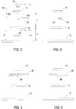
- Fig 1 of the accompanying drawings shows a sensitivity curve S illustrating how the amplitude A of the signal output from the readhead varies with the offset or ride height h of the readhead above the scale. It will be seen that a strong, usable signal is obtained only within a relatively narrow tolerance band T. When the scale and readhead is installed on a machine, therefore, it is necessary to ensure that the readhead will remain within this tolerance band T throughout the length of its travel along the scale.
- British Patent No. 1,474,049 shows scales and readheads of a type which is different from those discussed above.
- light passes from a first grating to a second grating, which reflects it back to the first grating.
- the second grating is tilted with respect to the first grating so that the return optical path from the second grating to the first is greater than the outward optical path from the first grating to the second.
- US Patent No. 4,636,076 shows a development, in which the return optical path differs from the outward optical path by virtue of the light passing through different thicknesses of a material having a refractive index different from the ambient medium.
- these two patents do not address the problems with which the present invention is concerned.
- EP-387520-A, DE-3905838-A and DE-2605670-A show scales and readheads which have different optical paths between gratings, but which operate on different principles to the present invention and do not address the same problems.
- the present invention provides scale and readhead apparatus, in accordance with claims 1 and 4.
- Fig 3 shows a scale 10, index grating 12, analyser grating 14 and one or more photodetectors 16.
- the scale comprises a series of marks, in the form of parallel lines, spaced apart in the longitudinal direction of the scale.
- the index and analyser gratings 12,14 and the photodetectors 16 are provided as a unit in a readhead 18 (-together with a lens and a light source for illuminating the scale, neither of which is shown).
- the arrangement is generally as disclosed in US Patent No. 4,959,542.
- the spacings between the scale, index grating and analyser are related to the pitches of the marks or lines of these optical elements by certain formulae. This causes the light reflected from the marks on the scale to interact with the index grating to form fringes in the plane of the analyser grating. These fringes move in accordance with relative longitudinal movement between the scale and the readhead, and this can be detected in several ways.
- the analyser may be slightly skewed relative to the index grating, within its own plane (which still remains parallel to the index grating).
- the fringes formed in the plane of the analyser then in turn interact with the analyser to generate moiré fringes.
- the analyser 14 and photodetectors 16 may be combined and provided on a single semiconductor substrate in the form of an electrograting, as described in European Patent Application No. EP 543513.
- an electrograting comprises a linear array of narrow, finely spaced photodetectors which take the place of a conventional grating. Interdigitated sets of the photodetectors are each connected in common to provide the required output signals.
- the electrograting may also include integral light sources, or a separate light source may be provided. A lens in the readhead is not necessary.
- the readhead 18 rides at a height h above the scale 10 as it travels longitudinally along the scale in the direction indicated by arrows 20. If the readhead 18 consisted only of the gratings 12,14 and detectors 16 as described thus far, then it would be fairly intolerant of changes in this ride height h as shown in Fig 1 and discussed above.
- Fig 3 shows a plate 22 of a transparent refractive medium inserted between the index grating 12 and the analyser grating 14.
- this plate 22 covers only half of the working area or aperture of the analyser grating 14, as seen also in the plan view of Fig 19. Because it has a different refractive index from the surrounding air, the plate 22 means that the optical path length between the scale 10 and the analyser 14 on the right hand side of the analyser (as seen in Figs 3 and 19) differs from that on the left hand side.
- the plane 15A of the fringes formed by the interaction between the scale and the index grating on the right hand side of these figures differs from the plane 15B of the corresponding fringes on the left hand side.
- the photodetector or photodetectors 16 should have a width (in the longitudinal direction) sufficient to straddle both of the optical paths, so as to detect the light signals from the fringes in both optical paths in common and produce an output signal which combines the light signals.
- the detectors should not be so wide as to be unable to distinguish these moire fringes.
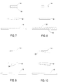
- Fig 4 shows an alternative arrangement, in which the refractive plate 22 is provided with a step in a region 24.
- the refractive plate 22 is provided with a step in a region 24.
- Fig 5 shows another arrangement.
- the plate 22 extends across the entire width of the analyser grating 14, but has a castellated profile 26.
- Fig 6 shows a similar arrangement, but with an undulating or ribbed profile 28.
- the castellations or ribs should have a pitch much greater than the scale and the gratings 12,14, to prevent diffraction and interference effects.
- Fig 7 shows an alternative, in which a refractive medium 30 having a varying thickness is deposited over the surface of the analyser 14.
- a coating 30 may be provided over a conventional analyser grating.
- Fig 8 shows that a refractive medium of varying thickness may instead be deposited on the surface of the scale 10.
- the undulations in the thickness of the refractive medium 30,32 should be on a much larger scale than the pitch of the scale and the gratings, to avoid diffraction and interference effects.
- Fig 9 shows an alternative in which the substrate of the index grating 12 is formed with steps 34, giving the same effect as the insertion of the plate 22 in Figs 3 and 4. There may be any suitable number of such steps 34.
- Fig 10 shows how the same effect can be achieved by having an index grating substrate which is wedge-shaped, i.e. having a continually varying thickness instead of a stepped thickness. This results in a fringe plane 15 which is tilted with respect to the analyser 14. For different ride heights, a different point on the analyser 14 will coincide with the plane 15 of the fringes.
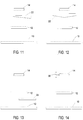
- Fig 11 shows a similar arrangement, but using a wedge-shaped refractive plate 22 between the index grating 12 and the analyser grating 14.
- Fig 12 shows the same arrangement, but the plate 22 is now in the form of a biprism or double wedge.
- Fig 3 it is possible to insert the plate 22 of Fig 3 between the scale 10 and the index grating 12 instead of between the index grating 12 and the analyser 14. This is illustrated in Fig 13. Any of the plates 22 shown in Figs 4,5,6,11 or 12 may similarly be inserted between the scale 10 and the index grating 12. The effect is to vary the optical length u (Fig 3) instead of the optical length v.
- Fig 14 shows another embodiment.
- the analyser 14 is instead vibrated or oscillated towards and away from the index grating 12, as indicated by the arrows 36.
- the vibration may be achieved by, for example, a small motor or a piezoelectric actuator.
- the frequency of the vibration should be substantially higher than the frequency of the light modulations produced by the movement of the scale relative to the readhead, so that the signals over one or more cycles of the vibration can be integrated (e.g. by a suitable filter circuit). This ensures that the light signals from the different optical path lengths (i.e. at different times) are detected in common, as previously.
- the effect of this vibration is that the single sensitivity peak S (and the corresponding tolerance band T) in Fig 1 vibrates in the horizontal direction of that Figure, giving an effective broadening of the ride heights h to which the readhead is responsive.
- Figs 15-17 illustrate further embodiments.
- an optical path length ratio u/v which varies gradually from the left hand side to the right hand side of the analyser is achieved by deliberately tilting one of the elements so that its plane is no longer parallel to the others.
- Fig 15 the analyser 14 is tilted. At one ride height of the readhead above the scale, fringes will formed in the plane 15C; while at another ride height they will be formed in the plane 15D. These and similar planes each coincide with a different point on the tilted analyser, so that good signals can be produced from the region around the point of coincidence for various different ride heights.
- Fig 16 the index grating 12 is tilted. This results in the plane 15 of the fringes also being tilted. Again, for different ride heights, a different point on the analyser 14 will coincide with the plane 15 of the fringes. A similar effect is achieved in Fig 17, in which the scale 10 is tilted. The tilting of the scale 10 in Fig 17 may in practice be most conveniently achieved by tilting the entire readhead relative to the scale.
- Figs 4-17 the photodetector or photodetectors have been omitted for simplicity. However, it will be understood that, as in Fig 3, they may be provided behind the analyser grating 14, or alternatively an electrograting may be used as the analyser 14. The above comments about detecting the signals from the various optical paths in common should be observed.
- the index grating 12 is provided on the underside of a beam splitter cube 38.
- Two separate analyser gratings (and the corresponding detectors) or two separate electrogratings 14A, 14B are provided, respectively receiving the split beams produced by the beam splitter 38.
- the detectors of the analysers 14A, 14B are connected to the signal processing circuit of the readhead in parallel, to detect the light signals in common.
- one of the analysers 14B may be located further from the centre of the cube than the other analyser 14A.
- the optical path difference can be accentuated by inserting a layer 40 of a refractive medium such as glass before the analyser 14B. This layer 40 may suitably be formed on the surface of the cube 38.
- Fig 19 shows how the plate 22 of Fig 3 covers the analyser grating 14 for only part of its longitudinal extent. Nevertheless, it is equally possible for the optical path length to vary with the transverse position, instead of the longitudinal position.
- Fig 20 is a plan view of a modification of the arrangement of Figs 3 and 19.
- the refractive plate 22 in Fig 20 is inserted between the scale 10 and the analyser grating 14 in such a manner as to cover the grating 14 for only part of its transverse extent, rather than for part of its longitudinal extent.
- the arrangements of Figs 4-13 and 15-18 may be modified similarly.
- the steps, castellations and ribs of Figs 4-9, the wedge profiles of Figs 10-12, and the beam splitter of Fig 18, may each be turned through 90°.
- Figs 15-17 it will be appreciated that the required tilting was shown as the deliberate introduction of a pitch angle between the tilted element and the other elements, giving the variation in optical path length in the longitudinal direction. It will be understood that the optical path length may be made to vary in the transverse direction by introducing a deliberate roll angle to the appropriate element instead of a deliberate pitch angle.
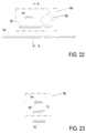
- Figs 22-23 One example of this is illustrated in Figs 22-23.
- the index grating 12 is tilted with a suitable roll angle, producing fringes in a tilted plane 15.
- the analyser 14 is an electrograting according to EP 543513.
- a separate light source 50 is provided, in the form of an infra-red light emitting diode. This could illuminate the scale 10 directly, as in the other embodiments, but for convenience of design and manufacture it is arranged to illuminate it via the index grating 12. By locating the light source close to the index grating it is possible to prevent fringes from forming on the scale itself. It will be seen from Fig 22 that the light source 50 provides the illumination obliquely from one end. This is ideal when the scale has a profile as shown in US Patent No. 4,974,962, where the scale marks have facets which reflect the light vertically towards the index grating 12 and analyser 14.
- Fig 21 shows yet another embodiment. Like Fig 14, the optical path length is here varied by moving the analyser grating 14 towards and away from the scale 10. Thus, there are different optical paths at different times, instead of in different regions. Rather than the continuous vibration of Fig 14, however, the optical path length is varied by a servo loop.
- the outputs from the detectors 16 are processed in a signal processing circuit-42, which (amongst other outputs) produces an output 44 which varies with the amplitude or intensity of the outputs from the detectors 16.
- This output may be produced by rectifying and smoothing the relevant output signals, and combining them together. Alternatively, it may be produced by rectifying and smoothing the outputs of just one of the detectors 16.
- the signal 44 is used to control a servo driver and motor 46, which adjusts the position of the analyser grating 14 in such a manner as to tend to keep the output signals from the detectors 16 at maximum amplitude or intensity.
- the effect will be that, if for example the ride height h between the readhead and the scale 10 decreases then the analyser grating 14 will move closer to the index grating 12 to compensate. This action will tend to keep the spacings between the scale, the index and the analyser gratings in accordance with the desirable relationships explained in US 4,959,542.
Landscapes
- Physics & Mathematics (AREA)
- General Physics & Mathematics (AREA)
- Optical Transform (AREA)
- Character Input (AREA)
- Sorting Of Articles (AREA)
- Inspection Of Paper Currency And Valuable Securities (AREA)
- Measuring Pulse, Heart Rate, Blood Pressure Or Blood Flow (AREA)
- Investigating Or Analysing Materials By Optical Means (AREA)
- Length Measuring Devices By Optical Means (AREA)
Claims (9)
- Optoelektronische Skalen- und Lesekopfvorrichtung mit:dadurch gekennzeichnet, daß zumindest zwei optische Wege vorgesehen sind, die verschiedene optische Weglängen von der Skala zu dem Indexgitter und/oder von dem Indexgitter zu dem Analysegitter aufweisen; und daß für eine erste gegebene Laufhöhe des Lesekopfes über der Skala Interferenzstreifen, die durch Licht bewirkt werden, das entlang eines der optischen Wege läuft, mit dem Analysegitter übereinstimmen, während für eine zweite gegebene Laufhöhe des Lesekopfes über der Skala Interferenzstreifen, die durch Licht bewirkt werden, das entlang eines anderen der optischen Wege läuft, mit dem Analysegitter übereinstimmen.einer länglichen Skala, die durch eine Serie von Markierungen definiert ist, die in Längsrichtung voneinander beabstandet sind;einem Lesekopf, der sich in der Längsrichtung der Skala von dieser um eine Laufhöhe beabstandet bewegt, wobei der Lesekopf ein Indexgitter und ein Analysegitter umfaßt, und Licht, das von der Skala kommt, mit dem Indexgitter in Wechselwirkung tritt, wodurch Interferenzstreifen in der Nähe des Analysegitters zur Analyse durch das Analysegitter erzeugt werden;
- Vorrichtung nach Anspruch 1, mit zumindest einem Photodetektor, der zur gemeinsamen Detektion von Licht von den verschiedenen optischen Wegen angeordnet ist.
- Vorrichtung nach Anspruch 1 oder Anspruch 2, wobei das Analysegitter in der Form einer Halbleitervorrichtung vorliegt, die mehrere Photodetektoren umfaßt.
- Optoelektronische Skalen- und Lesekopfvorrichtung, mit einer Lichtquelle, zumindest einem Photodetektor und zumindest drei optischen Elementen, die in Serie in dem Weg des Lichtes von der Lichtquelle zu dem zumindest einem Photodetektor angeordnet sind,gekennzeichnet durchwobei eines der optischen Elemente eine längliche Skala umfaßt, die durch eine Serie von Markierungen definiert ist, die voneinander in Längsrichtung beabstandet sind;die anderen beiden der optischen Elemente ein Indexgitter und ein Analysegitter umfassen, die an dem zumindest einen Photodetektor in einem Lesekopf zur Bewegung in der Längsrichtung der Skala befestigt sind,zumindest zwei alternative optische Wege für das Licht zwischen den drei optischen Elementen, wobei sich das Verhältnis u/v in einem der optischen Wege von dem Verhältnis u/v in einem anderen der optischen Wege unterscheidet, wobei u die optische Weglänge des Lichtes von einem ersten der optischen Elemente zu einem zweiten der optischen Elemente und v die optische Weglänge des Lichtes von dem zweiten der optischen Elemente zu einem dritten der optischen Elemente ist,wobei der zumindest eine Photodetektor Interferenzstreifen, die durch Licht in einem der optischen Wege erzeugt werden, gemeinsam mit Interferenzstreifen detektiert, die durch Licht in einem anderen der optischen Wege erzeugt werden.
- Vorrichtung nach Anspruch 4, wobei das Analysegitter in der Form einer Halbleitervorrichtung vorliegt und mehrere Photodetektoren umfaßt.
- Vorrichtung nach einem der Ansprüche 1 bis 5, wobei ein Element aus einem transparenten refraktives Material in zumindest einem der optischen Wege angeordnet ist, um in den optischen Wegen verschiedene optische Weglängen zu schaffen.
- Vorrichtung nach Anspruch 6, wobei das refraktive Element in verschiedenen optischen Wege eine verschiedene Dicke aufweist.
- Vorrichtung nach einem der Ansprüche 1 bis 5, wobei eines der Elemente Skala, Indexgitter und Analysegitter so geneigt ist, daß dieses zu den anderen nicht parallel angeordnet ist, um in den optischen Wegen verschiedene optische Weglängen zu schaffen.
- Vorrichtung nach Anspruch 8, wobei das Indexgitter so geneigt ist, daß es zu der Skala und dem Analysegitter nicht parallel ist, um die verschiedenen optischen Weglängen zu schaffen.
Applications Claiming Priority (3)
| Application Number | Priority Date | Filing Date | Title |
|---|---|---|---|
| GBGB9424969.5A GB9424969D0 (en) | 1994-12-10 | 1994-12-10 | Opto-electronic scale reading apparatus |
| GB9424969 | 1994-12-10 | ||
| PCT/GB1995/002864 WO1996018868A1 (en) | 1994-12-10 | 1995-12-08 | Opto-electronic scale reading apparatus |
Publications (2)
| Publication Number | Publication Date |
|---|---|
| EP0748436A1 EP0748436A1 (de) | 1996-12-18 |
| EP0748436B1 true EP0748436B1 (de) | 2000-08-30 |
Family
ID=10765744
Family Applications (1)
| Application Number | Title | Priority Date | Filing Date |
|---|---|---|---|
| EP95939351A Expired - Lifetime EP0748436B1 (de) | 1994-12-10 | 1995-12-08 | Opto-elektronisches skalen-ablese-apparat |
Country Status (6)
| Country | Link |
|---|---|
| US (1) | US5861953A (de) |
| EP (1) | EP0748436B1 (de) |
| AT (1) | ATE196004T1 (de) |
| DE (1) | DE69518630T2 (de) |
| GB (1) | GB9424969D0 (de) |
| WO (1) | WO1996018868A1 (de) |
Families Citing this family (27)
| Publication number | Priority date | Publication date | Assignee | Title |
|---|---|---|---|---|
| GB9924331D0 (en) * | 1999-10-15 | 1999-12-15 | Renishaw Plc | Scale reading apparatus |
| GB0004120D0 (en) * | 2000-02-23 | 2000-04-12 | Renishaw Plc | Opto-electronic scale reading apparatus |
| WO2006054255A1 (en) * | 2004-11-22 | 2006-05-26 | Koninklijke Philips Electronics N.V. | Optical system for detecting motion of a body |
| GB0608812D0 (en) * | 2006-05-04 | 2006-06-14 | Renishaw Plc | Rotary encoder apparatus |
| EP2058630A1 (de) | 2007-11-12 | 2009-05-13 | FAGOR, S.Coop. | Lesekopf für ein optoelektronisches Messgerät |
| EP2226613B1 (de) * | 2009-03-02 | 2011-02-16 | Fagor, S. Coop. | Lesekopf für ein optisches Positionsmessgerät |
| US8772706B2 (en) * | 2012-04-20 | 2014-07-08 | Mitutoyo Corporation | Multiple wavelength configuration for an optical encoder readhead including dual optical path region with an optical path length difference |
| GB201301186D0 (en) | 2012-12-20 | 2013-03-06 | Renishaw Plc | Optical element |
| EP3052896A1 (de) | 2013-10-01 | 2016-08-10 | Renishaw Plc. | Positionsmessungscodierer |
| WO2015049174A1 (en) | 2013-10-01 | 2015-04-09 | Renishaw Plc | Measurement encoder |
| JP6811610B2 (ja) | 2013-10-01 | 2021-01-13 | レニショウ パブリック リミテッド カンパニーRenishaw Public Limited Company | 電子コンポーネントを製造する方法 |
| WO2015049173A1 (en) | 2013-10-01 | 2015-04-09 | Renishaw Plc | Reference mark detector arrangement |
| WO2015067506A1 (en) | 2013-11-05 | 2015-05-14 | Renishaw Plc | Position measurement encoder calibration |
| WO2015078860A1 (en) | 2013-11-26 | 2015-06-04 | Renishaw Plc | Metrological scale |
| DE102015209716B4 (de) * | 2014-05-29 | 2023-04-20 | Mitutoyo Corporation | Optischer Codierer mit anpassbarer Auflösung |
| NL2015639A (en) * | 2014-11-28 | 2016-09-20 | Asml Netherlands Bv | Encoder, position measurement system and lithographic apparatus. |
| EP3347681B1 (de) | 2015-09-09 | 2020-09-02 | Renishaw Plc. | Codierervorrichtung |
| GB201916641D0 (en) | 2019-11-15 | 2020-01-01 | Renishaw Plc | Position measurement device |
| GB201916662D0 (en) | 2019-11-15 | 2020-01-01 | Renishaw Plc | Encoder apparatus |
| JP2024532808A (ja) | 2021-08-12 | 2024-09-10 | レニショウ パブリック リミテッド カンパニー | ポジションエンコーダ装置 |
| EP4134633A1 (de) | 2021-08-12 | 2023-02-15 | Renishaw PLC | Positionscodierer |
| WO2024134153A1 (en) | 2022-12-20 | 2024-06-27 | Renishaw Plc | Encoder apparatus |
| EP4390326A1 (de) | 2022-12-20 | 2024-06-26 | Renishaw PLC | Kodiergerät |
| EP4390327A1 (de) | 2022-12-20 | 2024-06-26 | Renishaw PLC | Kodiergerät |
| EP4390325A1 (de) | 2022-12-20 | 2024-06-26 | Renishaw PLC | Kodiergerät |
| EP4414664A1 (de) | 2023-02-09 | 2024-08-14 | Renishaw PLC | Rotierende kodiervorrichtung |
| EP4484898A1 (de) | 2023-06-29 | 2025-01-01 | Renishaw PLC | Kodiergerät |
Family Cites Families (10)
| Publication number | Priority date | Publication date | Assignee | Title |
|---|---|---|---|---|
| GB1474049A (en) * | 1974-01-12 | 1977-05-18 | Leitz Ernst Gmbh | Arrangement for the modulation of light |
| DE2605670A1 (de) * | 1976-02-13 | 1977-08-18 | Zeiss Carl Fa | Einrichtung zur erzeugung phasenverschobener elektrischer signale |
| DE3322738C1 (de) * | 1983-06-24 | 1984-10-18 | Dr. Johannes Heidenhain Gmbh, 8225 Traunreut | Lichtelektrische Längen- oder Winkelmeßeinrichtung |
| GB8320629D0 (en) * | 1983-07-30 | 1983-09-01 | Pa Consulting Services | Displacement measuring apparatus |
| GB8432574D0 (en) * | 1984-12-22 | 1985-02-06 | Renishaw Plc | Opto-electronic scale-reading apparatus |
| GB8616240D0 (en) * | 1986-07-03 | 1986-08-13 | Renishaw Plc | Opto-electronic scale reading apparatus |
| DE3872227T2 (de) * | 1987-12-15 | 1992-12-03 | Renishaw Plc | Opto-elektronischer skalenlese-apparat. |
| US4979827A (en) * | 1988-02-26 | 1990-12-25 | Kabushiki Kaisha Okuma Tekkosho | Optical linear encoder |
| DE3905730C2 (de) * | 1989-02-24 | 1995-06-14 | Heidenhain Gmbh Dr Johannes | Positionsmeßeinrichtung |
| EP0843159A3 (de) * | 1991-11-06 | 1999-06-02 | Renishaw Transducer Systems Limited | Opto-elektronischer Skalenableseapparat |
-
1994
- 1994-12-10 GB GBGB9424969.5A patent/GB9424969D0/en active Pending
-
1995
- 1995-12-08 WO PCT/GB1995/002864 patent/WO1996018868A1/en not_active Ceased
- 1995-12-08 AT AT95939351T patent/ATE196004T1/de active
- 1995-12-08 DE DE69518630T patent/DE69518630T2/de not_active Expired - Lifetime
- 1995-12-08 US US08/687,496 patent/US5861953A/en not_active Expired - Lifetime
- 1995-12-08 EP EP95939351A patent/EP0748436B1/de not_active Expired - Lifetime
Also Published As
| Publication number | Publication date |
|---|---|
| EP0748436A1 (de) | 1996-12-18 |
| US5861953A (en) | 1999-01-19 |
| GB9424969D0 (en) | 1995-02-08 |
| ATE196004T1 (de) | 2000-09-15 |
| WO1996018868A1 (en) | 1996-06-20 |
| DE69518630T2 (de) | 2001-01-11 |
| DE69518630D1 (de) | 2000-10-05 |
Similar Documents
| Publication | Publication Date | Title |
|---|---|---|
| EP0748436B1 (de) | Opto-elektronisches skalen-ablese-apparat | |
| US4943716A (en) | Diffraction-type optical encoder with improved detection signal insensitivity to optical grating gap variations | |
| JP5100266B2 (ja) | エンコーダ | |
| US7435945B2 (en) | Optical configuration for imaging-type optical encoders | |
| KR100231388B1 (ko) | 광헤드의 트래킹오차 검출장치(Optical Head Tracking Error Detection Device) | |
| JP2501714B2 (ja) | 干渉位置測定装置 | |
| JP3121539B2 (ja) | 光電位置測定装置 | |
| JP6161240B2 (ja) | 変位センサ | |
| US5214280A (en) | Photoelectric position detector with offset phase grating scales | |
| US6771377B2 (en) | Optical displacement sensing device with reduced sensitivity to misalignment | |
| US4979827A (en) | Optical linear encoder | |
| JP2818800B2 (ja) | 位置に依存する信号を発生する装置 | |
| US6723980B2 (en) | Position sensor with grating to detect moving object with periodic pattern | |
| JP2005526951A (ja) | 基準点タルボットエンコーダ | |
| JP2000230803A (ja) | 光学的位置測定装置 | |
| JPH095026A (ja) | 光電位置測定装置 | |
| JPH0933212A (ja) | 位置測定装置 | |
| US5033817A (en) | Scale for use with opto-electronic scale reading apparatus | |
| US5184014A (en) | Opto-electronic scale reading apparatus | |
| WO1990013006A1 (en) | Opto-electronic scale-reading apparatus | |
| JP7522671B2 (ja) | 光学式エンコーダ | |
| JPH09126818A (ja) | 光電測長または測角装置 | |
| JP2715623B2 (ja) | エンコーダ | |
| JP4401852B2 (ja) | 光学式変位測定装置 | |
| JP7523866B2 (ja) | 光学式エンコーダ |
Legal Events
| Date | Code | Title | Description |
|---|---|---|---|
| PUAI | Public reference made under article 153(3) epc to a published international application that has entered the european phase |
Free format text: ORIGINAL CODE: 0009012 |
|
| 17P | Request for examination filed |
Effective date: 19960729 |
|
| AK | Designated contracting states |
Kind code of ref document: A1 Designated state(s): AT DE GB IT |
|
| 17Q | First examination report despatched |
Effective date: 19990215 |
|
| GRAG | Despatch of communication of intention to grant |
Free format text: ORIGINAL CODE: EPIDOS AGRA |
|
| GRAG | Despatch of communication of intention to grant |
Free format text: ORIGINAL CODE: EPIDOS AGRA |
|
| GRAH | Despatch of communication of intention to grant a patent |
Free format text: ORIGINAL CODE: EPIDOS IGRA |
|
| GRAH | Despatch of communication of intention to grant a patent |
Free format text: ORIGINAL CODE: EPIDOS IGRA |
|
| GRAA | (expected) grant |
Free format text: ORIGINAL CODE: 0009210 |
|
| ITF | It: translation for a ep patent filed | ||
| AK | Designated contracting states |
Kind code of ref document: B1 Designated state(s): AT DE GB IT |
|
| REF | Corresponds to: |
Ref document number: 196004 Country of ref document: AT Date of ref document: 20000915 Kind code of ref document: T |
|
| REF | Corresponds to: |
Ref document number: 69518630 Country of ref document: DE Date of ref document: 20001005 |
|
| EN | Fr: translation not filed | ||
| PLBE | No opposition filed within time limit |
Free format text: ORIGINAL CODE: 0009261 |
|
| STAA | Information on the status of an ep patent application or granted ep patent |
Free format text: STATUS: NO OPPOSITION FILED WITHIN TIME LIMIT |
|
| 26N | No opposition filed | ||
| REG | Reference to a national code |
Ref country code: GB Ref legal event code: IF02 |
|
| PGFP | Annual fee paid to national office [announced via postgrant information from national office to epo] |
Ref country code: IT Payment date: 20121221 Year of fee payment: 18 |
|
| PGFP | Annual fee paid to national office [announced via postgrant information from national office to epo] |
Ref country code: AT Payment date: 20121212 Year of fee payment: 18 |
|
| PGFP | Annual fee paid to national office [announced via postgrant information from national office to epo] |
Ref country code: DE Payment date: 20121220 Year of fee payment: 18 |
|
| REG | Reference to a national code |
Ref country code: DE Ref legal event code: R119 Ref document number: 69518630 Country of ref document: DE |
|
| REG | Reference to a national code |
Ref country code: AT Ref legal event code: MM01 Ref document number: 196004 Country of ref document: AT Kind code of ref document: T Effective date: 20131208 |
|
| REG | Reference to a national code |
Ref country code: DE Ref legal event code: R119 Ref document number: 69518630 Country of ref document: DE Effective date: 20140701 |
|
| PG25 | Lapsed in a contracting state [announced via postgrant information from national office to epo] |
Ref country code: DE Free format text: LAPSE BECAUSE OF NON-PAYMENT OF DUE FEES Effective date: 20140701 |
|
| PG25 | Lapsed in a contracting state [announced via postgrant information from national office to epo] |
Ref country code: AT Free format text: LAPSE BECAUSE OF NON-PAYMENT OF DUE FEES Effective date: 20131208 |
|
| PGFP | Annual fee paid to national office [announced via postgrant information from national office to epo] |
Ref country code: GB Payment date: 20141219 Year of fee payment: 20 |
|
| REG | Reference to a national code |
Ref country code: GB Ref legal event code: PE20 Expiry date: 20151207 |
|
| PG25 | Lapsed in a contracting state [announced via postgrant information from national office to epo] |
Ref country code: GB Free format text: LAPSE BECAUSE OF EXPIRATION OF PROTECTION Effective date: 20151207 |
|
| PG25 | Lapsed in a contracting state [announced via postgrant information from national office to epo] |
Ref country code: IT Free format text: LAPSE BECAUSE OF NON-PAYMENT OF DUE FEES Effective date: 20131208 |