EP0747548B1 - Dispositif pour l'assemblage de sections - Google Patents
Dispositif pour l'assemblage de sections Download PDFInfo
- Publication number
- EP0747548B1 EP0747548B1 EP96850084A EP96850084A EP0747548B1 EP 0747548 B1 EP0747548 B1 EP 0747548B1 EP 96850084 A EP96850084 A EP 96850084A EP 96850084 A EP96850084 A EP 96850084A EP 0747548 B1 EP0747548 B1 EP 0747548B1
- Authority
- EP
- European Patent Office
- Prior art keywords
- locking tongue
- arrangement
- main section
- section
- connecting hole
- Prior art date
- Legal status (The legal status is an assumption and is not a legal conclusion. Google has not performed a legal analysis and makes no representation as to the accuracy of the status listed.)
- Expired - Lifetime
Links
- 210000002105 tongue Anatomy 0.000 claims description 98
- 238000005452 bending Methods 0.000 description 5
- 230000006978 adaptation Effects 0.000 description 1
- 239000011324 bead Substances 0.000 description 1
- 210000003811 finger Anatomy 0.000 description 1
- 239000002184 metal Substances 0.000 description 1
- 238000004080 punching Methods 0.000 description 1
- 230000002787 reinforcement Effects 0.000 description 1
- 239000000725 suspension Substances 0.000 description 1
- 210000003813 thumb Anatomy 0.000 description 1
Images


Classifications
-
- E—FIXED CONSTRUCTIONS
- E04—BUILDING
- E04B—GENERAL BUILDING CONSTRUCTIONS; WALLS, e.g. PARTITIONS; ROOFS; FLOORS; CEILINGS; INSULATION OR OTHER PROTECTION OF BUILDINGS
- E04B9/00—Ceilings; Construction of ceilings, e.g. false ceilings; Ceiling construction with regard to insulation
- E04B9/06—Ceilings; Construction of ceilings, e.g. false ceilings; Ceiling construction with regard to insulation characterised by constructional features of the supporting construction, e.g. cross section or material of framework members
- E04B9/12—Connections between non-parallel members of the supporting construction
- E04B9/122—Connections between non-parallel members of the supporting construction one member passing through the other member, both members laying at least partly in the same plane
-
- F—MECHANICAL ENGINEERING; LIGHTING; HEATING; WEAPONS; BLASTING
- F16—ENGINEERING ELEMENTS AND UNITS; GENERAL MEASURES FOR PRODUCING AND MAINTAINING EFFECTIVE FUNCTIONING OF MACHINES OR INSTALLATIONS; THERMAL INSULATION IN GENERAL
- F16B—DEVICES FOR FASTENING OR SECURING CONSTRUCTIONAL ELEMENTS OR MACHINE PARTS TOGETHER, e.g. NAILS, BOLTS, CIRCLIPS, CLAMPS, CLIPS OR WEDGES; JOINTS OR JOINTING
- F16B7/00—Connections of rods or tubes, e.g. of non-circular section, mutually, including resilient connections
- F16B7/04—Clamping or clipping connections
- F16B7/044—Clamping or clipping connections for rods or tubes being in angled relationship
- F16B7/048—Clamping or clipping connections for rods or tubes being in angled relationship for rods or for tubes without using the innerside thereof
- F16B7/0486—Clamping or clipping connections for rods or tubes being in angled relationship for rods or for tubes without using the innerside thereof forming an abutting connection of at least one tube
Definitions
- the present invention relates to an arrangement for connecting at least one transverse section and a main section in a system of sections, especially for supporting suspended ceilings, said arrangement comprising a projecting locking tongue arranged on the end of the transverse section and having a laterally projecting hook member and, formed in the main section, a connecting hole for receiving said locking tongue, the locking tongue being arranged to be laterally resilient during the connecting operation when being inserted into the connecting hole and during the disconnecting operation when being withdrawn from the connecting hole, thereby allowing the hook member to pass through the connecting hole into locking engagement on the opposite side of the main section, and to pass from such locking engagement and back through the connecting hole, respectively.
- the locking tongue has a double function by serving as guide means as well as locking means, the hook member arranged thereon being adapted to cooperate with the main section or with a second locking tongue arranged from the opposite direction and belonging to a second transverse section.
- the rigidity of the locking tongue is considerable, in many cases by the locking tongue being formed with embossed portions, longitudinal beads or the like. As will be appreciated, this affects the resilience of the locking tongue in a negative way, which makes it difficult to mount and dismount a transverse section. Moreover a remaining deformation of the locking tongue often arises when bending it laterally outwards, as is required in mounting and dismounting. Such deformation is, of course, disadvantageous and may cause, among other things, an inaccurate positioning of the associated transverse section.
- a further problem is that prior-art designs of the locking tongues in many cases involve such a length of the locking tongues that after mounting in a main section, they protrude significantly on the side of the main section facing away from the mounted transverse section. This is particularly unfavourable when a single transverse section is to be connected, i.e. when there is no second transverse section aligned with the first transverse section on the opposite side of the main section.
- the object of the invention is to eliminate the above described problems to a considerable degree and to provide
- the invention thus is based on the knowledge that substantial advantages can be achieved by the locking and guiding functions of the transverse section being separated.
- separate free-standing guide means are arranged on the end of the transverse section for cooperating with the main section so as to give the transverse section and the main section a well defined, fixed relative position when connected.
- the guide means can be designed exclusively to have a good guiding function, i.e. they can be designed without resilience requirements etc. needing be complied with, at the same time as the locking tongue can be designed with the aim of giving good resilience with no risk of remaining deformations when being bent laterally outwards.
- each individual transverse section can be very accurately positioned relative to the main section, i.e. independently of whether the transverse section is to be mounted together with a second, oppositely arranged transverse section or not.
- the separate guide means comprise one or more separate guiding tongues projecting freely from the end of the transverse section and arranged to engage in corresponding guide holes in the main section in the connected position.
- Each guide hole preferably consists of a portion of the connecting hole of the locking tongue, thereby facilitating the punching of the hole.
- guiding tongues and the associated guide holes can be conformed to each other, such that an accurate positioning is obtained quite independently of the cooperation of the locking tongue with the connecting hole.
- the guide means advantageously comprise guide means which are arranged above the locking tongue and below the locking tongue, respectively, the associated guide holes suitably consisting of opposite end portions of the connecting hole, in which case the intermediate portion of the connecting hole is adapted to receive the locking tongue between two guiding tongues.
- the connecting hole of the locking tongue in the main section can easily be designed so as to be able to receive, as desired, guide means of a transverse section or two opposed transverse sections with an accurate guiding function, by the guide holes for each guide means being separately designed to give an independent guiding function, although they constitute a part of one and the same connecting hole.
- guide holes for each guide means being separately designed to give an independent guiding function, although they constitute a part of one and the same connecting hole.
- the guide means can also comprise a stepped terminal area or projection formed on the lower flange part of the transverse section and adapted to rest on the border area of the lower side flange of the main section. It will be appreciated that this design can be combined with one or more preferably tongue-shaped guide means above and/or below a more centrally positioned locking tongue.
- the locking tongue can advantageously project freely from the transverse section from a position thereon, which after connecting is substantially spaced from the web part of the main section, preferably adjacent or outside the longitudinal outer edge of the lower side flange of the main section, such that the locking tongue during connecting and disconnecting, respectively, can be laterally resilient beginning at a considerable distance from the web part of the main section.
- This design permits little resilience and thus a very small risk of remaining deformations when bending the locking tongue laterally outwards during mounting and dismounting of the associated transverse section.
- a central locking tongue as well as guide means in the form of guiding tongues arranged on both sides of the locking tongue are formed in a tongue-shaped extension of the web part of the transverse section, the locking tongue and the guiding tongues being separated by a slot on each side of the locking tongue, said slots extending from the free end of the tongue-shaped extension and longitudinally towards the web part of the transverse section. At least one of these slots advantageously extends into the web part of the transverse section. It is preferable to have the slots extend a distance of different length towards or into the web part of the transverse section.
- the locking tongue can suitably be provided with the pertaining hook member immediately adjacent to its free end, which permits just a slight protrusion from the connecting hole on the side of the main section facing away from the transverse section.
- the hook member can consist of a part punched from the actual locking tongue, although other designs are of course possible.
- the hook member could be formed by the outermost free end portion of the locking tongue being folded laterally outwards, suitably perpendicular to the plane of the locking tongue.
- Fig. 1 is a schematic exploded perspective view which illustrates the connecting of a main section and two oppositely arranged transverse sections.
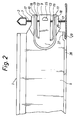
- Fig. 2 is a side view of the end portion of a transverse section connected to a main section which is shown in cross-section.
- Fig. 3 is a part-sectional view of the web part of the main section in the plane of the web part, illustrating the cooperation between the locking and guiding tongues of two transverse sections and the connecting hole of the main section according to Figs 1 and 2.
- Fig. 4 is a view of the same type as in Fig. 3, but illustrating an alternative embodiment of the connecting hole and the guiding tongues.
- Fig. 1 illustrates the connecting of two oppositely arranged transverse sections 1, 2 to a main section 3.
- the sections of which only small portions are shown, can be included in a suspended ceiling suspension system of conventional type and are as usual of an inverted T-form having a web part and, at the bottom thereof, side flanges projecting in the respective directions.
- the sections are made of metal and can be roll-formed.
- Figs 2 and 3 The connecting of the transverse sections to the main section is illustrated in more detail in Figs 2 and 3, Fig. 2 showing, for the purpose of elucidation, only one transverse section.
- each transverse section From the web part end of each transverse section projects an integrated tongue-shaped extension 4, which is adapted to be inserted into and cooperate with a connecting hole 6 in the web part 7 of the main section 3.
- the extension 4 like a connecting portion of the web part 5 of the transverse section, is pressed out or laterally offset, thereby obtaining a correct centring of the two transverse sections 1, 2 when the extensions 4 are inserted side by side into the connecting hole 6.
- Each extension 4 comprises a central locking tongue 9 and two separate guiding tongues 10, 11 arranged in parallel on both sides of the locking tongue 9.
- the guiding tongues 10, 11 are separated from the locking tongue 9 by slots 12, 13 being formed from the free end of the extension 4 and in parallel inwards in the longitudinal direction of the transverse section 1, such that the slots 12, 13 extend into the web part 5 of the transverse section 1.
- the slots 12, 13 extend a distance of different length into the web part. In the embodiment illustrated, the lower slot 13 extends inwards a longer distance than the upper slot 12.
- the planar locking tongue 9 is at its end fitted with a hook member in the form of a punched tongue member 15, which has an abutment surface facing the transverse section and adapted to cooperate with the "rear side" of the web part 7 of the main section 3.
- the hook member 15 is indicated by dashed lines in Figs 3 and 4.
- each guiding tongue 10, 11 are angular in cross-section (see Figs 3 and 4) for adaptation to the guide hole portions of the connecting hole 6 for the purpose of positioning each transverse section 1, 2 relative to the main section 3.
- each guiding tongue 10, 11 thus has an outer part 17 extending substantially in parallel with the web part 5, an intermediate inclined part 18, and an inner part 19 adjoining the pertaining slot and also extending substantially in parallel with the web part 5 but being further laterally offset away from the web part 5.
- the connecting hole 6 has a central portion with parallel walls, which is adapted to receive the locking tongues 9. This portion is of a width which is slightly greater than the sum of the thickness of the locking tongues 9 and the lateral extent of the hook member 15 from the locking tongue 9. As will be immediately appreciated, it will thus be possible to insert, for instance, a second locking tongue with its hook member 15 into the connecting hole 6, although a first locking tongue has ' already been inserted. To make it possible for the hook member 15 of each locking tongue to pass through the connecting hole 6 during mounting or dismounting, the locking tongue 9 must, as will be appreciated, be laterally bent, such that the hook member 15 will be aligned with the connecting hole 6 and can pass therethrough. Owing to the inventive configuration, such bending requires but little force because of the long spring excursion of the locking tongue 9 and the lack of reinforcements etc. of the locking tongue.
- the connecting hole 6 has special guide hole portions adapted to receive and position the guiding tongues 10, 11.
- the guide holes for the guiding tongues consist of the upper and lower, specially designed end portions 21, 22 of the connecting hole 6.
- the end portions are designed in such a manner that the guiding tongues 10, 11 while being inserted are automatically given a predetermined position.
- a very accurate positioning is achieved when the guiding tongues of two oppositely arranged transverse sections are inserted and cooperate with each other and with the walls of the connecting hole.
- the inner part 19 of the guiding tongues 9, 10 engages with the side walls of the guide hole portions 21, 22, while the outer parts 17 of the guiding tongues abut against each other and simultaneously fill the ends of the hole portions 21, 22 to a considerable extent, the dimensions of said ends being reduced.
- the height of the connecting hole 6 corresponds to the width of the tongue extension 4, i.e. the outer edges of the guiding tongue parts 17 connect with the top and bottom 23, 24, respectively, of the connecting hole 6, which results in improved stability and positioning.
- the walls of the hole portions 21, 22 could be further adapted in respect of form to the profile of the guiding tongues 9, 10 for the purpose of also improving the positioning.
- the lower guiding tongue 11 is, in the embodiment shown in Figs 1-3, provided with a stepped abutment surface 25 on the outer part 17, said abutment surface 25 being adapted to abut against the web part of the main section immediately below the connecting hole 6.
- a corresponding abutment surface could, of course, be arranged alternatively or also on the upper guiding tongue 10.
- each transverse section has a stepped terminal area 27 ending the lower flange part 28.
- This area is adapted to rest on the border area 29 of the lower side flange of the main section 3, such that a planar lower surface is obtained and the positioning is further improved.
- the edge of the border area 29 suitably abuts against the stepped surface which forms in the position where the terminal area 27 begins.
- Fig. 4 illustrates a further embodiment of the invention, which means that a transverse section is exactly positioned quite independently of whether there is an oppositely arranged transverse section or not. This is achieved by each guiding tongue 30, 31 being individually locked in a form-fit manner in a pertaining guide hole, which here, too, consists of end portions of the connecting hole 6.
- the guiding tongues 30, 31 are angled once and have an inner part 33 essentially corresponding to the part 19 in Fig. 3, and, connected therewith, an outwardly angled outer part 34.
- the part 33 cooperates with the associated vertical hole side wall, while the part 34 largely fills a corresponding, outwardly angled corner hole extension 35.
- an arrangement is thus provided, which permits extremely simple and reliable mounting and dismounting of transverse sections.
- Such outwards bending can be effected by gently pressing the locking tongue with a finger or a thumb, and this can be carried out on any side of the main section. This possibility is particularly advantageous, since in many cases the accessibility is not the same on both sides of the main section.
Landscapes
- Engineering & Computer Science (AREA)
- General Engineering & Computer Science (AREA)
- Architecture (AREA)
- Mechanical Engineering (AREA)
- Physics & Mathematics (AREA)
- Electromagnetism (AREA)
- Civil Engineering (AREA)
- Structural Engineering (AREA)
- Connection Of Plates (AREA)
- Residential Or Office Buildings (AREA)
- Mutual Connection Of Rods And Tubes (AREA)
- Paper (AREA)
- Electrical Discharge Machining, Electrochemical Machining, And Combined Machining (AREA)
- Mechanical Coupling Of Light Guides (AREA)
- Joining Of Building Structures In Genera (AREA)
- Clamps And Clips (AREA)
Claims (12)
- Agencement destiné à l'assemblage d'au moins une section transversale (1, 2) et d'une section principale (3) dans un système constitué de sections, en particulier destiné à supporter des plafonds suspendus, ledit agencement comprenant une languette de verrouillage saillante (9) disposée sur l'extrémité de la section transversale et comportant un élément de crochet saillant latéralement (15) et, formé dans la section principale, un trou d'assemblage (6) destiné à recevoir ladite languette de verrouillage, la languette de verrouillage étant agencée pour être élastique latéralement durant l'opération d'assemblage lorsqu'elle est insérée dans le trou d'assemblage et durant l'opération de désassemblage lorsqu'elle est extraite du trou d'assemblage, afin de permettre ainsi que l'élément de crochet (15) passe au travers du trou d'assemblage (6) pour venir en prise de verrouillage sur le côté opposé de la section principale (3), et revienne de cette prise de verrouillage en retour au travers du trou d'assemblage, respectivement, des moyens de guidage (10, 11) étant agencés sur l'extrémité de la section transversale (1, 2) en vue de coopérer avec la section principale (3), afin de communiquer ainsi à la section transversale et à la section principale une position relative fixe lorsqu'elles sont assemblées, caractérisé en ce quelesdits moyens de guidage (10, 11) sont séparés de la languette de verrouillage et indépendants etcomprennent une ou plusieurs languettes de guidage (10, 11) dépassant de l'extrémité de la section transversale (1, 2) et agencées pour s'engager dans des trous de guidage correspondants (21, 22 ; 35) dans la section principale en position assemblée.
- Agencement selon la revendication 1, caractérisé en ce que lesdits moyens de guidage séparés comprennent des languettes de guidage (10, 11) agencées au-dessus de la languette de verrouillage (9) et en-dessous de la languette de verrouillage (9), respectivement.
- Agencement selon la revendication 1 ou 2,
caractérisé en ce que chaque trou de guidage (21, 22 ; 35) est constitué d'une partie du trou d'assemblage (6) de la languette de verrouillage (9). - Agencement selon la revendication 3, caractérisé en ce que lesdits trous de guidage sont constitués de parties d'extrémité opposées (21, 22) du trou d'assemblage (6), la partie intermédiaire du trou d'assemblage étant conçue pour recevoir la languette de verrouillage (9) entre deux languettes de guidage (10, 11).
- Agencement selon l'une quelconque des revendications précédentes, caractérisé en ce que la languette de verrouillage (9) dépasse librement de la section transversale (1, 2) à partir d'une position sur celle-ci, qui après raccordement est sensiblement espacée de la partie d'âme (7) de la section principale (3), de préférence adjacente ou à l'extérieur du bord extérieur longitudinal (29) du rebord latéral inférieur de la section principale, de sorte que la languette de verrouillage durant l'assemblage et le désassemblage, respectivement, peut être élastique latéralement en commençant à une distance notable de la partie d'âme de la section principale.
- Agencement selon l'une quelconque des revendications précédentes, caractérisé en ce que la languette de verrouillage (9) est munie dudit élément de crochet (15) immédiatement à proximité de son extrémité libre.
- Agencement selon l'une quelconque des revendications précédentes, caractérisé en ce qu'une languette de verrouillage centrale (9) de même que des moyens de guidage sous forme de languettes de guidage (10, 11) agencées des deux côtés de la languette de verrouillage sont formées en un prolongement en forme de languette (4) de la partie d'âme (5) de la section transversale, la languette de verrouillage et les languettes de guidage étant séparées par une fente (12, 13) sur chaque côté de la languette de verrouillage (9), lesdites fentes s'étendant depuis l'extrémité libre du prolongement en forme de languette (4) et longitudinalement en direction de la partie d'âme (5) de la section transversale.
- Agencement selon la revendication 7,
caractérisé en ce qu'au moins l'une (13) des fentes (12, 13) s'étend jusque dans la partie d'âme (5) de la section transversale (1, 2). - Agencement selon la revendication 7 ou 8, caractérisé en ce que les fentes (12, 13) s'étendent sur une distance de longueur différente en direction de la partie d'âme (5) de la section transversale (1, 2) ou jusque dans celle-ci.
- Agencement selon l'une quelconque des revendications précédentes, caractérisé en ce que lesdits moyens de guidage comprennent une zone terminale étagée (27) ou projection sur la partie de semelle inférieure (28) de la section transversale (1, 2), ladite zone terminale ou projection étant conçue pour reposer sur la zone de bordure (29) de la semelle latérale inférieure de la section principale (3).
- Agencement selon l'une quelconque des revendications précédentes, destiné à assembler une section principale (3) et deux sections transversales (1, 2) alignées l'une avec l'autre et agencées sur des côtés opposés de la section principale, les languettes de verrouillage (9) des sections transversales étant conçues pour être insérées en parallèle dans le trou d'assemblage (6), caractérisé en ce que les languettes de guidage des deux sections transversales (1, 2) sont conçues pour coopérer afin d'obtenir la position fixe lors de la réalisation de l'assemblage.
- Agencement selon l'une quelconque des revendications précédentes, destiné à assembler une section principale (3) et deux sections transversales (1, 2) alignées l'une avec l'autre et agencées sur les côtés opposés de la section principale, les languettes de verrouillage (9) des sections transversales étant conçues pour être insérées en parallèle dans le trou d'assemblage (6), caractérisé en ce que les languettes de guidage (30, 31) des deux sections transversales sont conçues pour obtenir, indépendamment l'une de l'autre, la position fixe de chaque section transversale.
Applications Claiming Priority (2)
| Application Number | Priority Date | Filing Date | Title |
|---|---|---|---|
| SE9501638A SE504079C2 (sv) | 1995-05-03 | 1995-05-03 | Anordning för hopkoppling av profiler |
| SE9501638 | 1995-05-03 |
Publications (3)
| Publication Number | Publication Date |
|---|---|
| EP0747548A2 EP0747548A2 (fr) | 1996-12-11 |
| EP0747548A3 EP0747548A3 (fr) | 1997-01-29 |
| EP0747548B1 true EP0747548B1 (fr) | 2000-07-05 |
Family
ID=20398179
Family Applications (1)
| Application Number | Title | Priority Date | Filing Date |
|---|---|---|---|
| EP96850084A Expired - Lifetime EP0747548B1 (fr) | 1995-05-03 | 1996-04-29 | Dispositif pour l'assemblage de sections |
Country Status (9)
| Country | Link |
|---|---|
| US (1) | US5893249A (fr) |
| EP (1) | EP0747548B1 (fr) |
| AT (1) | ATE194403T1 (fr) |
| AU (1) | AU5661496A (fr) |
| DE (1) | DE69609125T2 (fr) |
| DK (1) | DK0747548T3 (fr) |
| RU (1) | RU2160344C2 (fr) |
| SE (1) | SE504079C2 (fr) |
| WO (1) | WO1996035026A1 (fr) |
Families Citing this family (19)
| Publication number | Priority date | Publication date | Assignee | Title |
|---|---|---|---|---|
| US6138416A (en) * | 1998-11-12 | 2000-10-31 | Worthington Armstrong Venture | Beam |
| US6851238B2 (en) * | 2002-03-14 | 2005-02-08 | Robert J. Rebman | Ceiling grid system and method of assembling the same |
| CA2413621A1 (fr) * | 2002-12-05 | 2004-06-05 | William Cobb | Raccord mural a barre en t |
| US20070028554A1 (en) * | 2005-08-05 | 2007-02-08 | James Ferrell | High strength runner |
| US20070175152A1 (en) * | 2005-12-20 | 2007-08-02 | Kupec Thoms F | Single strip - double web ceiling grid member |
| US7516585B2 (en) * | 2005-11-21 | 2009-04-14 | Usg Interiors, Inc. | Grid tee for suspension ceiling |
| US20080155934A1 (en) * | 2006-12-29 | 2008-07-03 | Usg Interiors, Inc. | Easy cut suspension grid |
| US8117793B2 (en) * | 2007-12-28 | 2012-02-21 | Chicago Metallic Corporation | Suspended ceiling grid assembly with separation joints |
| GB2456328A (en) * | 2008-01-11 | 2009-07-15 | Usg Interiors Inc | Grid members for a suspended ceiling and methods of making same |
| USD668352S1 (en) | 2008-01-11 | 2012-10-02 | Usg Interiors, Llc | Suspended ceiling wall angle |
| US20100064618A1 (en) * | 2008-09-15 | 2010-03-18 | Certainteed Corporation | Ceiling tile and edge suspension system |
| US20110078970A1 (en) * | 2009-10-01 | 2011-04-07 | Certainteed Corporation | Ceiling tile and edge suspension system |
| RU2480564C1 (ru) * | 2011-10-31 | 2013-04-27 | Общество С Ограниченной Ответственностью "Производственная Фирма "Альта-Профиль" | Профиль облицовочный угловой |
| ITVE20110082A1 (it) * | 2011-12-19 | 2013-06-20 | Dallan Spa | Corrente a t rovescia per realizzare strutture di sostegno di controsoffittature |
| ITVR20130040A1 (it) * | 2013-02-14 | 2014-08-15 | Giuseppe Cipriani | Struttura metallica di supporto di un controsoffitto. |
| US9637918B1 (en) * | 2016-01-06 | 2017-05-02 | Usg Interiors, Llc | Cross runner to main runner anchor clip |
| DK3246482T3 (da) * | 2016-05-20 | 2022-04-25 | Saint Gobain Ecophon Ab | Tværskinneforbindelsesdel, bæreprofil og tværskinneforbindelsesdelsarrangement til et nedhængt loftsystem |
| GB2573811B (en) * | 2018-05-18 | 2020-12-30 | Trieste Group One Ltd | Modular Frame |
| EP3862501B1 (fr) * | 2020-02-04 | 2023-10-11 | Saint-Gobain Ecophon AB | Connecteur de profil secondaire pour un système de plafond suspendu |
Family Cites Families (17)
| Publication number | Priority date | Publication date | Assignee | Title |
|---|---|---|---|---|
| US2840200A (en) * | 1955-06-30 | 1958-06-24 | Cepco Inc | Structural connector |
| US3096862A (en) * | 1960-09-07 | 1963-07-09 | W J Haertel & Co | Ceiling suspension system with double locking clip |
| US3898782A (en) * | 1974-01-04 | 1975-08-12 | Lightolier Inc | Integrated ceiling system |
| US4264231A (en) * | 1980-03-04 | 1981-04-28 | Roper Corporation | Joint between main beam and cross beams in suspended ceiling system |
| US4364686A (en) * | 1980-11-17 | 1982-12-21 | Lok Products Company | Locking device for grid system |
| US4535580A (en) * | 1981-07-09 | 1985-08-20 | Donn Incorporated | Screw slot runner system |
| GB2145752B (en) * | 1983-08-27 | 1986-10-29 | Phoenix Rollformed Sections Li | Suspension ceiling grids |
| DE205673T1 (de) * | 1985-06-28 | 1987-05-21 | Chicago Metallic Continental N.V., Wijnegem | Verbindung fuer profile abgehaengter decken. |
| US4648230A (en) * | 1985-07-24 | 1987-03-10 | Donn Incorporated | Locking connection for suspension ceiling grid systems |
| GB2178087B (en) * | 1985-07-24 | 1989-02-15 | Donn Inc | Suspension ceiling system |
| US4611453A (en) * | 1985-07-25 | 1986-09-16 | Donn Incorporated | Suspension ceiling grid connectors |
| US4621474A (en) * | 1985-07-25 | 1986-11-11 | Donn Incorporated | Grid connectors for suspension ceiling |
| US4712350A (en) * | 1986-05-16 | 1987-12-15 | Chicago Metallic Corporation | Centering arrangement for T members of a suspended ceiling |
| US4827681A (en) * | 1986-11-28 | 1989-05-09 | National Rolling Mills, Inc. | Interlocking cross tee |
| DE3939632A1 (de) * | 1989-11-30 | 1991-06-06 | Karl Dr Goltz | Zerlegbarer, stufenartiger tisch, deren platten drehbar sind |
| DE3939692A1 (de) * | 1989-12-01 | 1991-06-06 | Richter System Gmbh & Co Kg | Traggitter fuer unterdecke |
| US5154031A (en) * | 1991-03-26 | 1992-10-13 | Schilling Components, Incorporated | Suspended ceiling system and connector clip therefor |
-
1995
- 1995-05-03 SE SE9501638A patent/SE504079C2/sv not_active IP Right Cessation
-
1996
- 1996-04-29 US US08/945,559 patent/US5893249A/en not_active Expired - Fee Related
- 1996-04-29 RU RU97119876/03A patent/RU2160344C2/ru active
- 1996-04-29 DK DK96850084T patent/DK0747548T3/da active
- 1996-04-29 AU AU56614/96A patent/AU5661496A/en not_active Abandoned
- 1996-04-29 EP EP96850084A patent/EP0747548B1/fr not_active Expired - Lifetime
- 1996-04-29 WO PCT/SE1996/000560 patent/WO1996035026A1/fr active Application Filing
- 1996-04-29 AT AT96850084T patent/ATE194403T1/de not_active IP Right Cessation
- 1996-04-29 DE DE69609125T patent/DE69609125T2/de not_active Expired - Lifetime
Also Published As
| Publication number | Publication date |
|---|---|
| WO1996035026A1 (fr) | 1996-11-07 |
| DE69609125T2 (de) | 2001-03-22 |
| US5893249A (en) | 1999-04-13 |
| AU5661496A (en) | 1996-11-21 |
| SE9501638D0 (sv) | 1995-05-03 |
| SE9501638L (sv) | 1996-11-04 |
| RU2160344C2 (ru) | 2000-12-10 |
| EP0747548A3 (fr) | 1997-01-29 |
| DK0747548T3 (da) | 2000-11-06 |
| SE504079C2 (sv) | 1996-11-04 |
| EP0747548A2 (fr) | 1996-12-11 |
| ATE194403T1 (de) | 2000-07-15 |
| DE69609125D1 (de) | 2000-08-10 |
Similar Documents
| Publication | Publication Date | Title |
|---|---|---|
| EP0747548B1 (fr) | Dispositif pour l'assemblage de sections | |
| US6520353B2 (en) | Shelf & bracket having snap-together fit | |
| US6286265B1 (en) | Recessed lighting fixture mounting | |
| US7975448B2 (en) | Drywall channel with pre-punched locating tabs | |
| US5785401A (en) | Vertical support for a slide mechanism in a cabinet | |
| CA1305209C (fr) | Tiroir | |
| US5253835A (en) | Shelf bracket assembly | |
| US4161856A (en) | Suspension ceiling system | |
| CA2640612A1 (fr) | Etrier a enclenchement | |
| US5271202A (en) | Suspended ceiling system with staked-on connectors | |
| US11717085B2 (en) | Suspension system for storage components | |
| EP0634580B1 (fr) | Ensemble de plaques et procédé d'assemblage | |
| NL195087C (nl) | Werkwijze en systeem voor het samenstellen van een wand. | |
| US5890784A (en) | Drawer slide | |
| EP1898016B1 (fr) | Faux plafond avec des panneaux pivotables par dessous | |
| JPH0531015A (ja) | 引出し | |
| US5597259A (en) | Plate assembly | |
| AU637479B2 (en) | A connecting device | |
| US5238115A (en) | Stackable transportation container of sheet metal | |
| US4129057A (en) | Keyboard support mechanism for electronic organs | |
| UA82342C2 (uk) | Вдосконалений з'єднувальний елемент для перевернутих таврових балок | |
| US4079563A (en) | Ceiling runner locking means | |
| GB2052594A (en) | Metal panelled ceiling | |
| NO167447B (no) | Grunnplate for en ordneinnretning for hullede ark. | |
| CN114599844B (zh) | 夹紧件、顶棚基底及其施工方法 |
Legal Events
| Date | Code | Title | Description |
|---|---|---|---|
| PUAI | Public reference made under article 153(3) epc to a published international application that has entered the european phase |
Free format text: ORIGINAL CODE: 0009012 |
|
| AK | Designated contracting states |
Kind code of ref document: A2 Designated state(s): AT BE CH DE DK ES FI FR GB GR IE IT LI LU MC NL PT SE |
|
| AX | Request for extension of the european patent |
Free format text: AL PAYMENT 960522;LT PAYMENT 960522;LV PAYMENT 960522;SI PAYMENT 960522 |
|
| PUAL | Search report despatched |
Free format text: ORIGINAL CODE: 0009013 |
|
| AK | Designated contracting states |
Kind code of ref document: A3 Designated state(s): AT BE CH DE DK ES FI FR GB GR IE IT LI LU MC NL PT SE |
|
| AX | Request for extension of the european patent |
Free format text: AL PAYMENT 960522;LT PAYMENT 960522;LV PAYMENT 960522;SI PAYMENT 960522 |
|
| 17P | Request for examination filed |
Effective date: 19970318 |
|
| 17Q | First examination report despatched |
Effective date: 19990208 |
|
| GRAG | Despatch of communication of intention to grant |
Free format text: ORIGINAL CODE: EPIDOS AGRA |
|
| GRAG | Despatch of communication of intention to grant |
Free format text: ORIGINAL CODE: EPIDOS AGRA |
|
| GRAH | Despatch of communication of intention to grant a patent |
Free format text: ORIGINAL CODE: EPIDOS IGRA |
|
| GRAH | Despatch of communication of intention to grant a patent |
Free format text: ORIGINAL CODE: EPIDOS IGRA |
|
| GRAA | (expected) grant |
Free format text: ORIGINAL CODE: 0009210 |
|
| AK | Designated contracting states |
Kind code of ref document: B1 Designated state(s): AT BE CH DE DK ES FI FR GB GR IE IT LI LU MC NL PT SE |
|
| AX | Request for extension of the european patent |
Free format text: AL PAYMENT 19960522;LT PAYMENT 19960522;LV PAYMENT 19960522;SI PAYMENT 19960522 |
|
| LTIE | Lt: invalidation of european patent or patent extension | ||
| PG25 | Lapsed in a contracting state [announced via postgrant information from national office to epo] |
Ref country code: LI Free format text: LAPSE BECAUSE OF FAILURE TO SUBMIT A TRANSLATION OF THE DESCRIPTION OR TO PAY THE FEE WITHIN THE PRESCRIBED TIME-LIMIT Effective date: 20000705 Ref country code: IT Free format text: LAPSE BECAUSE OF FAILURE TO SUBMIT A TRANSLATION OF THE DESCRIPTION OR TO PAY THE FEE WITHIN THE PRE;WARNING: LAPSES OF ITALIAN PATENTS WITH EFFECTIVE DATE BEFORE 2007 MAY HAVE OCCURRED AT ANY TIME BEFORE 2007. THE CORRECT EFFECTIVE DATE MAY BE DIFFERENT FROM THE ONE RECORDED.SCRIBED TIME-LIMIT Effective date: 20000705 Ref country code: FI Free format text: LAPSE BECAUSE OF FAILURE TO SUBMIT A TRANSLATION OF THE DESCRIPTION OR TO PAY THE FEE WITHIN THE PRESCRIBED TIME-LIMIT Effective date: 20000705 Ref country code: ES Free format text: THE PATENT HAS BEEN ANNULLED BY A DECISION OF A NATIONAL AUTHORITY Effective date: 20000705 Ref country code: CH Free format text: LAPSE BECAUSE OF FAILURE TO SUBMIT A TRANSLATION OF THE DESCRIPTION OR TO PAY THE FEE WITHIN THE PRESCRIBED TIME-LIMIT Effective date: 20000705 Ref country code: AT Free format text: LAPSE BECAUSE OF FAILURE TO SUBMIT A TRANSLATION OF THE DESCRIPTION OR TO PAY THE FEE WITHIN THE PRESCRIBED TIME-LIMIT Effective date: 20000705 |
|
| REF | Corresponds to: |
Ref document number: 194403 Country of ref document: AT Date of ref document: 20000715 Kind code of ref document: T |
|
| REG | Reference to a national code |
Ref country code: CH Ref legal event code: EP |
|
| REG | Reference to a national code |
Ref country code: IE Ref legal event code: FG4D |
|
| REF | Corresponds to: |
Ref document number: 69609125 Country of ref document: DE Date of ref document: 20000810 |
|
| ET | Fr: translation filed | ||
| PG25 | Lapsed in a contracting state [announced via postgrant information from national office to epo] |
Ref country code: PT Free format text: LAPSE BECAUSE OF FAILURE TO SUBMIT A TRANSLATION OF THE DESCRIPTION OR TO PAY THE FEE WITHIN THE PRESCRIBED TIME-LIMIT Effective date: 20001006 Ref country code: GR Free format text: LAPSE BECAUSE OF FAILURE TO SUBMIT A TRANSLATION OF THE DESCRIPTION OR TO PAY THE FEE WITHIN THE PRESCRIBED TIME-LIMIT Effective date: 20001006 |
|
| REG | Reference to a national code |
Ref country code: DK Ref legal event code: T3 |
|
| REG | Reference to a national code |
Ref country code: CH Ref legal event code: PL |
|
| PG25 | Lapsed in a contracting state [announced via postgrant information from national office to epo] |
Ref country code: LU Free format text: LAPSE BECAUSE OF NON-PAYMENT OF DUE FEES Effective date: 20010429 |
|
| PG25 | Lapsed in a contracting state [announced via postgrant information from national office to epo] |
Ref country code: MC Free format text: LAPSE BECAUSE OF NON-PAYMENT OF DUE FEES Effective date: 20010430 Ref country code: IE Free format text: LAPSE BECAUSE OF NON-PAYMENT OF DUE FEES Effective date: 20010430 |
|
| PLBE | No opposition filed within time limit |
Free format text: ORIGINAL CODE: 0009261 |
|
| STAA | Information on the status of an ep patent application or granted ep patent |
Free format text: STATUS: NO OPPOSITION FILED WITHIN TIME LIMIT |
|
| 26N | No opposition filed | ||
| REG | Reference to a national code |
Ref country code: GB Ref legal event code: IF02 |
|
| REG | Reference to a national code |
Ref country code: IE Ref legal event code: MM4A |
|
| PGFP | Annual fee paid to national office [announced via postgrant information from national office to epo] |
Ref country code: DK Payment date: 20090407 Year of fee payment: 14 |
|
| PGFP | Annual fee paid to national office [announced via postgrant information from national office to epo] |
Ref country code: NL Payment date: 20090406 Year of fee payment: 14 Ref country code: FR Payment date: 20090403 Year of fee payment: 14 |
|
| PGFP | Annual fee paid to national office [announced via postgrant information from national office to epo] |
Ref country code: BE Payment date: 20090406 Year of fee payment: 14 |
|
| BERE | Be: lapsed |
Owner name: *ECOPHON A.B. Effective date: 20100430 |
|
| REG | Reference to a national code |
Ref country code: NL Ref legal event code: V1 Effective date: 20101101 |
|
| REG | Reference to a national code |
Ref country code: DK Ref legal event code: EBP |
|
| REG | Reference to a national code |
Ref country code: FR Ref legal event code: ST Effective date: 20101230 |
|
| PG25 | Lapsed in a contracting state [announced via postgrant information from national office to epo] |
Ref country code: NL Free format text: LAPSE BECAUSE OF NON-PAYMENT OF DUE FEES Effective date: 20101101 |
|
| PG25 | Lapsed in a contracting state [announced via postgrant information from national office to epo] |
Ref country code: BE Free format text: LAPSE BECAUSE OF NON-PAYMENT OF DUE FEES Effective date: 20100430 |
|
| PG25 | Lapsed in a contracting state [announced via postgrant information from national office to epo] |
Ref country code: DK Free format text: LAPSE BECAUSE OF NON-PAYMENT OF DUE FEES Effective date: 20100503 |
|
| PG25 | Lapsed in a contracting state [announced via postgrant information from national office to epo] |
Ref country code: FR Free format text: LAPSE BECAUSE OF NON-PAYMENT OF DUE FEES Effective date: 20100430 |
|
| PGFP | Annual fee paid to national office [announced via postgrant information from national office to epo] |
Ref country code: DE Payment date: 20120405 Year of fee payment: 17 |
|
| PGFP | Annual fee paid to national office [announced via postgrant information from national office to epo] |
Ref country code: GB Payment date: 20120410 Year of fee payment: 17 Ref country code: SE Payment date: 20120416 Year of fee payment: 17 |
|
| REG | Reference to a national code |
Ref country code: SE Ref legal event code: EUG |
|
| GBPC | Gb: european patent ceased through non-payment of renewal fee |
Effective date: 20130429 |
|
| PG25 | Lapsed in a contracting state [announced via postgrant information from national office to epo] |
Ref country code: SE Free format text: LAPSE BECAUSE OF NON-PAYMENT OF DUE FEES Effective date: 20130430 Ref country code: GB Free format text: LAPSE BECAUSE OF NON-PAYMENT OF DUE FEES Effective date: 20130429 Ref country code: DE Free format text: LAPSE BECAUSE OF NON-PAYMENT OF DUE FEES Effective date: 20131101 |
|
| REG | Reference to a national code |
Ref country code: DE Ref legal event code: R119 Ref document number: 69609125 Country of ref document: DE Effective date: 20131101 |