EP0747125B1 - Verfahren und Vorrichtung zur Herstellung von einmalig verwendbaren Pipettenspitzen in einem Analysengerät - Google Patents
Verfahren und Vorrichtung zur Herstellung von einmalig verwendbaren Pipettenspitzen in einem Analysengerät Download PDFInfo
- Publication number
- EP0747125B1 EP0747125B1 EP96304127A EP96304127A EP0747125B1 EP 0747125 B1 EP0747125 B1 EP 0747125B1 EP 96304127 A EP96304127 A EP 96304127A EP 96304127 A EP96304127 A EP 96304127A EP 0747125 B1 EP0747125 B1 EP 0747125B1
- Authority
- EP
- European Patent Office
- Prior art keywords
- port
- tip
- pipette
- probe
- dispensing
- Prior art date
- Legal status (The legal status is an assumption and is not a legal conclusion. Google has not performed a legal analysis and makes no representation as to the accuracy of the status listed.)
- Expired - Lifetime
Links
- 238000000034 method Methods 0.000 title claims abstract description 9
- 239000000523 sample Substances 0.000 claims abstract description 58
- 239000007788 liquid Substances 0.000 claims description 21
- 230000007246 mechanism Effects 0.000 claims description 8
- 238000004519 manufacturing process Methods 0.000 claims description 7
- 230000033001 locomotion Effects 0.000 abstract description 2
- 238000011065 in-situ storage Methods 0.000 abstract 1
- 238000003780 insertion Methods 0.000 abstract 1
- 230000037431 insertion Effects 0.000 abstract 1
- 238000012360 testing method Methods 0.000 description 6
- 229920003023 plastic Polymers 0.000 description 4
- 239000004033 plastic Substances 0.000 description 4
- 239000008280 blood Substances 0.000 description 1
- 210000004369 blood Anatomy 0.000 description 1
- 239000006229 carbon black Substances 0.000 description 1
- 238000012864 cross contamination Methods 0.000 description 1
- 238000005520 cutting process Methods 0.000 description 1
- 230000001934 delay Effects 0.000 description 1
- 230000026058 directional locomotion Effects 0.000 description 1
- 230000000977 initiatory effect Effects 0.000 description 1
- 239000000463 material Substances 0.000 description 1
- 230000004048 modification Effects 0.000 description 1
- 238000012986 modification Methods 0.000 description 1
- 239000002245 particle Substances 0.000 description 1
- 239000013610 patient sample Substances 0.000 description 1
- 229920000642 polymer Polymers 0.000 description 1
- 238000012207 quantitative assay Methods 0.000 description 1
Images




Classifications
-
- G—PHYSICS
- G01—MEASURING; TESTING
- G01N—INVESTIGATING OR ANALYSING MATERIALS BY DETERMINING THEIR CHEMICAL OR PHYSICAL PROPERTIES
- G01N35/00—Automatic analysis not limited to methods or materials provided for in any single one of groups G01N1/00 - G01N33/00; Handling materials therefor
- G01N35/10—Devices for transferring samples or any liquids to, in, or from, the analysis apparatus, e.g. suction devices, injection devices
- G01N35/1009—Characterised by arrangements for controlling the aspiration or dispense of liquids
-
- B—PERFORMING OPERATIONS; TRANSPORTING
- B01—PHYSICAL OR CHEMICAL PROCESSES OR APPARATUS IN GENERAL
- B01L—CHEMICAL OR PHYSICAL LABORATORY APPARATUS FOR GENERAL USE
- B01L3/00—Containers or dishes for laboratory use, e.g. laboratory glassware; Droppers
- B01L3/02—Burettes; Pipettes
- B01L3/0275—Interchangeable or disposable dispensing tips
-
- G—PHYSICS
- G01—MEASURING; TESTING
- G01N—INVESTIGATING OR ANALYSING MATERIALS BY DETERMINING THEIR CHEMICAL OR PHYSICAL PROPERTIES
- G01N35/00—Automatic analysis not limited to methods or materials provided for in any single one of groups G01N1/00 - G01N33/00; Handling materials therefor
- G01N35/10—Devices for transferring samples or any liquids to, in, or from, the analysis apparatus, e.g. suction devices, injection devices
- G01N35/1009—Characterised by arrangements for controlling the aspiration or dispense of liquids
- G01N2035/1025—Fluid level sensing
-
- G—PHYSICS
- G01—MEASURING; TESTING
- G01N—INVESTIGATING OR ANALYSING MATERIALS BY DETERMINING THEIR CHEMICAL OR PHYSICAL PROPERTIES
- G01N35/00—Automatic analysis not limited to methods or materials provided for in any single one of groups G01N1/00 - G01N33/00; Handling materials therefor
- G01N35/10—Devices for transferring samples or any liquids to, in, or from, the analysis apparatus, e.g. suction devices, injection devices
- G01N2035/1027—General features of the devices
- G01N2035/103—General features of the devices using disposable tips
Definitions
- This invention is directed to a method and apparatus for making disposable tips for a dispensing probe of an analyzer, preferably within and as part of the analyzer.
- a method of making a pipette tip for mounting inside a port of a pipette or dispensing probe comprises the steps of claim 1.
- the problems are solved by apparatus for forming a pipette tip inserted into a port of a pipette or a dispensing probe, the apparatus comprising first and second die plates having first surfaces facing and in sliding contact with each other, and first and second apertures respectively therein, generally aligned with each other to form an axis, the first of the plates having a third aperture generally coaxial with the first aperture of the first plate, for receiving a port of the pipette or dispersing probe therein, means for sliding the plates relative to each other along the first surfaces in a direction generally transverse to the axis, and engaging means for frictionally engaging and pushing a continuous cylindrical stock through the plates to create a pipette tip.
- a dispensing station in an analyzer for assaying analytes in a biological liquid comprising:
- a disposable tip can be manufactured out of a simple cylindrical tube without sacrificing dispensing accuracy.
- the invention is described hereinafter in connection with preferred embodiments, wherein preferred dies are used to sever individual tips from continuous stock of cylindrical shape, fed by counter-rotating rollers, to dispense sample liquid.
- the invention is useful regardless of the severing mechanism used, or the shape of the continuous stock, or whether the advancing means used are rollers or some other device. Additionally, it is useful regardless of the type of liquid being aspirated and dispensed, and regardless of the type of test material receiving the liquid.
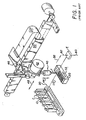
- Fig. 1 shows particular prior art, for example, the analyzer of US-A-5,008,082.
- patient sample liquid is supplied by containers C (shown as tubes) carried by a carrier 10 which is shown to be linear and linearly driven by a belt 20.
- carrier 10 can be a rotor that is rotated.
- Disposable tips T are provided pre-made, for example, as the "rocket" type of US-A-4,347,875, and are supplied on a tray 30 that advances linearly, arrow 32, but which can alternatively also be a rotor.
- a dispensing probe 40 is connected to a pump 42 for creating aspirating vacuum and dispensing pressure, as is well-known. Probe 40 in turn is mounted for vertical reciprocation, arrow 44, on a carrier 46 that traverses linearly, arrow 48, along a track 50.
- the purpose is to cause probe to move first to tray 30 to pick up a tip T, then to carrier 10 to aspirate a liquid sample into the tip from a container C, and then back, arrow 52, to a new station 60 which is the dispense station where tip T is lowered, arrow 62, to allow liquid sample to be dispensed onto a dried slide test element E, such as those available heretofore from Clinical Diagnostic Systems, Inc., a Johnson & Johnson company, under the trademark "Ektachem”.
- a dried slide test element E such as those available heretofore from Clinical Diagnostic Systems, Inc., a Johnson & Johnson company, under the trademark "Ektachem”.
- tray 30 requires manual loading of the tips, by an operator or operator assistant, and hence pre-manufacture of the tips, and in a special mold.
- Fig. 2 tray 30 and the pre-manufacture of the tips are replaced by a mechanism 100, Fig. 2, which is part of the automated analyzer.
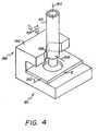
- This mechanism comprises first and second opposing die plates 102, 104 each having a sliding contact surface 106 that contacts the other plate, and a surface 108, 110, respectively, opposite to surface 106.
- Each surface 106 in turn is apertured at 112, 114, respectively, with preferably a cylindrical shape of substantially matching diameters D1.
- Opposing surface 110 is either the exit location of aperture 114, or optionally it can be chamfered, as shown at 120.
- Opposing surface 108 is preferably provided with yet another aperture 122 that is cylindrical and coaxially aligned with aperture 112, albeit with a diameter larger than D1. Because its function is to receive the port end of a dispensing probe (shown hereinafter), it optionally can also be chamfered at 124.
- arrows 130 either or both of the plates is connected to a driver 132,134 respectively.
- drivers comprise any conventional mechanism, such as a rack-and-pinion drive using a stepper motor, a hydraulic piston drive, or a belt drive.
- Constraining rollers or equivalent mechanisms 140 such as tracks, are used to keep plates 102 and 104 from moving out of their position planes shown in Fig. 2.
- the actual disposable tip is formed from a continuous stock of a hollow tube T having preferably a substantially cylindrical cross-sectional shape of constant diameter, selected from any suitable plastic, for example, those used conventionally for tip manufacture.
- This tube is supplied from an "endless” supply, such as large roll 150 (having side flanges on both sides to confine the roll, only flange 152 being shown.)
- rollers 160,162 To engage and advance tube stock T, means such as opposite and counter-rotating rollers 160,162 are provided, having a nip 164 spaced to frictionally engage tube T. Nip 164 is coaxially aligned with aperture 114 at least during the tube stock-advancing stage. Rollers 160,162 are driven by any suitable, conventional mechanism.
- Alternative tube-advancing means include oscillating jaws, not shown, that clamp on the tube, advance it into the die plates, unclamp, and return to the first position for clamping.
- the dispensing probe 40 is also preferably further modified, Fig. 3, to include a hollow ejector cylinder 170, mounted inside port 171 of probe 40, because the preferred embodiment provides for the tip to be engaged inside the probe, rather than outside.
- a hollow ejector cylinder 170 mounted inside port 171 of probe 40, because the preferred embodiment provides for the tip to be engaged inside the probe, rather than outside.
- the tip formed from tube T as described hereinafter, is inserted over and around the outside of the probe, as is the case with tips T of the aforesaid '082 patent, then the ejector can be mounted on the outside of probe 40.
- Probe 40 is further preferably modified to include a chamfered surface 172 of gradually reduced or tapered diameter, spaced away from extreme end 174 of the probe. This leaves a hollow bore 175, of slightly larger diameter than that of 172.
- the taper of surface 172 is such as to squeeze onto the extreme end 199 of tube stock T as it is fed into the probe, thus positively engaging what becomes the "tip".
- a sideways support 190 comprising a plate 192 having a v-shaped notch 193 with a vertical axis 194, to receive a formed tip and to stabilize it during dispensing, as discussed below.
- Probe 40 is inserted into aperture 122, Fig. 3, and seated on a shoulder 196 that is the junction between aperture 112 and aperture 122.
- plates 102 and 104 are slidably adjusted so that apertures 114 and 112 are aligned coaxially along a stock-passage axis 198, Fig. 2.
- Fig. 3 the extreme end 199 of tube T is moved into, first, aperture 114 by pushing it through the rotation of rollers 160, 162, arrows 200.
- the rollers continue to push tube T in direction A through aperture 112, Fig. 5, into port 171 until end 199 of tube T seats frictionally within chamfer 172.
- the two plates are slid sideways relative to each other in a direction 202 generally traverse to axis 198, in this case by moving just plate 104.
- This severs tube T i at the contacting faces 106 of the die plates.
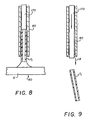
- Probe 40 is then withdrawn from aperture 122, Fig. 7, along with tip T i , and is moved to a sample container, such as a container C, Fig. 1, where tip T i only, is inserted into the liquid to aspirate it. Then probe 40, tip T i , and its liquid are moved to a dispensing station, such as station 60, Fig.
- ejector 170 advances through probe 40, Fig. 9, to force tip T i out of its engagement within probe 40, in direction B opposite to direction A, Fig. 5.
- Probe 40 is then returned to its position wherein it is inserted into and seated within aperture 122, so that it can receive once again, tube T along direction A, Fig. 5, with a new extreme end for engagement within chamfered surface 172.
- the tube cutting process, and tip usage, is repeated to create a new disposable tip T i+1 (not shown) for use with the next sample liquid.
- the process is used repeatedly, to create up to T i+n new tips.
- tube T can be selected from conductive plastics, instead of non-conductive plastics. That is, it can comprise a polymer having sufficient carbon black particles as to render tip T i , T i+1 and T i+n electrically conductive.
- probe 40 can sense the liquid level in containers C, using tip T i , T i+1 or T i+n and a capacitance sensing circuit to detect when the tip contacts the liquid, as is well-known. See, for example, US-A-4,326,851.
Landscapes
- Chemical & Material Sciences (AREA)
- Health & Medical Sciences (AREA)
- Immunology (AREA)
- Pathology (AREA)
- Analytical Chemistry (AREA)
- Biochemistry (AREA)
- General Health & Medical Sciences (AREA)
- General Physics & Mathematics (AREA)
- Physics & Mathematics (AREA)
- Life Sciences & Earth Sciences (AREA)
- Clinical Laboratory Science (AREA)
- Chemical Kinetics & Catalysis (AREA)
- Sampling And Sample Adjustment (AREA)
- Automatic Analysis And Handling Materials Therefor (AREA)
- Devices For Use In Laboratory Experiments (AREA)
- Other Investigation Or Analysis Of Materials By Electrical Means (AREA)
Claims (10)
- Verfahren zum Herstellen einer Pipettenspitze (Ti) zum Anbringen in einer Öffnung (171) einer Pipette oder einer Abgabesonde (40), gekennzeichnet durcha) Schieben eines zylindrischen Materials (T) von kontinuierlicher Länge durch eine erste und eine zweite Stempelplatte (102, 104), die erste Oberflächen (106) aufweisen, die einander gegenüberliegen und miteinander in Gleitkontakt stehen, und einer ersten und einer zweiten Öffnung (112, 114) in diesen, die im wesentlichen miteinander ausgerichtet sind, um eine Achse (198) zu bilden, durch die das zylindrische Material (T) verläuft, wobei die erste der Platten (102) eine dritte Öffnung (122) aufweist, die im wesentlichen koaxial mit der ersten Öffnung der ersten Platte (102) ist und ausgeht von einer Oberfläche der ersten Platte (102), die der ersten Oberfläche (106) gegenüberliegt,b) Einbringen einer Aufnahmeöffnung einer Pipette oder Abgabesonde (40) in die dritte Öffnung ( 122),c) Schieben des Materials (T) weit genug durch die erste und die zweite Stempelplatte (102, 104), bis das Material (T) reibschlüssig innerhalb der Öffnung (171) der Pipette oder der Abgabesonde (40) in der dritten Öffnung (122) erfaßt ist, undd) Verschieben der sich gegenüberliegenden Platten (102, 104) relativ zueinander in einer Richtung, die im wesentlichen senkrecht zu der Achse (198) ist, bis das Verschieben ein Trennen des Materials (T) bewirkt, um eine Spitze (Ti) für die Öffnung (171) in der ersten Öffnung (112) herzustellen.
- Verfahren nach Anspruch 1, ferner umfassend den Schritt des Entfernens der Pipette oder der Sonde (40) mit der Spitze (Ti) durch Zurückziehen dieser aus der ersten Oberfläche (108), Einbringen einer leeren Öffnung (171) einer neuen Pipette oder Abgabesonde (40) in die dritte Öffnung (122), wiederholtes Ausrichten der ersten Öffnungen (106) der Platten (102, 104) und Schieben des kontinuierlichen Materials (T) weiter durch die Platten (102, 104), bis das Material (T) reibschlüssig in der neuen, leeren Öffnung (171) erfaßt ist, um das Herstellen einer neuen Spitze (Ti) zu ermöglichen.
- Verfahren nach Anspruch 1 oder 2, dadurch gekennzeichnet, daß der Schritt des Schiebens ein Zusammenwirken des zylindrischen Materials (T) mit einem Paar von gegenüberliegenden Walzen (160, 162) umfaßt, die einen Walzenspalt aufweisen, der von seiner Größe ausgelegt ist, reibschlüssig mit dem Material (T) zusammenzuwirken und ein gegenläufiges Drehen der Walzen (160, 162) zu bewirken.
- Verfahren nach Anspruch 1 oder 2, dadurch gekennzeichnet, daß die Öffnung eine Öffnung einer Abgabesonde (40) ist, die Teil eines Abgabemechanismus eines Analysegerätes für Meßproben von biologischen Flüssigkeiten ist, und wobei das Verfahren zum Herstellen jedes Mal wiederholt wird und bevor eine neue Probe von Flüssigkeiten von der Abgabesonde (40) angesaugt wird.
- Vorrichtung zum Bilden einer Pipettenspitze (Ti), die in eine Öffnung (171) einer Pipette oder einer Abgabesonde (40) eingebracht ist, wobei die Vorrichtung gekennzeichnet ist durch
eine erste und eine zweite Stempelplatte (102, 104), die erste Oberflächen (106) aufweisen, die einander gegenüberliegen und miteinander in Gleitkontakt stehen, und einer ersten und einer zweiten Öffnung (112, 114) in diesen, die im wesentlichen miteinander ausgerichtet sind, um eine Achse (198) zu bilden, wobei die erste der Platten (102) eine dritte Öffnung (122) aufweist, die im wesentlichen koaxial mit der ersten Öffnung (106) der ersten Platte (102) ist, um darin eine Öffnung (171) der Pipette oder der Abgabensonde (40) aufzunehmen,
ein Mittel, um die Platten relativ zueinander entlang der ersten Oberflächen (106) in einer Richtung zu verschieben, die im wesentlichen senkrecht zu der Achse (198) ist, und
ein Eingriffmittel (160, 162), um mit einem kontinuierlichen, zylindrischen Material (T) reibschlüssig zusammenzuwirken und dieses durch die Platten (102, 104) zu schieben, um eine Pipettenspitze (Ti) herzustellen. - Vorrichtung nach Anspruch 5, dadurch gekennzeichnet, daß das Eingriffmittel (160, 162) ein Paar von gegenüberliegenden, gegenläufig rotierenden Walzen (160, 162) umfaßt.
- Vorrichtung nach einem der Ansprüche 5 oder 6, wobei die Pipette oder die Abgabesonde (40) umfaßt:eine Wandoberfläche, die um eine Achse gekrümmt ist, um die Öffnung (171) mit einem inneren Durchmesser von vorbestimmter Größe zu bilden,das zylindrische Material (T), das ein im wesentlichen zylindrisches Wegwerfrohr (T) ist, das einen vorbestimmten äußeren Durchmesser aufweist, der über die Länge des Rohres (T) im wesentlichen konstant ist und ausgewählt ist, um reibschlüssig mit dem Rohr (T) innerhalb des vorbestimmten Innendurchmessers zusammenzuwirken, um die Spitze (Ti) für die Öffnung (171) zu bilden, undein Mittel (170) innerhalb der Öffnung (171) zum Auswerfen des Rohres (T) aus der Öffnung (171) in eine erste Richtung, wenn eine neue Flüssigkeitsprobe und eine neue Spitze (Ti) verwendet werden sollen.
- Pipette oder Abgabesonde (40) nach Anspruch 7, ferner umfassend ein Mittel zum Einbringen eines weiteren Rohres in die Öffnung (171) in einer Richtung, die entgegengesetzt zu der ersten Richtung ist.
- Abgabestation in einem Analysegerät zum Analysieren von Meßproben in einer biologischen Flüssigkeit, wobei die Station umfaßt:dadurch gekennzeichnet, daß die Station ferner die Vorrichtung umfaßt, die eine Pipettenspitze nach einem der Ansprüche 5 bis 8 bildet.eine Sonde (40) mit einer Öffnung (171) zum Anordnen einer Einwegspitze,ein Druckerzeugungsmittel zum Erzeugen von Über- und Unterdrücken, bezogen auf die Umgebung, innerhalb der Öffnung (171),
- Abgabestation nach Anspruch 9, ferner umfassend einen V-förmigen Träger (190), der angeordnet ist, um die Sonde (40) an einer Stelle innerhalb einer horizontalen Ebene zu halten, wenn die Sonde (40) in eine Abgabestellung bewegt wird.
Applications Claiming Priority (2)
| Application Number | Priority Date | Filing Date | Title |
|---|---|---|---|
| US471995 | 1995-06-06 | ||
| US08/471,995 US5623106A (en) | 1995-06-06 | 1995-06-06 | Method and apparatus for forming disposable tips in an analyzer |
Publications (3)
| Publication Number | Publication Date |
|---|---|
| EP0747125A2 EP0747125A2 (de) | 1996-12-11 |
| EP0747125A3 EP0747125A3 (de) | 1998-09-09 |
| EP0747125B1 true EP0747125B1 (de) | 2004-09-08 |
Family
ID=23873801
Family Applications (1)
| Application Number | Title | Priority Date | Filing Date |
|---|---|---|---|
| EP96304127A Expired - Lifetime EP0747125B1 (de) | 1995-06-06 | 1996-06-05 | Verfahren und Vorrichtung zur Herstellung von einmalig verwendbaren Pipettenspitzen in einem Analysengerät |
Country Status (7)
| Country | Link |
|---|---|
| US (1) | US5623106A (de) |
| EP (1) | EP0747125B1 (de) |
| JP (1) | JP3681818B2 (de) |
| AT (1) | ATE275437T1 (de) |
| AU (1) | AU5460096A (de) |
| CA (1) | CA2176659A1 (de) |
| DE (1) | DE69633314T2 (de) |
Families Citing this family (5)
| Publication number | Priority date | Publication date | Assignee | Title |
|---|---|---|---|---|
| DE29713979U1 (de) | 1997-07-04 | 1997-10-16 | Textilma Ag, Hergiswil | Kettenwirkmaschine, insbesondere Häkelgalonmaschine |
| US6415669B1 (en) | 1998-04-09 | 2002-07-09 | Ccs Packard, Inc. | Dispensing apparatus having means for loading pipette tips in a dispense head |
| BRPI0820709A2 (pt) * | 2007-11-07 | 2014-12-23 | Nestec Sa | Sistema de dispensa de produtos alimentícios |
| ITTO20111066A1 (it) * | 2011-11-18 | 2012-02-17 | Giacalone Andrea | Dispositivo per cannucce di pipettaggio, per campioni da laboratorio di analisi, o altro. |
| EP3428654A1 (de) * | 2017-07-13 | 2019-01-16 | FZMB GmbH Forschungszentrum für Medizintechnik und Biotechnologie | Pipettierautomat und verfahren zum betreiben eines pipettierautomaten |
Family Cites Families (13)
| Publication number | Priority date | Publication date | Assignee | Title |
|---|---|---|---|---|
| GB1149383A (en) * | 1965-05-07 | 1969-04-23 | Joyce Loebl And Co Ltd | Improvements in chemical sampling methods |
| US3405577A (en) * | 1966-11-14 | 1968-10-15 | Champion Spark Plug Co | Apparatus for cutting off elongated materials |
| US3469750A (en) * | 1967-03-24 | 1969-09-30 | Becton Dickinson Co | Automatic syringe disposal device |
| GB916238A (en) * | 1969-02-05 | 1963-01-23 | Technicon Instr | Apparatus for supplying sample liquids and reagents for analysis and other purposes |
| FR2447751A1 (fr) * | 1979-01-30 | 1980-08-29 | Faure Jean | Elements interchangeables pour transfert de liquides et procede d'utilisation desdits elements |
| US4212204A (en) * | 1979-04-26 | 1980-07-15 | St Amand Elmer F | Pipette and method of making same |
| US4261205A (en) * | 1979-10-02 | 1981-04-14 | Nichiryo Co., Ltd | Pipetting device |
| US4347875A (en) * | 1980-07-14 | 1982-09-07 | Eastman Kodak Company | Self-cleaning nozzle construction for aspirators |
| EP0182943A1 (de) * | 1984-11-22 | 1986-06-04 | Minoru Atake | Mikro-Pipette und Vorrichtung für ihre Herstellung |
| DE3614085A1 (de) * | 1985-12-12 | 1987-06-19 | Hirschmann Glasgeraete | Pipette |
| WO1991001486A1 (en) * | 1989-07-24 | 1991-02-07 | Tritech Partners | New and improved sample liquid aspirating and dispensing probe |
| DE4225344A1 (de) * | 1992-07-31 | 1994-02-03 | Wildanger Hans Joerg | Vorrichtung zur Probenhandhabung |
| US5453246A (en) * | 1992-09-18 | 1995-09-26 | Mitsubishi Yuka Bio-Clinical Laboratories, Inc. | Dispensing apparatus |
-
1995
- 1995-06-06 US US08/471,995 patent/US5623106A/en not_active Expired - Fee Related
-
1996
- 1996-05-15 CA CA002176659A patent/CA2176659A1/en not_active Abandoned
- 1996-05-29 AU AU54600/96A patent/AU5460096A/en not_active Abandoned
- 1996-06-05 AT AT96304127T patent/ATE275437T1/de not_active IP Right Cessation
- 1996-06-05 DE DE69633314T patent/DE69633314T2/de not_active Expired - Fee Related
- 1996-06-05 JP JP14291296A patent/JP3681818B2/ja not_active Expired - Fee Related
- 1996-06-05 EP EP96304127A patent/EP0747125B1/de not_active Expired - Lifetime
Also Published As
| Publication number | Publication date |
|---|---|
| ATE275437T1 (de) | 2004-09-15 |
| AU5460096A (en) | 1996-12-19 |
| US5623106A (en) | 1997-04-22 |
| DE69633314T2 (de) | 2005-09-15 |
| DE69633314D1 (de) | 2004-10-14 |
| EP0747125A3 (de) | 1998-09-09 |
| CA2176659A1 (en) | 1996-12-07 |
| EP0747125A2 (de) | 1996-12-11 |
| JPH095336A (ja) | 1997-01-10 |
| JP3681818B2 (ja) | 2005-08-10 |
Similar Documents
| Publication | Publication Date | Title |
|---|---|---|
| EP0163826A1 (de) | Vorrichtung zur Entfernung von Flüssigkeit von der Aussenfläche eines Pipettenrohrs | |
| JP2641986B2 (ja) | 新規かつ改良された液体標本吸引及び分配プローブ | |
| US6214626B1 (en) | Apparatus (cuvette) for taking up and storing liquids and for carrying out optical measurements | |
| CN101896821B (zh) | 注射器系统 | |
| US5260028A (en) | Method and apparatus for effecting solid phase extraction | |
| US5525515A (en) | Process of handling liquids in an automated liquid handling apparatus | |
| JP2524894B2 (ja) | 新規かつ改良された液体標本吸引及び分配プロ―ブを用いた液体標本分析装置並びに液体標本分析方法 | |
| US20030202907A1 (en) | Dispensing method and apparatus for dispensing very small quantities of fluid | |
| EP0036566B1 (de) | Automatisches Gerät zur chemischen Analyse vom Typ der Einzelprüfung | |
| JPH05500025A (ja) | 予め設定される先端部位置決め装置を備えたピペット組立体を有する流体分配装置 | |
| US20080247909A1 (en) | Sample suction apparatus | |
| CA2176597A1 (en) | Sample tube rack and adapter | |
| US20120077274A1 (en) | Chemical or biochemical analysis apparatus and method for chemical or biochemical analysis | |
| JP4425512B2 (ja) | 可撓性ピペットストリップおよびその使用方法 | |
| CN1894566B (zh) | 用于液相色谱法自动装载试样的方法及装置 | |
| EP0607442A1 (de) | Methode zum verdünnen einer hochviskosen flüssigkeit | |
| CN1534298A (zh) | 具有固定的多功能探针的分析仪 | |
| WO2000057153A1 (en) | Improvements in apparatus and method for removing samples | |
| US6709872B1 (en) | Method and apparatus for dispensing low nanoliter volumes of liquid while minimizing waste | |
| US5623106A (en) | Method and apparatus for forming disposable tips in an analyzer | |
| EP0042337B1 (de) | Verfahren und Vorrichtung zum Dosieren biologischer Flüssigkeiten | |
| EP0588236B1 (de) | Flüssigkeitsabgabevorrichtung | |
| JP2019515309A (ja) | 自動サンプル分析装置において高精度で液体をサンプルするためのデバイスおよび方法 | |
| US5674052A (en) | Pinch pump having selectable pressure plate sizes and a flexible tube with attachment ribs | |
| JP4391995B2 (ja) | 異なる寸法を有する使い捨てチップ用ピペット装置 |
Legal Events
| Date | Code | Title | Description |
|---|---|---|---|
| PUAI | Public reference made under article 153(3) epc to a published international application that has entered the european phase |
Free format text: ORIGINAL CODE: 0009012 |
|
| AK | Designated contracting states |
Kind code of ref document: A2 Designated state(s): AT BE CH DE DK FR GB GR IT LI MC NL SE |
|
| AX | Request for extension of the european patent |
Free format text: SI PAYMENT 960618 |
|
| PUAL | Search report despatched |
Free format text: ORIGINAL CODE: 0009013 |
|
| AK | Designated contracting states |
Kind code of ref document: A3 Designated state(s): AT BE CH DE DK FR GB GR IT LI MC NL SE |
|
| AX | Request for extension of the european patent |
Free format text: SI PAYMENT 960618 |
|
| 17P | Request for examination filed |
Effective date: 19990219 |
|
| 17Q | First examination report despatched |
Effective date: 20010921 |
|
| GRAP | Despatch of communication of intention to grant a patent |
Free format text: ORIGINAL CODE: EPIDOSNIGR1 |
|
| GRAS | Grant fee paid |
Free format text: ORIGINAL CODE: EPIDOSNIGR3 |
|
| GRAA | (expected) grant |
Free format text: ORIGINAL CODE: 0009210 |
|
| RAP1 | Party data changed (applicant data changed or rights of an application transferred) |
Owner name: ORTHO CLINICAL DIAGNOSTICS INC. |
|
| AK | Designated contracting states |
Kind code of ref document: B1 Designated state(s): AT BE CH DE DK FR GB GR IT LI MC NL SE |
|
| AX | Request for extension of the european patent |
Extension state: SI |
|
| PG25 | Lapsed in a contracting state [announced via postgrant information from national office to epo] |
Ref country code: NL Free format text: LAPSE BECAUSE OF FAILURE TO SUBMIT A TRANSLATION OF THE DESCRIPTION OR TO PAY THE FEE WITHIN THE PRESCRIBED TIME-LIMIT Effective date: 20040908 Ref country code: BE Free format text: LAPSE BECAUSE OF FAILURE TO SUBMIT A TRANSLATION OF THE DESCRIPTION OR TO PAY THE FEE WITHIN THE PRESCRIBED TIME-LIMIT Effective date: 20040908 Ref country code: AT Free format text: LAPSE BECAUSE OF FAILURE TO SUBMIT A TRANSLATION OF THE DESCRIPTION OR TO PAY THE FEE WITHIN THE PRESCRIBED TIME-LIMIT Effective date: 20040908 |
|
| REG | Reference to a national code |
Ref country code: GB Ref legal event code: FG4D |
|
| REG | Reference to a national code |
Ref country code: CH Ref legal event code: EP |
|
| RAP2 | Party data changed (patent owner data changed or rights of a patent transferred) |
Owner name: ORTHO-CLINICAL DIAGNOSTICS, INC. |
|
| REF | Corresponds to: |
Ref document number: 69633314 Country of ref document: DE Date of ref document: 20041014 Kind code of ref document: P |
|
| REG | Reference to a national code |
Ref country code: CH Ref legal event code: NV Representative=s name: E. BLUM & CO. PATENTANWAELTE |
|
| NLT2 | Nl: modifications (of names), taken from the european patent patent bulletin |
Owner name: ORTHO-CLINICAL DIAGNOSTICS, INC. |
|
| PG25 | Lapsed in a contracting state [announced via postgrant information from national office to epo] |
Ref country code: SE Free format text: LAPSE BECAUSE OF FAILURE TO SUBMIT A TRANSLATION OF THE DESCRIPTION OR TO PAY THE FEE WITHIN THE PRESCRIBED TIME-LIMIT Effective date: 20041208 Ref country code: GR Free format text: LAPSE BECAUSE OF FAILURE TO SUBMIT A TRANSLATION OF THE DESCRIPTION OR TO PAY THE FEE WITHIN THE PRESCRIBED TIME-LIMIT Effective date: 20041208 Ref country code: DK Free format text: LAPSE BECAUSE OF FAILURE TO SUBMIT A TRANSLATION OF THE DESCRIPTION OR TO PAY THE FEE WITHIN THE PRESCRIBED TIME-LIMIT Effective date: 20041208 |
|
| NLV1 | Nl: lapsed or annulled due to failure to fulfill the requirements of art. 29p and 29m of the patents act | ||
| ET | Fr: translation filed | ||
| PG25 | Lapsed in a contracting state [announced via postgrant information from national office to epo] |
Ref country code: MC Free format text: LAPSE BECAUSE OF NON-PAYMENT OF DUE FEES Effective date: 20050630 |
|
| PLBE | No opposition filed within time limit |
Free format text: ORIGINAL CODE: 0009261 |
|
| STAA | Information on the status of an ep patent application or granted ep patent |
Free format text: STATUS: NO OPPOSITION FILED WITHIN TIME LIMIT |
|
| 26N | No opposition filed |
Effective date: 20050609 |
|
| PGFP | Annual fee paid to national office [announced via postgrant information from national office to epo] |
Ref country code: IT Payment date: 20060630 Year of fee payment: 11 |
|
| REG | Reference to a national code |
Ref country code: CH Ref legal event code: PFA Owner name: ORTHO-CLINICAL DIAGNOSTICS Free format text: ORTHO-CLINICAL DIAGNOSTICS#100 INDIGO CREEK DRIVE#ROCHESTER, NY 14626 (US) -TRANSFER TO- ORTHO-CLINICAL DIAGNOSTICS#100 INDIGO CREEK DRIVE#ROCHESTER, NY 14626 (US) |
|
| PGFP | Annual fee paid to national office [announced via postgrant information from national office to epo] |
Ref country code: CH Payment date: 20080611 Year of fee payment: 13 |
|
| PGFP | Annual fee paid to national office [announced via postgrant information from national office to epo] |
Ref country code: DE Payment date: 20080612 Year of fee payment: 13 |
|
| PGFP | Annual fee paid to national office [announced via postgrant information from national office to epo] |
Ref country code: FR Payment date: 20080617 Year of fee payment: 13 |
|
| PGFP | Annual fee paid to national office [announced via postgrant information from national office to epo] |
Ref country code: GB Payment date: 20080611 Year of fee payment: 13 |
|
| PG25 | Lapsed in a contracting state [announced via postgrant information from national office to epo] |
Ref country code: IT Free format text: LAPSE BECAUSE OF NON-PAYMENT OF DUE FEES Effective date: 20070605 |
|
| REG | Reference to a national code |
Ref country code: CH Ref legal event code: PL |
|
| GBPC | Gb: european patent ceased through non-payment of renewal fee |
Effective date: 20090605 |
|
| REG | Reference to a national code |
Ref country code: FR Ref legal event code: ST Effective date: 20100226 |
|
| PG25 | Lapsed in a contracting state [announced via postgrant information from national office to epo] |
Ref country code: LI Free format text: LAPSE BECAUSE OF NON-PAYMENT OF DUE FEES Effective date: 20090630 Ref country code: FR Free format text: LAPSE BECAUSE OF NON-PAYMENT OF DUE FEES Effective date: 20090630 Ref country code: CH Free format text: LAPSE BECAUSE OF NON-PAYMENT OF DUE FEES Effective date: 20090630 |
|
| PG25 | Lapsed in a contracting state [announced via postgrant information from national office to epo] |
Ref country code: GB Free format text: LAPSE BECAUSE OF NON-PAYMENT OF DUE FEES Effective date: 20090605 |
|
| PG25 | Lapsed in a contracting state [announced via postgrant information from national office to epo] |
Ref country code: DE Free format text: LAPSE BECAUSE OF NON-PAYMENT OF DUE FEES Effective date: 20100101 |