EP0746501B1 - Sterile vial filling apparatus - Google Patents
Sterile vial filling apparatus Download PDFInfo
- Publication number
- EP0746501B1 EP0746501B1 EP95911952A EP95911952A EP0746501B1 EP 0746501 B1 EP0746501 B1 EP 0746501B1 EP 95911952 A EP95911952 A EP 95911952A EP 95911952 A EP95911952 A EP 95911952A EP 0746501 B1 EP0746501 B1 EP 0746501B1
- Authority
- EP
- European Patent Office
- Prior art keywords
- sterile zone
- disposed
- conveyor
- containers
- sterile
- Prior art date
- Legal status (The legal status is an assumption and is not a legal conclusion. Google has not performed a legal analysis and makes no representation as to the accuracy of the status listed.)
- Expired - Lifetime
Links
- 238000012546 transfer Methods 0.000 claims description 9
- 239000007788 liquid Substances 0.000 claims description 8
- 229910001220 stainless steel Inorganic materials 0.000 claims description 7
- 239000010935 stainless steel Substances 0.000 claims description 7
- 230000033001 locomotion Effects 0.000 claims description 6
- 230000001954 sterilising effect Effects 0.000 claims description 6
- 230000010006 flight Effects 0.000 claims description 3
- 238000005303 weighing Methods 0.000 claims description 3
- 238000005086 pumping Methods 0.000 claims 2
- 238000004519 manufacturing process Methods 0.000 abstract 1
- 238000011109 contamination Methods 0.000 description 11
- 230000007246 mechanism Effects 0.000 description 10
- 238000000034 method Methods 0.000 description 7
- 239000002245 particle Substances 0.000 description 6
- 238000007789 sealing Methods 0.000 description 6
- 230000004888 barrier function Effects 0.000 description 5
- 239000000356 contaminant Substances 0.000 description 5
- 239000000825 pharmaceutical preparation Substances 0.000 description 4
- 239000003814 drug Substances 0.000 description 3
- 229940079593 drug Drugs 0.000 description 3
- 238000002955 isolation Methods 0.000 description 3
- 238000004806 packaging method and process Methods 0.000 description 3
- 230000001360 synchronised effect Effects 0.000 description 3
- 238000013459 approach Methods 0.000 description 2
- 238000004140 cleaning Methods 0.000 description 2
- 238000007796 conventional method Methods 0.000 description 2
- 229940126534 drug product Drugs 0.000 description 2
- 230000006872 improvement Effects 0.000 description 2
- 230000036512 infertility Effects 0.000 description 2
- 244000005700 microbiome Species 0.000 description 2
- 230000000737 periodic effect Effects 0.000 description 2
- 230000008569 process Effects 0.000 description 2
- 238000005096 rolling process Methods 0.000 description 2
- 238000004659 sterilization and disinfection Methods 0.000 description 2
- 239000000126 substance Substances 0.000 description 2
- 230000000052 comparative effect Effects 0.000 description 1
- 230000008878 coupling Effects 0.000 description 1
- 238000010168 coupling process Methods 0.000 description 1
- 238000005859 coupling reaction Methods 0.000 description 1
- 230000000249 desinfective effect Effects 0.000 description 1
- 230000000694 effects Effects 0.000 description 1
- 230000008030 elimination Effects 0.000 description 1
- 238000003379 elimination reaction Methods 0.000 description 1
- 238000005429 filling process Methods 0.000 description 1
- 238000001914 filtration Methods 0.000 description 1
- 239000002184 metal Substances 0.000 description 1
- 238000003032 molecular docking Methods 0.000 description 1
- 238000012856 packing Methods 0.000 description 1
- 238000013020 steam cleaning Methods 0.000 description 1
- XLYOFNOQVPJJNP-UHFFFAOYSA-N water Substances O XLYOFNOQVPJJNP-UHFFFAOYSA-N 0.000 description 1
Images



Classifications
-
- B—PERFORMING OPERATIONS; TRANSPORTING
- B65—CONVEYING; PACKING; STORING; HANDLING THIN OR FILAMENTARY MATERIAL
- B65B—MACHINES, APPARATUS OR DEVICES FOR, OR METHODS OF, PACKAGING ARTICLES OR MATERIALS; UNPACKING
- B65B55/00—Preserving, protecting or purifying packages or package contents in association with packaging
- B65B55/02—Sterilising, e.g. of complete packages
- B65B55/027—Packaging in aseptic chambers
-
- B—PERFORMING OPERATIONS; TRANSPORTING
- B65—CONVEYING; PACKING; STORING; HANDLING THIN OR FILAMENTARY MATERIAL
- B65B—MACHINES, APPARATUS OR DEVICES FOR, OR METHODS OF, PACKAGING ARTICLES OR MATERIALS; UNPACKING
- B65B55/00—Preserving, protecting or purifying packages or package contents in association with packaging
- B65B55/02—Sterilising, e.g. of complete packages
- B65B55/025—Packaging in aseptic tunnels
Definitions
- the invention broadly relates to container filling apparatus and is specifically directed to an improved apparatus for rapidly filling containers in a sterile environment.
- the apparatus of the invention for filling containers in a substantially sterile environment has a frame means, enclosure means carried by the frame means and means for filling containers disposed within the enclosure means.
- An apparatus of this kind is disclosed in EP-A-0 339 756.
- a typical filling machine includes a number of operating stations; e.g., a container accumulator that dispenses empty (usually pre-sterilized) containers onto a lengthy container conveyor in sequential order through the use of a container transfer mechanism, a pre-fill check weigh station, a filling station which consists of a series of dispensing nozzles each of which is connected to a precision metering pump with associated control apparatus, a post-fill check weigh station, a stoppering or plugging mechanism (if required for the particular container configuration) including appropriate stopper feeder apparatus, and an eject and outfeed station that transfers the filled and sealed containers to an outfeed conveying system.
- Each component of the container package must be maintained in a sterile state throughout each of these operations. Conversely, the contamination of any single component may cause the finished package to become contaminated and unusable.
- a packaging machine such as is disclosed in European Patent Application EP 0339756A2 is typically not useful for pharmaceutical applications. In these types of packaging machines, there is not a sufficient size sterile zone in which to fill containers. Packaging machines having a larger sterile zone are known in the art. However, these are usually not container filling machines.
- European Patant Application EP 0317169A1 discloses a machine that creates a bag from a web film for housing a product.
- the primary source of contamination in a clean room environment is from individuals within the room who operate and/or monitor the filling apparatus.
- the air inside the room is brought in at a high rate through special filters that remove virtually all of the contaminants. Any liquids brought into the room such as cleaners or the drug product itself are filtered through high quality filters that again remove virtually all of the contaminants. Contamination is considered to be anything foreign to the drug product itself. This includes not only living microorganisms that are removed through filtration, steam sterilization, chemical sterilants, or other techniques, but also any particle matter that may enter the product container, including particles that carry no living organisms.
- An example of sources for organism free or "sterile" particles are particles of matter that enter the air when two sterile containers or two sterile machine parts rub together.
- Equipment operators or other people that may enter the sterile environment contribute high levels of contaminants to the environment both in the form of microorganisms and particles. Because of this, elimination of the entry of people into the sterile zone is a significant improvement.
- the subject invention is the result of an effort to produce apparatus that is less difficult as well as less costly to operate and maintain, including the ease of contamination control.
- the apparatus itself can be designed in such a way that it includes a smaller isolation or sterile zone including only those components which are directly essential to the filling and sealing process with all other components as well as equipment operators disposed outside the zone.
- the existing filling machine used for this preliminary approach is constructed in a manner with a large flat horizontal table top to which clean zone devices are mounted in the upward direction and to which the mechanical drive components are mounted in a downward direction from the horizontal table top.
- a stainless steel sheet metal cover is placed on the top side of the horizontal table top plate and serves as the division between the upper clean area and the lower mechanical space.
- a sterile zone that is of significantly reduced size, and an apparatus which is much more easily operated and maintained.
- the smaller sterile zone and the internally disposed components are easily accessed through glove ports and, since the zone is much smaller, it is easily cleaned.
- the absence of any mechanical devices passing through the bottom of the sterile zone enclosure allows for an extremely clean and drainable collection pan without the associated sealing problems.
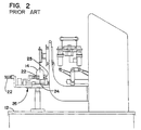
- Apparatus 11 comprises a large table or frame 12 that is horizontally disposed and supports all of the various components of apparatus 11.
- these components include an accumulator disk 13 which is filled with a plurality of vials 14 received from a conveyor not shown.
- Vials 14 are transferred from accumulator disk 13 to a transfer disk 15, and a star wheel 16 individually picks up vials 14 from the transfer disk 15 and carries them to a vial conveyor 17.
- conveyor 17 includes drive sprockets 18, 19 at opposite ends with a sprocket type conveyor belt 21 operably connected therebetween.
- a plurality of cleats 22 are mounted on and carried by conveyor belt 21, each having a V-shaped frontal recess 23 that is capable of receiving and carrying vials 14 of different diameter.
- the sequentially carried vials 14 slide along a horizontal carrier rail 24 disposed therebelow, and a side rail 25 ( Figures 2 and 6) retains each vial 14 within the V-shaped projection 23 and on the carrier rail 24.
- the position of conveyor 17 and side rail 25 may be horizontally adjusted separately by the mechanism bearing reference numeral 26 in Figure 2, which enables the apparatus to accommodate vials of different diameter and ensures that the vials travel along the proper line of machine operation.
- the vials 14 are sequentially carried by conveyor 17 to a pre-fill check weigh mechanism 27, a filling apparatus 28 consisting of a plurality of nozzles connected to a like number of pumps 29, a post-fill check weigh mechanism 31, a stoppering head 32 supplied by a stopper feeder 33, and a vial eject station 34.
- Prior art vial filling apparatus 11 is open to the surrounding environment, and is conventionally disposed in a large clean room the environment of which is maintained in a decontaminated or sterile state as is known in the art. Conventional techniques are also used to prevent contamination as operating personnel enter and leave the room, including the wearing of sterile attire such as gowns, gloves, headwear and masks.
- a vial filling apparatus embodying the invention is represented generally by the numeral 41.
- the apparatus 41 of the preferred embodiment is intended for use in the sequential filling of continuously fed vials for injectable drugs, but the invention contemplates the filling of any type of container in a sterile environment.
- apparatus 41 includes a sterilized infeed enclosure 42 through which vials 14 pass on a conveyor 48.
- Infeed enclosure 42 represents the inlet to a sterile zone, discussed below, and it is essential that the vials 14 entering at this point be in a sterilized condition.
- enclosure 42 is connected to a conventional vial washer/sterilizing tunnel 50 that receives unsterilized vials, performs a multiple step procedure that sterilizes the vials, generally including depyrogenization, and delivers sterilized vials to the conveyor 48 of sterilized infeed enclosure 42.
- the sterilized vials are transferred to an oscillating belt infeed station 43 that moves the vials to a transfer star wheel 44, which sequentially loads the vials 14 onto a principal vial conveyor 45 the basic function of which is the same as conveyor 21 of the prior art apparatus 11.
- conveyor 45 is structurally different and operates in an improved and advantageous manner.
- Conveyor 45 sequentially moves the vials 14 to a pre-fill check weigh station 46 that randomly removes a vial to establish a reference pre-fill weight.
- the vials are then carried by conveyor 45 through a filling station 47 which comprises a plurality of nozzles 49.
- Nozzles 49 are supplied by a plurality of pumps 51 described in further detail below.
- the vials 14 are moved by conveyor 45 past a post-fill check weigh station 52, which removes each of the randomly selected empty vials previously weighed at pre-fill check weigh station 46. This comparative weighing ensures that the specific amount of pharmaceutical preparation has been metered and dispensed into each vial.
- Conveyor 45 then moves the vials through a stoppering station 53 at which each of the filled vials is closed and sealed with a stopper. Vials 14 then move into an eject and outfeed station 54, where the vials are removed from conveyor 45 and carried by means not shown to a packing station.
- apparatus 41 comprises an elongated frame certain components of which are shown in this transverse sectional view. These include vertical leg members 55, a vertical cross rail member 56, a mounting plate 57 and a vertical frame support member 58 that extends between the lower and upper cross rail member 56 and plate 57, at an intermediate point between the vertical leg members 55. It is will be understood that the various components 55-58 repeat over the length of the apparatus frame.
- a vertically disposed mounting plate 59 is secured to the several frame support members 58, extending longitudinally over the length of the apparatus 41 (see also Figure 4). A portion of vertical mounting plate 59 extends above the upper cross rail members 57. A thin stainless steel sheet 61 corresponding in size to vertical mounting plate 59 is mounted thereto in spaced relation, defining an air gap 62.
- the stainless steel sheet 61 defines the elongated barrier or back plate of a stainless steel cabinet bearing general reference numeral 63, which in turn defines an internal sterile zone 64.
- the area outside cabinet 63 i.e., that portion on the left side of barrier plate 61 as viewed in Figure 5 constitutes a non-sterile zone bearing the general reference numeral 70.
- sterile cabinet 63 further comprises a front plate 65 that is shown as corresponding generally in size to the back plate 61 in the schematic representation of Figure 3.
- the front plate 65 includes several outward steps to accommodate various of the components described above.
- a cabinet top 66 and cabinet bottom 67 interconnect the back plate 61 and front plate 65, and the cabinet ends are enclosed by end plates 68, 69.
- the primary inlet to sterile zone 64 is the sterile tunnel 42 as discussed above.
- the stoppering station 53 also includes a stopper inlet or docking port 53a through which sterilized stoppers are admitted in a sterile manner as is known in the art.
- the sole outlet from sterile zone 64 is the eject and outfeed station 54, which in the preferred embodiment comprises a plurality of conventional star wheels, the first of which is disposed within sterile zone 64 and the second of which is disposed outside zone 70. Vials 14 are transferred between these first and second star wheels through a small opening in cabinet 63.
- Sterile zone 64 is preferably maintained at a pressure higher than that of the ambient surroundings to cause an outflow of air through the vial outlet between the star wheels, thus resisting contaminant entry.
- the means for maintaining such pressure which is not shown, is conventional and typically includes a supply of air that is filtered to remove contaminants.
- cabinet 63 includes a plurality of conventional glove ports 80 or other conventional means for permitting sealed access to the sterile zone 64.
- glove ports 80 are disposed at spaced points to permit operators of the apparatus 41 to have access at all points along the line of vial movement.
- a drain portion 71 of the cabinet 63 projects downwardly below the filling station 47.
- the respective bottom portions 67 adjacent the drain portion 71 are inclined downwardly toward the drain portion 71.
- the bottom of drain portion 71 defines a plurality collecting drain pans 71a-c which respectively lead to drains 72a-c.
- Each of the drains 72a-c is connected through a sealed coupling 73 to a common drain pipe 74. The purpose of these drain components is discussed in further detail below.
- each of the series of pumps 51 is of the rolling diaphragm type, such as that disclosed in U.S. Patent No. 3,880,053, and is capable of dispensing a precise amount of liquid.
- Each of the pumps 51 is horizontally disposed as shown in Figure 5, and the rolling diaphragm is actuated by a reciprocating rod 75.
- the rod 75 is reciprocated by a pivoted linkage member 76 that is connected between the rod 75 and an actuating rod 77.
- the several rods 77 for the respective pumps 51 are actuated in a precisely timed manner by a controlling mechanism 78 which is known in the art.
- Each of the pumps 51 has an inlet 81 to which an inlet tube 82 is connected.
- the several inlet tubes 82 are commonly connected to a manifold that supplies the liquid to be dispensed and filled into the vials 14.
- Each of the pumps 51 has an outlet 83 from which the precise amount of liquid is dispensed or pumped.
- Each pump outlet 83 has an outlet tube 84 connected thereto that leads to one of the nozzles 49.
- the series of nozzles 49 are mounted on a walking beam 85 that linearly reciprocates in a timed sequence relative to the moving vials 14.
- the apparatus which controls the walking beam 85 bears general reference numeral 86 and is known in the art.
- conveyor 45 includes a conveyor belt 87 having a row of sprocket holes 88 disposed along each edge.
- Conveyor belt 87 is endlessly driven by a pair of opposed sprocket wheels 89, 90 (only sprocket wheel 89 is shown in Figure 7).
- the sprocket wheels 89, 90 are turned 90 degrees and rotate about a horizontal axis as shown by reference numeral 91 in Figure 5.
- the horizontal shafts upon which drive sprocket wheels 89 rotate are not shown.
- Such shafts extend through appropriate seals in the stainless steel sheet 61 and mounting plate 59 and are driven as discussed below.
- the width of conveyor 45 is significantly reduced, as compared with the prior art conveyor 17.
- the drive means for conveyor 45 is located outside sterile cabinet 63 as discussed below, cabinet 63 and sterile zone 64 are significantly reduced in size from the standpoint of width.
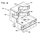
- each of the cleats 92 comprises a lower body 93 and an upper body 94.
- Lower body 93 includes a base 95 the underside of which defines a grooved track 96 that is sized and configured to overlie and be supported by conveyor belt 87.
- a counter-sunk bore 97 extends through the center of lower body 93 to receive a mounting screw (not shown) that fastens each of the cleats 92 to the conveyor belt 87.
- the top surface of lower body 93 defines a platform 98 on which one of the vials 14 may rest.
- each of the cleats 92 is offset relative to the lower body 93 to permit a vial 14 to rest in centered relation on the lower body 93.
- Upper body 94 defines lower and upper lateral supports which respectively define V-shaped recesses 100, 102, respectively.
- the recesses 100, 102 are centered relative to the lower body 93, and in the preferred embodiment are formed at a 90 degree included angle. This angle, coupled with the size of platform 98, permits each of the cleats 92 to accept vials 14 having a range of diameters. For vials having diameters that do not fall within such range, cleats 92 of a different size or a different included angle may be substituted.
- conveyor 45 includes a stationary guide rail 103 that is positioned relative to the moving cleats 92 to retain the vials 14 as shown in Figure 7.
- the lateral position of guide rail 103 may be adjusted, as described in further detail below, based on the diameter of the vials 14.
- the effective operating width of conveyor 45 is significantly less than that of conveyor 17, and corresponds essentially to the width of the cleats 92 and belt 87.
- the prior art conveyor 17 has a width that includes not only the diameter of the drive sprocket 19 and thickness of conveyor belt 21, but twice the width of the cleats 22 as well (bearing in mind the fact that the cleats 22 project laterally from both the front and back flights of the conveyor belt 21).
- the effective operating width of conveyor 17 is increased by the vials 14 which project laterally outward of the conveyor 17, whereas the vials 14 are carried in centered overlying relation to the conveyor belt 87.
- the prior art conveyor 17 requires a carrier slide rail 24, which comprises additional structure, adds to the overall size of the conveyor 17 and requires the vials 14 to slide as they are moved forwardly.
- the vials 14 rest directly and are supported in their entirety by the cleats 92, eliminating the need for the bottom slide rail 24 of the prior art and conveyor 17, avoiding friction, vibration and particle generation.
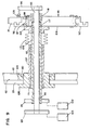
- the drive sprocket wheel 89 is carried by a mounting bracket 104 which in turn is carried by an annular mounting flange 105.
- Mounting flange 105 is secured to a telescoping adjustment tube 106 that projects through stainless steel sheet 61 and mounting plate 59.
- Telescoping adjustment tube 106 is carried for such telescopic movement by a stationary mounting tube 107 that is secured to an annular mounting collar 108.
- An annular ring 109 and annular seal 110 disposed in the air gap 62 in encircling relation to mounting collar 108 serve to maintain the sterile zone 64 in a decontaminated state.
- Bearings 111, 112 disposed between adjustment tube 106 and mounting tube 107 permit relative telescoping movement of the tube 106, and a flexible bellows 113 extends between stationary tube 107 and mounting flange 105 to permit such relative movement while sealing against contamination.
- Guide rail 103 is carried by a mounting bracket 114 that is mounted to a telescoping adjustment shaft 115.
- Shaft 115 telescopically slides within adjustment tube 106 relative to a pair of bearings 116, 117.
- a flexible bellows 118 is secured at one of its ends to the adjustment shaft 115 with the other end secured to the end of adjustment tube 106, also for the purpose of preventing the entry of contaminating matter into sterile zone 64.
- a control plate 119 is mounted to the outer end of adjustment tube 106, and a similar mounting plate 121 is mounted to the outer end of adjustment shaft 115.
- Separate actuator means 122, 123 are respectively connected to the control plates 119, 121 to effect separate adjustment of the adjustment tube 106 and shaft 115.
- the actuator means 122, 123 may be interrelated for adjustment to vials of predetermined diameter, and may also include automated means to ensure centering of the vials 14 relative to the nozzles 49.
- each of the operating stations disposed within the sterile zone 64 is driven by an actuating means that is disposed outside the sterile zone 64 (i.e., within the nonsterile zone 70).
- These various actuating means although separate, are interrelatably driven because the various operations performed within sterile zone 64 must be synchronous.
- An electric motor 131 serves as the primary drive means for the various actuating means. Separate servomotors are used for other actuating means as described below, which are operated in synchronous relation to primary drive motor 131.
- Motor 131 includes drive pulleys 132, 133 at each end.
- Drive pulley 132 drives a driven pulley 134 through an endless drive belt 135.
- Driven pulley 134 is operably connected to the bank of 16 pumps 51 in a conventional manner.
- Drive pulley 133 is connected through a drive belt 136 to a driven pulley 137, which in turn is mounted to a common drive shaft bearing the general reference numeral 138.
- Drive shaft 138 comprises a plurality of interconnected drive shaft segments 138a-e.
- Drive shaft segment 138a is connected through a right angle gear drive 139 to a pulley/timing belt configuration.
- a drive connection 142 extends through the wall of cabinet 63, connecting the pulley/timing belt 141 to the oscillating belt infeed station 43.
- the seal in the wall of cabinet 63 which bears reference numeral 143, is of the same type as the seal consisting of components 108-110 used for the lateral conveyor belt/rail adjustment of Figure 9.
- Drive shaft segment 138a is connected to shaft segment 138b through a right angle drive 144.
- a right angle drive 145 is connected between drive shaft segments 138b-c, the purpose of which is to drive the star wheel 44 through a pulley/belt configuration 146 and a drive connection 147.
- Drive connection 147 extends through mounting plate 59 of cabinet 63 through a seal of the same type as seal 143.
- Drive shaft segment 138c is connected through a pulley/belt configuration 148 to a right angle gear drive 149 having a drive pulley 151 (see also Figure 5).
- Drive pulley 151 is connected to drive the walking beam 85 through actuators 86 as described above, each of which extends through the mounting plate 59 through a seal similar to seal 143.
- Pre-fill check weigh station 46 and post-fill check weigh station 52 are separately driven by servomotors (no shown for purposes of clarity), which are operated in synchronous relation to the primary drive motor 131.
- Pre-fill check weigh apparatus 46 includes a drive connection 152
- post-fill check weigh apparatus 52 includes a drive connection 153.
- Shaft drive segment 138d is connected through a pulley/belt configuration 154 to a right angle gear drive 155 which in turn drives a pulley/belt configuration 156. This in turn is connected to a drive connection 157 that actuates a portion of the stoppering station 53. Other components of the stoppering station are driven by a separate variable speed motor.
- Shaft drive segment 138d is also connected through a gear drive 158 that drives a pulley/belt configuration 159.
- a drive connection 161 interconnects the configuration 159 through a seal, similar to seal 143, to the eject and outfeed station 54.
- Shaft drive segment 138e is connected to a right angle gear drive 162 which in turn drives a pulley/belt configuration 163.
- a drive connection 164 extends through a seal and mounting plate 59 and connects configuration 163 with drive sprocket wheel 89.
- Sprocket wheel 90 is a driven wheel and does not include a direct drive.
- the lateral adjustment mechanism shown on Figure 9 is included in the drive connection 164. This adjustment mechanism is provided at a plurality of points over the length of conveyor 45, each of which is represented by reference numeral 165.
- the actuating means for effecting lateral adjustment is not shown in Figure 4 for purposes of clarity.
- Figure 4 particularly emphasizes the significant improvement in filling apparatus 41 of a sterile zone that is significantly reduced in size, with only those components that are directly essential to the filling process located within the sterile zone. All other components, including machine drive elements, pumps, controls and the like are located outside the sterile zone.
- the resulting sterile zone is considerably smaller in size, shortens the operator's reach into the operating area while excluding potential contamination by the operator, and significantly reduces the periodic cleaning and sterilizing task.
- the sterile zone 64 within sterile cabinet 63 can be periodically cleaned and sterilized by techniques utilizing steam and/or a disinfecting liquid wash with all of the internal components in place.
- clean zone 64 may be effectively sterilized and decontaminated on a periodic basis in a manner which is far easier than decontaminating an entire room or much larger zone. This also results in a significant decrease in the cost of operating and maintaining the apparatus 41.
Landscapes
- Engineering & Computer Science (AREA)
- Mechanical Engineering (AREA)
- Basic Packing Technique (AREA)
- Filling Of Jars Or Cans And Processes For Cleaning And Sealing Jars (AREA)
- Supplying Of Containers To The Packaging Station (AREA)
- Auxiliary Devices For And Details Of Packaging Control (AREA)
Abstract
Description
This also results in a significant decrease in the cost of operating and maintaining the
Claims (23)
- An apparatus (41) for filling containers (14) in a substantially sterile environment having a frame means, enclosure means (63) carried by the frame meansa plurality of operating stations each including operating means disposed in sequential relation within the enclosure means (63)and conveyor means (45),said plurality of operating stations comprising:(a) a first container transfer means (43,44) for transferring empty containers from the inlet of the enclosure means (63) to said conveyor means(b) container filling means (47),(c) means for closing (53) said containers, and(d) second container transfer means (54) for transferring filled containers from said conveyor means to the outlet of the enclosure means (63),said apparatus further having actuating means (51,75-78,131-134,154-156) for said conveyor means and for each of said operating means, andconnecting means for operably connecting each of said actuating means with its associated operating means, characterized by:upright wall means (61) carried by the frame means and dividing the apparatus into a sterile zone (64) and a non-sterile zone (70) at least partially disposed in side-by-side relation;the enclosure means (63) cooperating with the upright wall means (61) to define the sterile zone (64);the conveyor means (45) being disposed within the sterile zone (64) for conveying containers through the sterile zone; the filling means (47) filling the containers as they are moved through the sterile zone (64) by the conveyor means;the actuating means for the container filling means (47) and the means for closing (53) said containers being disposed in the non-sterile zone (70); andthe connection means for the container filling means (47) and the means for closing (53) said containers extending through a sealed opening in the upright wall means (61).
- The apparatus of claim 1, wherein the enclosure means (63) comprises a bottom wall (67) and drain means (71) disposed within the bottom wall.
- The apparatus of claim 1, wherein the upright wall means (61) comprises a substantially vertical wall member.
- The apparatus of claim 3, wherein the substantially vertical wall member and the enclosure means (63) comprise stainless steel.
- The apparatus of claim 1, wherein the conveyor means (45) comprises:first and second drive wheels (89, 90) disposed in opposed relation, each of the drive wheels being disposed for rotation about a substantially horizontal axis;an endless conveyor belt (87) encircling the first and second drive wheels and defining upper and lower flights; anda plurality of container carrying members (92) secured to the endless conveyor belt in spaced relation.
- The apparatus of claim 5, wherein each of the container carrying members (92) is disposed in overlying relation to the outer face of the endless conveyor belt.
- The apparatus of claim 6, wherein the width of each container carrying member substantially corresponds to the width of the endless conveyor belt.
- The apparatus of claim 6, wherein each of the container carrying members (92) defines a platform sized and configured to receive and supportably carry one of the containers (14).
- The apparatus of claim 8, wherein each of the container carrying members (92) further comprises a V-shaped laterally opening recess (100, 102) disposed over the platform for providing lateral support to containers (14) of differing size.
- The apparatus of claim 9, which further comprises a guide rail (114) disposed within the sterile zone (64) adjacent the upper flight of the endless conveyor belt in opposed relation to the V-shaped laterally opening recess (100, 102) to retain the containers (14) therein.
- The apparatus of claim 10, wherein the guide rail (114) has means for supporting its lateral adjustable movement and actuating means for adjusting its position relative to the upper flight.
- The apparatus of claim 1, wherein the conveyor means (45) comprises endless conveyor belt means defining upper and lower flights, and a plurality of container carrying means secured to the endless conveyor belt means in spaced relation, each container carrying means being constructed and arranged to support and convey a container and its contents.
- The apparatus of claim 1, wherein the conveyor means (45) has supporting means for laterally adjustable movements thereof.
- The apparatus of claim 1, wherein a given operation is performed with respect to the containers at each operating station by the associated operating means.
- The apparatus of claim 14, wherein the plurality of operating stations comprise means (53) for placing a closure member on each container after it has been filled.
- The apparatus of claim 14, wherein the plurality of operating means further comprises:pre-fill check weighing means (46) to determine the weight of a selected container prior to filling; andpost-fill check weighing means (52) to determine the weight of the selected container after filling.
- The apparatus of claim 1 and 14, wherein the conveyor means (45) has adjustment actuating means for adjusting the lateral position of the same relative to the operating means.
- The apparatus of claim 17, wherein the adjustment actuating means is disposed in the non-sterile zone (70).
- The apparatus of claim 14, wherein the filling means comprises a plurality of nozzles (49) disposed in the sequential relation.
- The apparatus of claim 19, wherein the plurality of nozzles has actuating means (131-134, 51) comprising a like plurality liquid pumping means, and the connecting means therefor comprises a plurality of liquid conduits interconnecting each pumping means with its associated nozzle.
- The apparatus of claim 14, wherein the first container transfer means comprises means (42) for sterilizing the empty containers (14).
- The apparatus of claim 14, wherein the first and second container transfer means are disposed within an elongated sterile zone (64).
- The apparatus of claim 14, wherein each of the connection means extends through an opening in the upright wall means (61), and further comprising means for establishing a seal between each of the connection means and the upright wall means (61).
Applications Claiming Priority (3)
| Application Number | Priority Date | Filing Date | Title |
|---|---|---|---|
| US20504194A | 1994-03-02 | 1994-03-02 | |
| US205041 | 1994-03-02 | ||
| PCT/US1995/002406 WO1995023738A1 (en) | 1994-03-02 | 1995-02-27 | Sterile vial filling apparatus |
Publications (2)
| Publication Number | Publication Date |
|---|---|
| EP0746501A1 EP0746501A1 (en) | 1996-12-11 |
| EP0746501B1 true EP0746501B1 (en) | 2001-07-04 |
Family
ID=22760544
Family Applications (1)
| Application Number | Title | Priority Date | Filing Date |
|---|---|---|---|
| EP95911952A Expired - Lifetime EP0746501B1 (en) | 1994-03-02 | 1995-02-27 | Sterile vial filling apparatus |
Country Status (12)
| Country | Link |
|---|---|
| US (2) | US5673535A (en) |
| EP (1) | EP0746501B1 (en) |
| JP (1) | JP3255923B2 (en) |
| KR (1) | KR100365592B1 (en) |
| AT (1) | ATE202754T1 (en) |
| AU (1) | AU1932895A (en) |
| BR (1) | BR9506909A (en) |
| CA (1) | CA2184007C (en) |
| DE (1) | DE69521603T2 (en) |
| DK (1) | DK0746501T3 (en) |
| RU (1) | RU2140383C1 (en) |
| WO (1) | WO1995023738A1 (en) |
Families Citing this family (58)
| Publication number | Priority date | Publication date | Assignee | Title |
|---|---|---|---|---|
| JP3417108B2 (en) * | 1994-12-19 | 2003-06-16 | 澁谷工業株式会社 | Syringe manufacturing equipment |
| US5848515A (en) * | 1995-08-11 | 1998-12-15 | Rossi & Catelli S.P.A. | Continuous-cycle sterile bottling plant |
| US5958336A (en) * | 1996-04-26 | 1999-09-28 | Duarte; Raul | Surface sterilization device |
| US5806282A (en) * | 1997-03-28 | 1998-09-15 | Tetra Laval Holdings & Finance, Sa | Filling machine having a continuous particle monitoring system |
| US5865010A (en) * | 1997-03-28 | 1999-02-02 | Tetra Laval Holdings & Finance Sa | Filling machine having a compartmentalized clean air system enclosing the filling system thereof |
| DE19731796A1 (en) * | 1997-07-24 | 1999-01-28 | Kronseder Maschf Krones | Method and device for high-purity bottling of beverages |
| US6536188B1 (en) | 1999-02-02 | 2003-03-25 | Steuben Foods, Inc. | Method and apparatus for aseptic packaging |
| US6209591B1 (en) | 1999-02-02 | 2001-04-03 | Steuben Foods, Inc. | Apparatus and method for providing container filling in an aseptic processing apparatus |
| US6475435B1 (en) | 1999-02-02 | 2002-11-05 | Steuben Foods Incorporated | Apparatus and method for providing sterilization zones in an aseptic packaging sterilization tunnel |
| JP2000318714A (en) * | 1999-03-11 | 2000-11-21 | Toyo Jidoki Co Ltd | Intermittent container discharge device in continuous filling and packaging system |
| US6702985B1 (en) | 1999-07-15 | 2004-03-09 | Steuben Foods, Inc. | Apparatus and method for providing container interior sterilization in an aseptic processing apparatus |
| US7243689B2 (en) * | 2000-02-11 | 2007-07-17 | Medical Instill Technologies, Inc. | Device with needle penetrable and laser resealable portion and related method |
| US7669390B2 (en) | 2004-03-08 | 2010-03-02 | Medical Instill Technologies, Inc. | Method for molding and assembling containers with stoppers and filling same |
| US7707807B2 (en) * | 2004-03-08 | 2010-05-04 | Medical Instill Technologies, Inc. | Apparatus for molding and assembling containers with stoppers and filling same |
| AU2002239480B2 (en) * | 2000-10-23 | 2005-06-02 | Medical Instill Technologies, Inc. | Fluid dispenser with bladder inside rigid vial |
| US7331944B2 (en) | 2000-10-23 | 2008-02-19 | Medical Instill Technologies, Inc. | Ophthalmic dispenser and associated method |
| US7186374B2 (en) * | 2001-02-16 | 2007-03-06 | Steris Inc. | Vapor phase decontamination of containers |
| US20040020558A1 (en) * | 2001-08-14 | 2004-02-05 | Paul Stewart | Filling apparatus |
| US6799612B2 (en) * | 2001-08-14 | 2004-10-05 | The Boc Group, Inc. | Filling apparatus |
| WO2003028785A2 (en) | 2001-10-03 | 2003-04-10 | Medical Instill Technologies, Inc. | Syringe and reconstitution syringe |
| WO2003033363A1 (en) | 2001-10-16 | 2003-04-24 | Medical Instill Technologies, Inc. | Dispenser with sealed chamber and one-way valve for providing metered amounts of substances |
| US7798185B2 (en) | 2005-08-01 | 2010-09-21 | Medical Instill Technologies, Inc. | Dispenser and method for storing and dispensing sterile food product |
| JP3936608B2 (en) * | 2002-03-15 | 2007-06-27 | 健三 高木 | Drying and sealing device for sample ampules |
| ES2246599B1 (en) * | 2002-03-26 | 2006-11-01 | Grifols, S.A. | PROCEDURE AND APPLIANCE FOR PACKAGING CONTROL IN ASEPTIC CONDITIONS. |
| ITBO20020237A1 (en) * | 2002-04-24 | 2003-10-24 | Corazza Spa | MACHINE PERFECTED FOR THE PACKAGING OF A PASTY, LIQUID OR SEMI-LIQUID PRODUCT |
| AU2003251594A1 (en) * | 2002-06-19 | 2004-01-06 | Medical Instill Technologies, Inc. | Sterile filling machine having needle filling station within e-beam chamber |
| BRPI0313992B1 (en) | 2002-09-03 | 2015-07-21 | Medical Instill Tech Inc | Vial set for storing a substance and methods for making and filling it |
| US20060048844A1 (en) * | 2002-10-23 | 2006-03-09 | William Merrill | Systems, devices and methods for aseptic processing |
| ES2232269B1 (en) * | 2003-01-21 | 2006-03-01 | Grifols, S.A. | PROCEDURE FOR THE STERILE DOSAGE OF ROADS. |
| CN101596962B (en) * | 2003-01-28 | 2011-03-23 | 因斯蒂尔医学技术有限公司 | Medicament bottle with heat-sealable cap, device and method for filling the medicament bottle |
| EP1631496B1 (en) | 2003-04-28 | 2014-02-26 | Medical Instill Technologies, Inc. | Container with valve assembly for filling and dispensing substances, and apparatus and method for filling |
| DE10326618A1 (en) * | 2003-06-13 | 2005-01-05 | Khs Maschinen- Und Anlagenbau Ag, Patentabteilung | Container handling machine |
| DE10345338B4 (en) * | 2003-09-21 | 2015-08-06 | Inova Pharma Systems Gmbh | Method and device for controlled filling |
| US7707931B2 (en) * | 2004-04-06 | 2010-05-04 | West Liberty Foods, L.L.C. | Clean room food processing systems, methods and structures |
| US8141330B2 (en) | 2004-05-20 | 2012-03-27 | KNAPP Logistics Automation, Inc. | Systems and methods of automated tablet dispensing, prescription filling, and packaging |
| ES2524774T3 (en) | 2005-10-17 | 2014-12-12 | Medical Instill Technologies, Inc. | Apparatus and method of sterile demoulding |
| KR20080104266A (en) * | 2006-04-04 | 2008-12-02 | 글로리 가부시키가이샤 | Coin dispenser |
| US7281623B1 (en) * | 2006-04-18 | 2007-10-16 | Aquest Systems Corporation | Transport system including vertical rollers |
| US20070289843A1 (en) * | 2006-04-18 | 2007-12-20 | Barry Kitazumi | Conveyor System Including Offset Section |
| TW200909318A (en) * | 2006-08-25 | 2009-03-01 | Aquest Systems Corp | Conveyor transfer system |
| US20080264001A1 (en) * | 2006-12-22 | 2008-10-30 | Kinesys Automation, Inc. | System for processing cartridges |
| CN101652790B (en) | 2007-04-03 | 2013-12-11 | 国际商业机器公司 | Method and system for populating a software catalogue with related product information |
| EP2207427B1 (en) * | 2007-10-04 | 2017-05-03 | Medical Instill Technologies, Inc. | Apparatus and method for formulating and aseptically filling liquid products |
| IT1391065B1 (en) * | 2008-10-17 | 2011-11-18 | Co Ri M A S R L | MACHINE FOR FILLING VIALS |
| WO2010119130A2 (en) * | 2009-04-17 | 2010-10-21 | Gerhard Liepold | An apparatus for contained processing of substance |
| DE102011113358A1 (en) | 2011-09-15 | 2013-03-21 | Groninger & Co. Gmbh | Method and device for filling and closing pharmaceutical objects |
| CN107253545A (en) | 2012-04-13 | 2017-10-17 | 皮博士研究所有限责任公司 | Modularization pad device and method |
| WO2014145313A2 (en) | 2013-03-15 | 2014-09-18 | Dr. Py Institute, Llc | Controlled non-classified filling device and method |
| KR101652370B1 (en) * | 2015-01-28 | 2016-08-31 | 한국지질자원연구원 | Flux meter for measuring exchanges of water and mass across groundwater-surface water interface |
| JP7053456B2 (en) | 2015-09-15 | 2022-04-12 | ドクター ピー インスティチュート エルエルシー | Bulkheads that decontaminate by interacting with intrusive elements |
| USD829896S1 (en) | 2015-09-15 | 2018-10-02 | Dr. Py Institute Llc | Septum |
| US10035614B2 (en) * | 2015-09-21 | 2018-07-31 | Scholle Ipn Corporation | Method for aseptic filling of pouches |
| US20170361966A1 (en) * | 2016-06-16 | 2017-12-21 | Muffin Incorporated | Vial filling system with localized clean zone |
| GB201900818D0 (en) * | 2019-01-21 | 2019-03-13 | Mars Inc | Container processing apparatus |
| US12496400B2 (en) * | 2019-09-16 | 2025-12-16 | Stefan Brugger | Device and method for closing syringe bodies |
| US12391532B2 (en) * | 2021-04-06 | 2025-08-19 | Ronchi Mario S.P.A. | Apparatus and method for filling containers arranged in-line with collection of the fluids for washing the supply ducts and the filling heads |
| IT202200023250A1 (en) * | 2022-11-10 | 2024-05-10 | Gea Procomac Spa | A TREATMENT APPARATUS FOR TREATMENT OF CONTAINER CLOSURES |
| KR102893174B1 (en) | 2024-01-30 | 2025-11-28 | 황상철 | vial liquid filling apparatus |
Family Cites Families (80)
| Publication number | Priority date | Publication date | Assignee | Title |
|---|---|---|---|---|
| US1017038A (en) | 1911-09-21 | 1912-02-13 | Joseph H Champ | Bottle-holder for bottle-filling machines. |
| US1565371A (en) * | 1920-06-04 | 1925-12-15 | Columbia Machine And Stopper C | Bottle-capping machine |
| US1770379A (en) | 1924-08-30 | 1930-07-15 | American Can Co | Apparatus for applying inert gas to filled cans |
| US1813021A (en) | 1926-12-11 | 1931-07-07 | Gen Electric Vapor Lamp Co | Sterilizing system |
| US1920539A (en) | 1930-12-20 | 1933-08-01 | White Cap Co | Package sealing method and apparatus |
| US2154266A (en) | 1937-05-24 | 1939-04-11 | William B Willcutt | Method of and apparatus for vacuum sealing containers |
| US2517569A (en) | 1945-11-23 | 1950-08-08 | Huzenlaub Erich Gustav | Process of extracting and preserving the original flavors and food value of fruit juices |
| US2618425A (en) | 1946-09-20 | 1952-11-18 | Anchor Hocking Glass Corp | Machine for applying and sealing closures on containers |
| US2575863A (en) | 1948-03-09 | 1951-11-20 | Continental Can Co | Method of aseptic canning |
| US2685520A (en) | 1951-07-23 | 1954-08-03 | Dole Eng Co James | Apparatus and method for preserving products in sealed containers |
| US2855314A (en) | 1954-05-03 | 1958-10-07 | Dole Eng Co James | Method and apparatus for preserving products in sealed containers |
| US2870024A (en) | 1954-12-16 | 1959-01-20 | Dole Eng Co James | Preserving products in sealed containers |
| US3035886A (en) | 1957-10-07 | 1962-05-22 | Fmc Corp | Method of sterilizing |
| US3105335A (en) * | 1960-12-30 | 1963-10-01 | Fmc Corp | Apparatus for aseptic canning of food products |
| DE1215541B (en) | 1961-06-08 | 1966-04-28 | Strunck & Co Maschf H | Device for filling ampoules, bottles and similar containers |
| GB1023046A (en) | 1962-09-17 | 1966-03-16 | Stork & Co Nv | A method and installation for filling sterilized containers in a sterile space with a sterilized substance and a subsequent closure of said containers |
| US3285297A (en) | 1964-08-31 | 1966-11-15 | Milk Line Corp | Milk transfer system and apparatus |
| US3356510A (en) | 1965-11-12 | 1967-12-05 | Owens Illinois Inc | Method and apparatus for sterile packaging |
| US3527017A (en) | 1966-07-05 | 1970-09-08 | American Cyanamid Co | Sterile container filling apparatus |
| USRE30742E (en) | 1968-02-11 | 1981-09-15 | Wyard Industries, Inc. | Container depalletizing apparatus |
| US3568851A (en) * | 1968-09-12 | 1971-03-09 | Deba Zacharia Doing Business A | Yieldable antirotational means and method for a bottle support |
| US3579950A (en) | 1969-01-03 | 1971-05-25 | Borden Inc | Method of and apparatus for obviating spillage in moving containers |
| CA940891A (en) * | 1970-04-08 | 1974-01-29 | Edward R. Tascher | Medicament filling unit |
| US3619975A (en) | 1970-05-25 | 1971-11-16 | Riegel Paper Corp | Machine for packaging product in a controlled atmosphere |
| US3694997A (en) | 1970-07-10 | 1972-10-03 | A E J Corp | Food packaging machine with synchronized drive mechanism |
| US3899862A (en) | 1971-04-06 | 1975-08-19 | Lever Brothers Ltd | Sterilization of containers |
| US3766709A (en) * | 1972-01-28 | 1973-10-23 | Zausner Foods Corp | Sterilizing device for container filling machines |
| CH556269A (en) | 1972-04-17 | 1974-11-29 | Hamba Maschf | DEVICE FOR THE STERILE FILLING OF FOOD AND TOUCHES. |
| US3783581A (en) | 1972-04-18 | 1974-01-08 | Dart Ind Inc | Aseptic packaging method and machine |
| US3820300A (en) | 1972-04-28 | 1974-06-28 | Rheinmetall Gmbh | Method of and machine for producing sterile packages |
| US3761224A (en) | 1972-09-25 | 1973-09-25 | Sybron Corp | Method and apparatus for continuous ehtylene oxide sterilization |
| CH580009A5 (en) | 1973-07-04 | 1976-09-30 | Quader Ets | |
| IT992235B (en) | 1973-08-31 | 1975-09-10 | Cioni E | MACHINE FOR THE FILLING AND SAUDATURE OF CLOSELY FEED VIALS TO EXEMPORARILY SUFFER THE OPENING |
| US4014158A (en) | 1973-08-24 | 1977-03-29 | Ab Ziristor | Apparatus for filling and sealing preformed packaging containers under aseptic conditions |
| CH583609A5 (en) | 1974-11-05 | 1977-01-14 | Aluminiumwerke Ag Rorschach | |
| US4208852A (en) | 1974-11-08 | 1980-06-24 | Pont-A-Mousson S.A. | Process for the aseptic packing of products and machine employing said process |
| US4027456A (en) | 1976-01-19 | 1977-06-07 | Fmc Corporation | Air-free pouch packaging method |
| US4059903A (en) | 1976-03-31 | 1977-11-29 | Futurecraft Corporation | Controlled environment work enclosure |
| US4108509A (en) | 1977-03-18 | 1978-08-22 | Futurecraft Corporation | Controlled environment work enclosure |
| US4118914A (en) * | 1977-10-25 | 1978-10-10 | Shields Walter A | Vial assembler |
| US4327826A (en) | 1977-11-04 | 1982-05-04 | Ontario, Limited | Reciprocating pusher conveyor |
| US4200183A (en) | 1978-08-25 | 1980-04-29 | Owens-Illinois, Inc. | Apparatus for moving glass containers through a series of inspection positions |
| US4296068A (en) | 1979-02-19 | 1981-10-20 | Dai Nippon Insatsu Kabushiki Kaisha | Apparatus for sterilizing a succession of food containers or the like |
| US4263837A (en) * | 1979-03-22 | 1981-04-28 | General Electric Company | Endless conveyor system |
| US4475645A (en) | 1979-12-14 | 1984-10-09 | William P. Young Co. | Machine for applying base cups to bottles |
| US4417607A (en) | 1981-06-29 | 1983-11-29 | Scholle Corporation | Apparatus and method for aseptically filling flexible containers |
| US4530202A (en) | 1982-01-18 | 1985-07-23 | Aci Australia Limited | Container filling machine and method |
| US4549662A (en) | 1982-03-25 | 1985-10-29 | General Electric Company | Transport apparatus |
| JPS5917413A (en) * | 1982-07-15 | 1984-01-28 | Shikoku Kakoki Co Ltd | Filling and packing machine |
| EP0339756B1 (en) * | 1982-07-15 | 1991-10-16 | Shikoku Kakoki Co., Ltd. | Packaging machine |
| US4729206A (en) | 1984-11-08 | 1988-03-08 | General Foods Corporation | Method and apparatus for filling and packaging a flowable product |
| US4566293A (en) | 1984-12-03 | 1986-01-28 | The B. F. Goodrich Company | Method of sample preparation and apparatus therefor |
| US4587793A (en) | 1985-01-16 | 1986-05-13 | Home Health Care Of America, Inc. | Pharmaceutical infusion products and the process and apparatus for the making thereof |
| US4676144A (en) | 1985-12-30 | 1987-06-30 | Smithkline Beckman Corporation | Clean room system |
| US4683999A (en) * | 1986-02-03 | 1987-08-04 | Eaton Corporation | Fluid coupling device including manual engagement means |
| DE3607322A1 (en) * | 1986-03-06 | 1987-09-10 | Bosch Gmbh Robert | PASTER-FREE PACKING DEVICE |
| JPS6311163A (en) | 1986-03-24 | 1988-01-18 | 雪印乳業株式会社 | Sterilizing method and apparatus |
| JPS6344401A (en) | 1986-07-31 | 1988-02-25 | 四国化工機株式会社 | Constant tension device of web in packaging machine |
| JPH0510637Y2 (en) | 1986-09-24 | 1993-03-16 | ||
| JPS6379657A (en) | 1986-09-24 | 1988-04-09 | 四国化工機株式会社 | Container sterilizing apparatus |
| JPH074211B2 (en) | 1987-01-21 | 1995-01-25 | 実男 稲垣 | Aseptic food processing equipment |
| US4860520A (en) * | 1987-03-31 | 1989-08-29 | Adolph Coors Company | System for controlling the movement of filled and sealed containers |
| US4803827A (en) * | 1987-11-17 | 1989-02-14 | Baxter International Inc. | Means for segregating sterile and nonsterile environments in a packaging machine |
| US4869156A (en) | 1987-11-27 | 1989-09-26 | D-Con-Tainer, Inc. | Controlled environment system and method for constructing same |
| US4979347A (en) * | 1988-05-19 | 1990-12-25 | Snow Brand Milk Products Co., Ltd. | Fill- and pack in a non-germ atmosphere machine |
| JP2655883B2 (en) | 1988-07-26 | 1997-09-24 | 雪印乳業株式会社 | Aseptic packaging container and aseptic filling method |
| US5053196A (en) * | 1988-07-26 | 1991-10-01 | Snow Brand Milk Products Co., Ltd. | Method for container conveyance in germ-free filling/packaging system |
| EP0405402A3 (en) * | 1989-06-26 | 1991-03-20 | Toyo Seikan Kaisha Limited | Aseptic filling machine |
| US5258162A (en) | 1989-11-07 | 1993-11-02 | Tetra Alfa Holdings S.A. | Method of producing a gaseous hydrogen peroxide-containing sterilization fluid |
| JP2810987B2 (en) | 1990-05-11 | 1998-10-15 | 雪印乳業株式会社 | Transfer device |
| US5022165A (en) | 1990-06-29 | 1991-06-11 | The West Company, Incorporated | Sterilization tunnel |
| DE4031472C2 (en) * | 1990-10-05 | 2001-06-28 | Hoerauf Michael Maschf | Device for sterilizing, filling and closing containers with a filling opening |
| US5129212A (en) * | 1990-11-08 | 1992-07-14 | Liqui-Box/B-Bar-B Corporation | Method and apparatus for automatically filling and sterilizing containers |
| US5152968A (en) * | 1990-12-17 | 1992-10-06 | Elopak Systems A.G. | Single pass vapor generation container sterilization system |
| US5159799A (en) | 1991-10-24 | 1992-11-03 | Rising Peter E | Vial with powdered reagent |
| US5316733A (en) | 1992-04-15 | 1994-05-31 | Piper Plastics, Inc. | Clean box with sliding arms |
| DE4218941C2 (en) * | 1992-06-10 | 2002-01-24 | Bosch Gmbh Robert | Device for sterilizing cup-shaped packaging containers |
| US5406772A (en) | 1992-08-12 | 1995-04-18 | Eli Lilly And Company | Transfer conveyor system for use between sterile and non-sterile environments |
| US5534222A (en) * | 1995-07-11 | 1996-07-09 | Purity Packaging A Division Of Great Pacific Enterprises | Method for sterilizing internal surfaces of an edible liquid packaging machine |
| US5881535A (en) | 1996-04-09 | 1999-03-16 | Baxter International, Inc. | Apparatus and method for filling and sealing intravenous solution bags |
-
1995
- 1995-02-27 AT AT95911952T patent/ATE202754T1/en active
- 1995-02-27 DE DE69521603T patent/DE69521603T2/en not_active Expired - Lifetime
- 1995-02-27 KR KR1019960704779A patent/KR100365592B1/en not_active Expired - Lifetime
- 1995-02-27 BR BR9506909A patent/BR9506909A/en not_active IP Right Cessation
- 1995-02-27 JP JP52295795A patent/JP3255923B2/en not_active Expired - Lifetime
- 1995-02-27 RU RU96121356A patent/RU2140383C1/en active
- 1995-02-27 DK DK95911952T patent/DK0746501T3/en active
- 1995-02-27 CA CA002184007A patent/CA2184007C/en not_active Expired - Lifetime
- 1995-02-27 EP EP95911952A patent/EP0746501B1/en not_active Expired - Lifetime
- 1995-02-27 WO PCT/US1995/002406 patent/WO1995023738A1/en not_active Ceased
- 1995-02-27 AU AU19328/95A patent/AU1932895A/en not_active Abandoned
-
1997
- 1997-01-02 US US08/777,992 patent/US5673535A/en not_active Ceased
-
1999
- 1999-10-07 US US09/414,913 patent/USRE37471E1/en not_active Expired - Lifetime
Also Published As
| Publication number | Publication date |
|---|---|
| DE69521603D1 (en) | 2001-08-09 |
| BR9506909A (en) | 1997-09-16 |
| EP0746501A1 (en) | 1996-12-11 |
| ATE202754T1 (en) | 2001-07-15 |
| CA2184007A1 (en) | 1995-09-08 |
| DE69521603T2 (en) | 2002-05-08 |
| USRE37471E1 (en) | 2001-12-18 |
| CA2184007C (en) | 1998-12-01 |
| JPH09509914A (en) | 1997-10-07 |
| US5673535A (en) | 1997-10-07 |
| AU1932895A (en) | 1995-09-18 |
| JP3255923B2 (en) | 2002-02-12 |
| DK0746501T3 (en) | 2001-09-24 |
| WO1995023738A1 (en) | 1995-09-08 |
| RU2140383C1 (en) | 1999-10-27 |
| KR100365592B1 (en) | 2003-03-06 |
Similar Documents
| Publication | Publication Date | Title |
|---|---|---|
| US5673535A (en) | Vial filling apparatus | |
| EP3041748B1 (en) | System and method of manufacture of a flexible container | |
| DE60202995T2 (en) | Machine for aseptic filling | |
| JP5054192B2 (en) | Active sterilization zone for container filling | |
| CN101049899B (en) | Seal assembly for sealing transitions between machine elements and equipment with the seal assembly | |
| US3336722A (en) | Method and installation for filling sterilized containers in a sterile space with a sterilized substance and subsequent closure of said containers | |
| EP1729825B1 (en) | Apparatus for sterilizing containers of plastic material and for filling them with liquid substances | |
| JP2003118793A (en) | Equipment for handling containers | |
| US8845977B2 (en) | Apparatus for transporting containers | |
| USRE38747E1 (en) | Vial filling apparatus | |
| US4730435A (en) | Sterile docking system for filling IV bags | |
| DE19909826A1 (en) | Method to sterilise containers, e.g. drinks containers; involves conveying containers in filling unit, where they are plasma-sterilised in several units before being filled by filling device | |
| US6024917A (en) | Sterilization device and method for sterilizing objects | |
| US5865010A (en) | Filling machine having a compartmentalized clean air system enclosing the filling system thereof | |
| EP1850883A1 (en) | Device for feeding sterile closures, which are delivered in bags, into a filling system for bottles or the like | |
| EP1468918A1 (en) | Aseptic vial filling apparatus | |
| JPH0629080B2 (en) | Aseptic filling device | |
| US12091203B2 (en) | Apparatus for filling containers in a sterile environment | |
| MXPA96003727A (en) | Appliance to fill esteri bottles | |
| DE69209302T2 (en) | Process for sterilizing, filling and closing rigid containers with lids in an aseptic environment and apparatus for performing the process | |
| JPH0329703A (en) | Rotary type aseptic filling apparatus | |
| WO2025163549A1 (en) | A regulating valve for sealing process chambers | |
| CN111942678A (en) | Plastic packaging equipment for boxed medicine | |
| JP3022456B2 (en) | Steamer and steamer for solid foods | |
| DE102014117032A1 (en) | Device for sterilizing objects |
Legal Events
| Date | Code | Title | Description |
|---|---|---|---|
| PUAI | Public reference made under article 153(3) epc to a published international application that has entered the european phase |
Free format text: ORIGINAL CODE: 0009012 |
|
| 17P | Request for examination filed |
Effective date: 19960919 |
|
| AK | Designated contracting states |
Kind code of ref document: A1 Designated state(s): AT BE CH DE DK FR GB IE IT LI NL SE |
|
| 17Q | First examination report despatched |
Effective date: 19971125 |
|
| GRAG | Despatch of communication of intention to grant |
Free format text: ORIGINAL CODE: EPIDOS AGRA |
|
| GRAG | Despatch of communication of intention to grant |
Free format text: ORIGINAL CODE: EPIDOS AGRA |
|
| GRAG | Despatch of communication of intention to grant |
Free format text: ORIGINAL CODE: EPIDOS AGRA |
|
| GRAH | Despatch of communication of intention to grant a patent |
Free format text: ORIGINAL CODE: EPIDOS IGRA |
|
| GRAH | Despatch of communication of intention to grant a patent |
Free format text: ORIGINAL CODE: EPIDOS IGRA |
|
| GRAA | (expected) grant |
Free format text: ORIGINAL CODE: 0009210 |
|
| AK | Designated contracting states |
Kind code of ref document: B1 Designated state(s): AT BE CH DE DK FR GB IE IT LI NL SE |
|
| REF | Corresponds to: |
Ref document number: 202754 Country of ref document: AT Date of ref document: 20010715 Kind code of ref document: T |
|
| REG | Reference to a national code |
Ref country code: CH Ref legal event code: EP |
|
| REG | Reference to a national code |
Ref country code: IE Ref legal event code: FG4D |
|
| REF | Corresponds to: |
Ref document number: 69521603 Country of ref document: DE Date of ref document: 20010809 |
|
| ET | Fr: translation filed | ||
| REG | Reference to a national code |
Ref country code: DK Ref legal event code: T3 |
|
| ITF | It: translation for a ep patent filed | ||
| REG | Reference to a national code |
Ref country code: CH Ref legal event code: NV Representative=s name: E. BLUM & CO. PATENTANWAELTE |
|
| REG | Reference to a national code |
Ref country code: GB Ref legal event code: IF02 |
|
| PLBE | No opposition filed within time limit |
Free format text: ORIGINAL CODE: 0009261 |
|
| STAA | Information on the status of an ep patent application or granted ep patent |
Free format text: STATUS: NO OPPOSITION FILED WITHIN TIME LIMIT |
|
| 26N | No opposition filed | ||
| REG | Reference to a national code |
Ref country code: CH Ref legal event code: PFA Owner name: ROBERT BOSCH PACKAGING TECHNOLOGY, INC. Free format text: TL SYSTEMS CORPORATION#8700 WYOMING AVENUE NORTH#MINNEAPOLIS, MN 55445-1840 (US) -TRANSFER TO- ROBERT BOSCH PACKAGING TECHNOLOGY, INC.#8700 WYOMING AVENUE SOUTH#MINNEAPOLIS, MN 55445-1840 (US) |
|
| NLT1 | Nl: modifications of names registered in virtue of documents presented to the patent office pursuant to art. 16 a, paragraph 1 |
Owner name: ROBERT BOSCH PACKAGING TECHNOLOGY, INC. |
|
| REG | Reference to a national code |
Ref country code: FR Ref legal event code: CD |
|
| REG | Reference to a national code |
Ref country code: CH Ref legal event code: PFA Owner name: ROBERT BOSCH PACKAGING TECHNOLOGY, INC. Free format text: ROBERT BOSCH PACKAGING TECHNOLOGY, INC.#8700 WYOMING AVENUE SOUTH#MINNEAPOLIS, MN 55445-1840 (US) -TRANSFER TO- ROBERT BOSCH PACKAGING TECHNOLOGY, INC.#8700 WYOMING AVENUE SOUTH#MINNEAPOLIS, MN 55445-1840 (US) |
|
| PGFP | Annual fee paid to national office [announced via postgrant information from national office to epo] |
Ref country code: DK Payment date: 20140221 Year of fee payment: 20 Ref country code: NL Payment date: 20140220 Year of fee payment: 20 Ref country code: SE Payment date: 20140220 Year of fee payment: 20 Ref country code: IE Payment date: 20140221 Year of fee payment: 20 Ref country code: CH Payment date: 20140220 Year of fee payment: 20 |
|
| PGFP | Annual fee paid to national office [announced via postgrant information from national office to epo] |
Ref country code: FR Payment date: 20140218 Year of fee payment: 20 Ref country code: BE Payment date: 20140219 Year of fee payment: 20 Ref country code: AT Payment date: 20140219 Year of fee payment: 20 Ref country code: IT Payment date: 20140225 Year of fee payment: 20 |
|
| PGFP | Annual fee paid to national office [announced via postgrant information from national office to epo] |
Ref country code: GB Payment date: 20140220 Year of fee payment: 20 |
|
| PGFP | Annual fee paid to national office [announced via postgrant information from national office to epo] |
Ref country code: DE Payment date: 20140417 Year of fee payment: 20 |
|
| REG | Reference to a national code |
Ref country code: DE Ref legal event code: R071 Ref document number: 69521603 Country of ref document: DE |
|
| REG | Reference to a national code |
Ref country code: DK Ref legal event code: EUP Effective date: 20150227 |
|
| REG | Reference to a national code |
Ref country code: NL Ref legal event code: V4 Effective date: 20150227 |
|
| REG | Reference to a national code |
Ref country code: CH Ref legal event code: PL |
|
| REG | Reference to a national code |
Ref country code: GB Ref legal event code: PE20 Expiry date: 20150226 |
|
| REG | Reference to a national code |
Ref country code: IE Ref legal event code: MK9A |
|
| REG | Reference to a national code |
Ref country code: SE Ref legal event code: EUG |
|
| REG | Reference to a national code |
Ref country code: AT Ref legal event code: MK07 Ref document number: 202754 Country of ref document: AT Kind code of ref document: T Effective date: 20150227 |
|
| PG25 | Lapsed in a contracting state [announced via postgrant information from national office to epo] |
Ref country code: IE Free format text: LAPSE BECAUSE OF EXPIRATION OF PROTECTION Effective date: 20150227 |
|
| PG25 | Lapsed in a contracting state [announced via postgrant information from national office to epo] |
Ref country code: GB Free format text: LAPSE BECAUSE OF EXPIRATION OF PROTECTION Effective date: 20150226 |