EP0745740B1 - Procédé d'assemblage d'un élément de construction sur une charpente métallique et ouvrage ainsi obtenu - Google Patents
Procédé d'assemblage d'un élément de construction sur une charpente métallique et ouvrage ainsi obtenu Download PDFInfo
- Publication number
- EP0745740B1 EP0745740B1 EP96401148A EP96401148A EP0745740B1 EP 0745740 B1 EP0745740 B1 EP 0745740B1 EP 96401148 A EP96401148 A EP 96401148A EP 96401148 A EP96401148 A EP 96401148A EP 0745740 B1 EP0745740 B1 EP 0745740B1
- Authority
- EP
- European Patent Office
- Prior art keywords
- construction element
- contact means
- structural framework
- orifice
- assembly position
- Prior art date
- Legal status (The legal status is an assumption and is not a legal conclusion. Google has not performed a legal analysis and makes no representation as to the accuracy of the status listed.)
- Expired - Lifetime
Links
- 238000000034 method Methods 0.000 title claims abstract description 59
- 239000000463 material Substances 0.000 claims abstract description 48
- 229920002994 synthetic fiber Polymers 0.000 claims abstract description 7
- 239000011248 coating agent Substances 0.000 claims abstract description 6
- 238000000576 coating method Methods 0.000 claims abstract description 6
- 230000001050 lubricating effect Effects 0.000 claims abstract 2
- 238000010276 construction Methods 0.000 claims description 58
- 238000005266 casting Methods 0.000 claims description 22
- 238000009415 formwork Methods 0.000 claims description 21
- 239000002184 metal Substances 0.000 claims description 18
- 239000004567 concrete Substances 0.000 claims description 14
- 230000002787 reinforcement Effects 0.000 claims description 7
- 238000003466 welding Methods 0.000 claims description 7
- 238000011065 in-situ storage Methods 0.000 claims description 6
- -1 polyethylenes Polymers 0.000 claims description 6
- 239000004568 cement Substances 0.000 claims description 5
- 238000003754 machining Methods 0.000 claims description 5
- 239000004952 Polyamide Substances 0.000 claims description 4
- 239000004698 Polyethylene Substances 0.000 claims description 4
- 239000000314 lubricant Substances 0.000 claims description 4
- 229920002647 polyamide Polymers 0.000 claims description 4
- 229920000573 polyethylene Polymers 0.000 claims description 4
- 229920000915 polyvinyl chloride Polymers 0.000 claims description 4
- 239000004800 polyvinyl chloride Substances 0.000 claims description 4
- 229910000831 Steel Inorganic materials 0.000 claims description 3
- 238000004026 adhesive bonding Methods 0.000 claims description 3
- 230000000295 complement effect Effects 0.000 claims description 3
- 238000001125 extrusion Methods 0.000 claims description 3
- 239000003973 paint Substances 0.000 claims description 3
- 229920002635 polyurethane Polymers 0.000 claims description 3
- 239000004814 polyurethane Substances 0.000 claims description 3
- 238000007789 sealing Methods 0.000 claims description 3
- 239000007787 solid Substances 0.000 claims description 3
- 239000010959 steel Substances 0.000 claims description 3
- 238000003856 thermoforming Methods 0.000 claims description 3
- 230000006835 compression Effects 0.000 claims description 2
- 238000007906 compression Methods 0.000 claims description 2
- 238000005553 drilling Methods 0.000 claims description 2
- 239000012530 fluid Substances 0.000 claims description 2
- 239000004519 grease Substances 0.000 claims description 2
- 239000011429 hydraulic mortar Substances 0.000 claims description 2
- 235000000396 iron Nutrition 0.000 claims description 2
- 238000000465 moulding Methods 0.000 claims description 2
- 229920001343 polytetrafluoroethylene Polymers 0.000 claims description 2
- 239000004810 polytetrafluoroethylene Substances 0.000 claims description 2
- 238000005096 rolling process Methods 0.000 claims description 2
- 230000035882 stress Effects 0.000 claims 4
- 230000003014 reinforcing effect Effects 0.000 claims 2
- 230000032683 aging Effects 0.000 claims 1
- 238000005336 cracking Methods 0.000 claims 1
- 238000000151 deposition Methods 0.000 claims 1
- 150000002118 epoxides Chemical class 0.000 claims 1
- 239000011888 foil Substances 0.000 claims 1
- 230000000284 resting effect Effects 0.000 claims 1
- 229910001220 stainless steel Inorganic materials 0.000 claims 1
- OKTJSMMVPCPJKN-UHFFFAOYSA-N Carbon Chemical compound [C] OKTJSMMVPCPJKN-UHFFFAOYSA-N 0.000 abstract description 2
- 229910002804 graphite Inorganic materials 0.000 abstract description 2
- 239000010439 graphite Substances 0.000 abstract description 2
- CWQXQMHSOZUFJS-UHFFFAOYSA-N molybdenum disulfide Chemical compound S=[Mo]=S CWQXQMHSOZUFJS-UHFFFAOYSA-N 0.000 abstract 1
- 125000006850 spacer group Chemical group 0.000 abstract 1
- 210000000056 organ Anatomy 0.000 description 8
- 238000004519 manufacturing process Methods 0.000 description 6
- 238000007711 solidification Methods 0.000 description 6
- 230000008023 solidification Effects 0.000 description 6
- 230000035800 maturation Effects 0.000 description 4
- 239000004593 Epoxy Substances 0.000 description 2
- 238000009434 installation Methods 0.000 description 2
- 239000004570 mortar (masonry) Substances 0.000 description 2
- 238000007493 shaping process Methods 0.000 description 2
- 230000035939 shock Effects 0.000 description 2
- 240000008042 Zea mays Species 0.000 description 1
- 230000004075 alteration Effects 0.000 description 1
- 239000002131 composite material Substances 0.000 description 1
- 230000007797 corrosion Effects 0.000 description 1
- 238000005260 corrosion Methods 0.000 description 1
- 238000005520 cutting process Methods 0.000 description 1
- 238000009826 distribution Methods 0.000 description 1
- 125000003700 epoxy group Chemical group 0.000 description 1
- 230000004927 fusion Effects 0.000 description 1
- 238000000227 grinding Methods 0.000 description 1
- 229920001903 high density polyethylene Polymers 0.000 description 1
- 239000004700 high-density polyethylene Substances 0.000 description 1
- 238000002513 implantation Methods 0.000 description 1
- 238000005304 joining Methods 0.000 description 1
- 230000007774 longterm Effects 0.000 description 1
- 238000005461 lubrication Methods 0.000 description 1
- 230000003647 oxidation Effects 0.000 description 1
- 238000007254 oxidation reaction Methods 0.000 description 1
- 238000005192 partition Methods 0.000 description 1
- 235000011837 pasties Nutrition 0.000 description 1
- 230000002093 peripheral effect Effects 0.000 description 1
- 229920003023 plastic Polymers 0.000 description 1
- 239000004033 plastic Substances 0.000 description 1
- 229920000647 polyepoxide Polymers 0.000 description 1
- 239000011178 precast concrete Substances 0.000 description 1
Images


Classifications
-
- E—FIXED CONSTRUCTIONS
- E01—CONSTRUCTION OF ROADS, RAILWAYS, OR BRIDGES
- E01D—CONSTRUCTION OF BRIDGES, ELEVATED ROADWAYS OR VIADUCTS; ASSEMBLY OF BRIDGES
- E01D19/00—Structural or constructional details of bridges
- E01D19/12—Grating or flooring for bridges; Fastening railway sleepers or tracks to bridges
- E01D19/125—Grating or flooring for bridges
-
- E—FIXED CONSTRUCTIONS
- E04—BUILDING
- E04B—GENERAL BUILDING CONSTRUCTIONS; WALLS, e.g. PARTITIONS; ROOFS; FLOORS; CEILINGS; INSULATION OR OTHER PROTECTION OF BUILDINGS
- E04B5/00—Floors; Floor construction with regard to insulation; Connections specially adapted therefor
- E04B5/16—Load-carrying floor structures wholly or partly cast or similarly formed in situ
- E04B5/17—Floor structures partly formed in situ
- E04B5/23—Floor structures partly formed in situ with stiffening ribs or other beam-like formations wholly or partly prefabricated
- E04B5/29—Floor structures partly formed in situ with stiffening ribs or other beam-like formations wholly or partly prefabricated the prefabricated parts of the beams consisting wholly of metal
-
- E—FIXED CONSTRUCTIONS
- E01—CONSTRUCTION OF ROADS, RAILWAYS, OR BRIDGES
- E01D—CONSTRUCTION OF BRIDGES, ELEVATED ROADWAYS OR VIADUCTS; ASSEMBLY OF BRIDGES
- E01D2101/00—Material constitution of bridges
- E01D2101/20—Concrete, stone or stone-like material
- E01D2101/24—Concrete
- E01D2101/26—Concrete reinforced
- E01D2101/268—Composite concrete-metal
-
- E—FIXED CONSTRUCTIONS
- E01—CONSTRUCTION OF ROADS, RAILWAYS, OR BRIDGES
- E01D—CONSTRUCTION OF BRIDGES, ELEVATED ROADWAYS OR VIADUCTS; ASSEMBLY OF BRIDGES
- E01D2101/00—Material constitution of bridges
- E01D2101/20—Concrete, stone or stone-like material
- E01D2101/24—Concrete
- E01D2101/26—Concrete reinforced
- E01D2101/28—Concrete reinforced prestressed
- E01D2101/285—Composite prestressed concrete-metal
Definitions
- the invention relates to a method of assembling one or more construction elements on a metal frame, and a structure as well got.
- metal frames as a support for a construction element obtained by casting a setting material such as concrete, cement, or mortar.
- a bridge or a floor of building a lattice frame of beams, profiles or boxes, on which is rigidly fixed a concrete slab.
- Document US-4,972,537 describes a composite panel intended for a bridge and supported by a beam, the panel comprising a structure rectangular, a reinforcement grid, structural elements and channels, as well as a concrete formwork, which traps the grid and partially the structural elements, the structural elements and the channels being provided a locking hole through which extends a locking rod engaging in a loop fixed to the beam.
- Document FR-2 698 111 describes a process for producing an apron bridge, according to which beams provided with reliefs are put in place attachment, we drag on the parts thereof without reliefs for fixing precast concrete elements before joining them with beams.
- connection is stiffened from the start of taking the poured material or bonding concrete, which generates internal stresses, both in the building element (s) and in the frame.
- the invention aims to overcome in particular the drawbacks mentioned upper.
- a first object of the invention is a method of assembly on a metal frame of at least one building element such as slab or wall, obtained by casting and then taking a material, for example concrete or cement.
- Another object of the invention is a work in which at least one construction element and a frame are assembled according to the above process.
- Each structure 1 is of the type comprising a metal frame 2, and at least one construction element 3, carried by the frame 2.
- Frame 2 can therefore include a or several open or unopened boxes, wire mesh, beams or profile.
- Book 1 may include one ( Figure 4) or more ( Figure 1) construction elements 3, obtained by casting, in particular in a formwork, of a setting material.
- each element 3 is not limited to the examples described and illustrated.
- It can be a building slab or floor, an apron of bridge, or any other structure such as wall, partition, to which the invention may apply.
- the material to be taken is generally concrete, cement or the like.
- Reinforcement reinforcements 4 are generally embedded in the material of element 3. And the construction element can be constituted of several parts comprising different materials.
- FIG. 2 illustrates an example of work 1 in which at least one construction element 3, here a substantially horizontal concrete slab, is assembled by connection or rigid fixing, to a frame 2.
- at least one construction element 3 here a substantially horizontal concrete slab, is assembled by connection or rigid fixing, to a frame 2.
- the frame 2 has a wall 5, one face of which is stretched facing of element 3.
- the element 3 has a surface 6, intended to be stretched opposite of the wall 5, when the element 3 is in a so-called assembly position, in which it will be rigidly connected to the frame 2.
- the opposite parts of the wall 5 and the corresponding surface 6 define a definitive support zone of the element 3 on the frame 2.
- the element 3 also includes at least one orifice 7 which passes through it right through, here roughly perpendicular to the final support area.
- this area can be of the order of 1,200 to 10,000 mm 2 .
- the reduced area of the orifices 7 does not reduce the mechanical strength of item 3 only to a limited extent.
- the through holes 7 are generally shaped cylindrical.
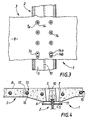
- the orifice 7a is formed in the form of a cylinder with a base circular.
- the orifice 7b is of cylindrical shape with a base substantially oblong. Other forms can be provided.
- FIG. 5 there is seen an orifice 7, the longitudinal direction XX ′ of which is substantially perpendicular to the final bearing surface 6.
- the orifice 7 is of flared shape in the direction X-X ', so that its cross-sectional area transverse perpendicular to the direction X-X ', increases with distance from the surface 6.
- the through holes 7 in FIG. 5 are delimited by a jacket 9.
- One or more orifices 7 may be provided with such a jacket 9.
- the jacket 9 is used during the casting of 1, element 3, and constitutes a complementary form which is arranged in a formwork of manufacture of the element 3, so that one or more orifices 7 are provided when casting this element.
- the jacket 9 is therefore a form of formwork, for example example obtained from a tubular section, or by shaping a cutting of wire mesh, sheet or strip.
- one or more orifices 7 can be provided in element 3, subsequent to the setting of the cast material.
- they can be obtained by drilling or any other suitable type of machining.
- the reference 10 designates, so general, means of contact with sliding.
- the contact means 10 are provided to be interposed between the frame 2 and building element 3, in the assembly position.
- the contact means 10 provide a space for connection 11 between the final bearing surface 6 of the element 3, and the opposite face of the wall 5 of permanent support on the frame 2.
- each orifice 7 opens into a space of fitting 11.
- an assembly between an element 3 and a frame 2 has a single connection space 11, or several contiguous spaces 11 or no.
- the orifices 7 are arranged in a linear fashion.
- a plurality or series of orifices 7 are provided here. small area.
- the arrangement of the orifices 7 can be provided for various reasons by example by “clouds” or zones grouping several "punctual" orifices 7 neighbors spread geometrically.
- the orifices 7 are arranged with a density (at more or less close proximity to each other) determined according to shear forces that the stops will have to undergo. So a high density is provided at the support points of the element, and a lower density at a distance of these supports. The distribution of the orifices 7 is therefore made proportional to the constraints, in order to avoid concentrations of harmful efforts.
- the orifices 7 are formed at regular intervals according to a provision in rectilinear series. To the right of each final support zone, and therefore of each wall 5 of the frame 2, the orifices 7 are arranged according to parallel lines, here 2 in number.
- the spacings between the lines as well as between the different orifices 7 of each line is calculated to provide as many orifices 7 as necessary, insofar as the mechanical resistance of element 3 remains within acceptable limits.
- the sliding contact means 10 provide a connection space 11 whose thickness Y, measured according to the direction X-X ', is of the order of 5 to 50 mm.
- containment members 12 are arranged between surface 6 and wall 5 in order to delimit and seal so substantially tight fitting space 11.
- the containment members 12 can be of any material allowing a substantially waterproof caulking. It can be a torus in matter flexible synthetic, which can be left within or removed from the structure 1, once the assembly of the frame 2 and each element 3 is finished.
- a common connection space is extended to the right of several elements 3.
- a containment member 12 can delimit, at least in part, several connection spaces 11, for example between several elements 3 and a single frame.
- connection spaces 11 are confined so as to be capable of being at least partially filled with a bonding material 13.
- This filling can be carried out by the end of the orifices 7 opening into the useful face 8, since each connection space 11 is connected with one or more orifices 7.
- the step of confining the space 11 by the members 12 is carried out, according to the examples of FIGS. 4 to 7, once the frame 2 has been put in place, and the element 3 is in the assembly position .
- containment members 12 may be arranged in the formwork of the element 3, making provision to spare the or the connection spaces 11, cores of complementary shape.
- the formwork cavity of the element 3 can be in part delimited by a confinement member 12.
- organs 12 are kept within the structure 1, they participate in the protection of the connection between the frame 2 and the element 3, especially against humidity.
- the armatures 4 of element 3 can be fully embedded, and stretched distance from the orifices 7.
- each reference 14 designates a stop rigidly fixed to the frame 2.
- Each stop 14 is fixed to the frame 2, so as to be tensioned inside a connection space 11 and a through hole 7.
- a clearance is provided around each stop 14, in the connection space 11 as well as in the opening 7 which opens there.
- This game can be around 20 to 50 mm. Its function is to allow the passage of the connecting material 13 in each orifice 7 and each connection space 11, so as to form a block solid in which the stop 14 is embedded.
- the stops 14 are in the form of metal connectors or studs, generally extended in the direction longitudinal X-X '. One end of each stop 14 is extended in a connection space 11, and fixed to the face of the wall 5 opposite the surface 6.
- This fixing step can be carried out by arc welding, possibly using the stop 14 as an electrode, in order to cause the fusion and rigid fixing of the stop 14 and the frame 2.
- the rigid fixing operation of at least one stop 14 on the frame 2 can be carried out before or after the construction element 3 has been installed assembly position.
- this fixing can be carried out before the element 3 is obtained by casting in situ in a formwork arranged on the frame 2.
- each stop 14 is extended in the orifice 7 corresponding, and may have its free end opposite to the submerged frame 2 in the material 13. Alternatively, the free end of a stop 14 can project of face 8.
- the reference 15 designates prestressing systems for item 3.
- each system 15 comprises an internal cable 16, extended in element 3.
- Each internal cable 16 is housed in a sheath 17, itself embedded in element 3.
- prestressing systems can be provided, for example, by bar, with external cable or without sheath.
- structure 1 has several elements 3, the same system of prestressing 15 can compress several of these elements.
- One function of the means 10 is to allow movement and / or deformations of the building element with respect to the frame, when this element 3 rests in the assembly position on the frame by through the means 10.
- the contact area of the contact means 10 is extended surface weak, while their coefficient of friction is less than that which is obtained by direct contact between the construction element 3 and the frame 2.
- the "coefficient of friction of the contact means 10" is the coefficient friction between a means 10 and a frame 2 given. It is a function times of the material of the means 10 and that of the frame part 2 on which rest the contact means, dry or with lubrication.
- the contact area of the contact means 10 is determined to be extended over 20% at most of the assembly area defined by the surface permanent support 6 and wall 5 of the frame 2.
- this support area is only limited by resistance own mechanical means 10.
- the means 10 In fact, being interposed between the frame and the element 3, the means 10 must support the latter.
- the means 10 support the element 3 at least in part, and until the bonding material 13 has not finished setting.
- the contact means 10 may include at least one sliding in synthetic material, for example produced by molding, thermoforming or extrusion.
- the synthetic material of this organ can be chosen from among the epoxies, polyurethanes, polyethylenes (possibly high density), polyamides, polyvinyl chloride and polytetrafluoroethylene.
- At least one member of the contact means 10 can be metallic, for example example produced by machining, profiling, lapping, grinding, rolling or coming foundry.
- the choice of the metal for a sliding member may include among the steels, mainly stainless, cast irons or any other metal capable of withstand the constraints mentioned above, while ensuring a coefficient of appropriate friction.
- the contact means 10 can be interposed in the form of a coating.
- a lubricant such as grease, paint, material coating initially fluid, pasty, or in the form of a deformable film can be applied on frame 2 or element 3.
- Such a coating therefore forms part of the means 10.
- a lubricant such as molyphene graphite or bi-sulfide, it can be applied in particular to other means 10, for example a sliding surface.
- the contact means 10 are at least partly arranged and rigidly integral either with the element 3 or with the frame 2.
- the contact means 10 comprise a member rigidly fixed to the frame 2, and a member rigidly fixed to the element 3.
- Such rigid fixing can be carried out, depending on the nature, shape and destination of the contact means 10, by welding, gluing, sealing, press-in, mechanical connection added such as screwing, riveting or the like.
- the contact means 10 are arranged when obtaining by casting the building element 3, by implantation of a contact in a formwork.
- such an organ can partially delimit the cavity of casting, so as to project after formwork removal of the element 3 thus obtained.
- the sliding member of FIG. 6 is in the form of an open envelope, the concavity of which is filled with the material of element 3.
- Such an organ can be obtained from a sheet of polyethylene or polyvinyl chloride, by thermoforming an elongated strip and continues, in order to give it a section in a plane parallel to the axis XX 'and perpendicular to surface 6, in the shape of an overturned omega.
- a member of the means 10 has a hollow shape, and is arranged so as to allow poured material and / or bonding material to be poured into its cavity, in order to fix it to element 3.
- the sliding member of the means 10 is sealed in element 3, so as to project from surface 6.
- This sealing is obtained by providing concavities in the part of the organ of sliding intended to be embedded in the material of element 3.
- This type of fixing by taking the material of element 3 around shapes such as peripheral throat, shoulder or the like, is suitable for discreetly shaped sliding members, such as block, pad, foot or shoe (figure 1).
- materials such as high density polyethylene or polyamide can be chosen for the sliding member.
- Its shaping can be obtained by extrusion and / or machining, in particular.
- a sliding strip of the means 10 is rigidly fixed for example by screwing, welding or gluing, to the wall 5 of the frame 2.
- Such a band here oriented in the longitudinal direction of the beam which includes wall 5, can be made from a steel sheet stainless polished, welded or glued to the frame 2.
- such a strip can be made of plastic such that polyethylene, polyamide, polyvinyl chloride or potytetrafluoethylene.
- the means sliding 10 provided on the frame 2 can be continuous or discontinuous.
- the contact means 10 are preferably arranged in the direction of this sliding, in general along the longitudinal direction of the frame, and over a distance corresponding to that which must be traversed by sliding by each element.
- the metal sliding can be rectified, lapped or polished.
- a layer of lubricant can be added to it.
- a high resistance paint such as epoxy or polyurethane.
- the first example concerns the case where a construction element single must be assembled to a frame. And where the building element is carried out in situ.
- the bonding material 13 has a grip dimensionally stable, that is to say a limited or even zero shrinkage during its solidification.
- a hydraulic mortar can be used as the link 13.
- the third example this process aims at assembling several prefabricated and contiguous building elements, on a single frame. This process can be used to obtain work 1 of figure 1.
- a compression reserve is provided which prevents the appearance, after solidification, cracks from internal stresses traction, born of long-term phenomena, such as deferred withdrawal or "creep".
- element 3 can be kept compressed, whatever the case of service load of structure 1, thus ensuring a excellent durability of the structure 1.
Landscapes
- Engineering & Computer Science (AREA)
- Architecture (AREA)
- Civil Engineering (AREA)
- Structural Engineering (AREA)
- Physics & Mathematics (AREA)
- Electromagnetism (AREA)
- Forms Removed On Construction Sites Or Auxiliary Members Thereof (AREA)
- Flanged Joints, Insulating Joints, And Other Joints (AREA)
- Joining Of Building Structures In Genera (AREA)
- Automobile Manufacture Line, Endless Track Vehicle, Trailer (AREA)
Description
Alternativement, par exemple si l'élément 3 est obtenu par coulée est situé directement sur la charpente 2 et en position d'assemblage, des organes de confinement 12 pourront être disposés dans le coffrage de l'élément 3, en prévoyant pour ménager le ou les espaces de raccord 11, des noyaux de forme complémentaire.
- mise en place de la charpente 2 ;
- si nécessaire, agencement d'organes de glissements 10 sur la charpente ;
- montage du coffrage sur la charpente 2 ;
- si nécessaire, agencement dans le coffrage de noyaux pour les orifices 7, les espaces de raccordement 11, et agencement dans le coffrage des moyens de contact 10 ;
- disposition d'armatures de ferraillage 4 ;
- coulée dans le coffrage d'un matériau apte à se solidifier par prisé (béton, ciment, mortier, etc);
- maturation du matériau coulé jusqu'à une valeur de prise et de retrait suffisamment stable ;
- décoffrage ;
- si nécessaire, précontrainte de l'élément 3 par les systèmes 15, éventuellement en ayant prévu de positionner les gaines 16 dans le coffrage ;
- fixation des butées 14 ;
- mise en place des organes de confinement 12 ;
- coulée dans les espaces de raccord 11 et les orifices 7 d'un matériau de liaison 13 ; et
- maturation du matériau de liaison 13 jusqu'à obtention d'une rigidification fixe de l'élément de construction 3 sur la charpente 2.
- d'une part, mise en place de la charpente 2 ;
- d'autre part, fabrication par exemple en usine, de l'élément de construction 3 ;
- placement de l'élément 3, par levage et/ou par glissement en position d'assemblage, ainsi qu'en s'assurant de l'interposition entre la charpente et l'élément de construction des moyens de contact 10 :
- atteindre un état choisi de retrait et sollicitation de l'élément 3 ;
- soudage des butées 14 ;
- confinement de l'espace de raccord 11 à l'aide des organes 12 ;
- coulée dans l'espace de raccord 11 et dans les orifices traversants 7 du matériau de liaison 13 ; et
- solidification du matériau de liaison 13.
- d'une part mise en place de la charpente 2 ;
- d'autre part fabrication des éléments 3 préfabriqués ;
- mise en place d'un, de plusieurs ou de la totalité des éléments 3 ;
- atteinte de l'état choisi de retrait et de sollicitation (précontrainte si prévue) des éléments de construction 3 ;
- fixation rigide des butées 14 sur la charpente 2 ;
- confinement de l'espace de raccord 11 ;
- remplissage des orifices 7 et espaces de raccord 11 avec le matériau de liaison ; et
- solidification du matériau de liaison 13.
Claims (48)
- Procédé d'assemblage sur une charpente métallique (2) d'au moins un élément de construction (1) tel que dalle ou paroi, obtenu par coulée puis prise d'un matériau par exemple béton ou ciment; et comportant dans un ordre à déterminer, les étapes prévoyant de :et comprend en outre les étapes consistant à :mettre en place la charpente (2);prévoir au moins un orifice (7) traversant l'élément de construction, ainsi qu'au moins une butée (14) rigidement fixée à la charpente ;agencer l'élément de construction (3) avec son orifice (7) et la charpente (2) avec sa butée (14) de manière qu'en position d'assemblage, l'orifice (7) soit situé en regard de la charpente (2) et que la butée (14) soit logée dans l'orifice (7) avec jeu ;rigidement fixer l'élément de construction (3) en position d'assemblage à la charpente (2), par coulée dans l'orifice traversant et prise autour de la butée d'un matériau de liaison ;assurer l'interposition entre la charpente (2) et l'élément de construction en position d'assemblage, de moyens de contact (10);choisir les moyens de contact (10) de sorte que :l'aire d'appui des moyens de contact est d'étendue surfaciquement faible;les moyens de contact (10) ménagent un espace de raccord (11) étendu à la périphérie de l'orifice traversant, entre l'élément de construction et la charpente.assurer à l'élément de construction un état prédéterminé de prise et de sollicitation ; etconfiner l'espace de raccord (11); puiscouler dans l'espace de raccord (11) et l'orifice traversant (7) un matériau de liaison (13) à prise dimensionnellement stable, tel que mortier hydraulique, de manière à rigidement fixer l'élément (3) de construction sur la charpente ;les moyens de contact (10) étant des moyens de contact avec glissement, le coefficient de frottement des moyens de contact (10) étant inférieur à celui obtenu par contact direct entre la charpente (2) et l'élément de construction (3), de sorte que ces moyens (10) permettent des déplacements et/ou des déformations de l'élément de construction (2) par rapport à la charpente (2), lorsque l'élément (3) repose en position d'assemblage sur la charpente (2) par l'intermédiaire de ces moyens (10) ;les moyens de contact (10) étant au moins en partie agencés sur l'élément de construction (3), et rigidement solidaires de ce dernier au moins en position d'assemblage.
- Procédé selon la revendication 1, caractérisé en ce que les moyens de contact (10) sont au moins en partie agencés sur la charpente (2) et rigidement solidaires de cette dernière au moins en position d'assemblage.
- Procédé selon la revendication 1, caractérisé en ce que des moyens de contact (10) sont agences à la fois sur la charpente (2) et sur l'élément de construction (3).
- Procédé selon la revendication 1, caractérisé en ce qu'il comprend en outre une étape d'application entre la charpente et l'élément de construction, avant leur disposition en position d'assemblage, d'un lubrifiant des moyens de contact (10).
- Procédé selon la revendication 1, caractérisé en ce que l'étape d'interposition des moyens de contact (10) est au moins en partie effectuée par pose d'un revêtement, par exemple par application d'une peinture, d'une graisse, d'une matière de revêtement initialement fluide, pâteuse, ou sous forme de film déformable.
- Procédé selon la revendication 1, caractérisé en ce que l'étape d'interposition des moyens de contact (10) est au moins en partie effectuée par fixation rigide, par exemple soudage, collage, scellement, encastrement à force, liaison mécanique rapportée notamment de vissage, rivetage ou analogues.
- Procédé selon la revendication 1, caractérisé en ce que l'étape d'interposition des moyens de contact (10) est au moins en partie effectuée lors de l'obtention par coulée de l'élément de construction (3), par exemple par implantation au sein d'un coffrage.
- Procédé selon la revendication 6, caractérisé en ce que les moyens de contact (10) sont agencés pour délimiter une partie de la cavité d'un coffrage d'obtention par coulée de l'élément de construction (3).
- Procédé selon la revendication 1, caractérisé en ce que les moyens de contact (10) sont au moins en partie agencés sur l'élément de construction, ultérieurement à son obtention par coulée, et avant la disposition en position d'assemblage.
- Procédé selon la revendication 1, caractérisé en ce qu'au moins un orifice (7) traversant est ménagé de manière à présenter une section transversale d'aire surfaciquement réduite, par exemple de 1, ordre de 1.200 à 10.000 mm»
- Procédé selon la revendication 1, caractérisé en ce qu'au moins un orifice traversant (7) est ménagé lors de la coulée de l'élément de construction.
- Procédé selon la revendication 9, caractérisé en ce qu'un orifice (7) traversant est ménagé par placement dans un coffrage d'une chemise de forme complémentaire, par exemple d'un tronçon tubulaire, ou d'une découpe conformée de grillage, tôle ou feuillard.
- Procédé selon la revendication 1, caractérisé en ce qu'au moins un orifice traversant (7) est ménagé ultérieurement à la prise du matériau coulé, par exemple par usinage tel que perçage.
- Procédé selon la revendication 1, caractérisé en ce qu'au moins un orifice traversant (7) est ménagé de manière à présenter une forme sensiblement cylindrique.
- Procédé selon la revendication 12, caractérisé en ce qu'au moins un orifice (7) traversant est ménagé de manière à présenter une forme cylindrique à base sensiblement circulaire ou oblongue.
- Procédé selon la revendication 1, caractérisé en ce qu'au moins un orifice (7) traversant est ménagé de manière à présenter une forme sensiblement évasée depuis l'espace de raccord (11) vers son extrémité débouchante opposée ou en nuage d'orifices (7) ponctuels.
- Procédé selon la revendication 1, caractérisé en ce qu'une pluralité d'orifices traversants (7) sont ménagés suivant une disposition linéaire, par exemple rectiligne, ou en nuage d'orifices (7) ponctuels.
- Procédé selon la revendication 1, caractérisé en ce qu'en position d'assemblage, au moins deux orifices traversants (7) débouchent dans un espace de raccord commun.
- Procédé selon l'une des revendications 16 ou 17, caractérisé en ce que les orifices (7)d, une même disposition linéaire débouchent dans un même espace de raccord.
- Procédé selon la revendication 1, caractérisé en ce que l'épaisseur de l'espace de raccord est de 1, ordre de 5 à 50 mm, en position d'assemblage.
- Procédé selon la revendication 1, caractérisé en ce que l'obtention Par coulée de l'élément de 25 construction (3) comporte une étape de mise en place dans un coffrage d'au moins une armature, telle que ferraillage, de sorte que dans l'élément de construction (3) cette armature est noyée dans le matériau coulé, à distance du ou des orifices traversants (7).
- Procédé selon la revendication 1, caractérisé en ce qu'au moins une butée (14) comprend un connecteur métallique tel qu'un plot, étendu suivant la direction longitudinale de l/orifice traversant (7) correspondant, en position d'assemblage.
- Procédé selon la revendication 21, caractérisé en ce qu'au moins une butée (14) est rigidement fixée à la charpente (2) par soudage à l'arc, lors de ce soudage la butée faisant par exemple office d'électrode.
- Procédé selon la revendication 1, caractérisé en ce que l'état prédéterminé de prise de l'élément de construction (3) est au moins en partie assure par une étape de maturation du matériau coulé, à l'issue de laquelle un retrait choisi est atteint.
- Procédé selon la revendication 1, caractérisé en ce que l'état prédéterminé de sollicitation de l'élément de construction (3) est au moins en partie assure par une étape de précontrainte du matériau coulé.
- Procédé selon la revendication 25, caractérisé en ce que l'étape de précontrainte comprend la mise sous contrainte de compression d'au moins un élément de construction par au moins un câble ou barre interne ou externe, par exemple logé dans une gaine noyée.
- Procédé selon la revendication 25, caractérisé en ce que la précontrainte a une valeur d'au moins 0,5 à 1 MPa, de façon à compenser au moins en partie les contraintes liées au frottement de l'élément et de la charpente lors de la prise du matériau coulé.
- Procédé selon la revendication 25, caractérisé ce que la précontrainte a une valeur d'au moins 1 à 4 MPa, de façon à compenser au moins en partie les contraintes liées au retrait du matériau coulé ultérieurement à sa prise, en vue d'éviter sa fissuration.
- Procédé selon la revendication 25, caractérisé en ce que la précontrainte a une valeur d'au moins 4 à 6 MPa, de façon à compenser au moins en partie les contraintes liées aux charges de service de l'élément de construction (3) et de la charpente (2) assemblés.
- Procédé selon la revendication 1, caractérisé en ce qu'en position d'assemblage, le coefficient de frottement obtenu par interposition des moyens de contact (10) entre la charpente (2) et l'élément de construction (3) est de l'ordre de 0,01 à 0,5.
- Procédé selon la revendication 1, caractérisé en ce que l'aire d'appui des moyens de contact (10) est déterminée pour être étendue sur 20 % au plus de l'aire d'assemblage de la charpente (2) et de l'élément de 20 construction (3) à l'issue de leur assemblage.
- Procédé selon la revendication 1, caractérisé en ce que les moyens de contact (10) comprennent au moins un organe de glissement de forme allongée ou continue, tel que bande.
- Procédé selon la revendication 1, caractérisé en ce que les moyens de contact (10) comprennent au moins un organe de glissement de forme discrète, tel que bloc, pied, plot ou patin.
- Procédé selon la revendication 1, caractérisé en ce que les moyens de contact (10) comprennent au moins un organe en forme de feuille ou enveloppe ouverte.
- Procédé selon la revendication 1, caractérisé en ce que les moyens de contact (10) comprennent au moins un organe de forme creuse, agencé de manière à permettre à du matériau coulé et/ou à du matériau de liaison à prise stable d'être introduit dans sa concavité, par exemple pour fixer rigidement cet organe à l'élément de construction (3).
- Procédé selon la revendication 1, caractérisé en ce que les moyens de contact (10) comprennent au moins un organe en matière synthétique, par exemple réalisé par moulage, thermoformage ou extrusion.
- Procédé selon la revendication 36, caractérisé en ce que l'organe comprend une matière synthétique choisie parmi les époxydes, polyuréthanes, polyéthylènes éventuellement à haute densité, polyamide, polychlorure de vinyle et polytétrafluoréthylène.
- Procédé selon la revendication 1, caractérisé en ce que les moyens de contact (10) comprennent au moins un organe métallique, par exemple réalisé par usinage, profilage, rodage, rectification, laminage ou venu de fonderie.
- Procédé selon la revendication 37, caractérisé en ce que l'organe métallique comprend une matière synthétique choisie parmi les aciers, aciers inoxydables, ou fontes.
- Procédé selon la revendication 1, caractérisé en ce que l'élément de construction (3) est au moins en partie obtenu par coulée et prise, préalablement à l'étape d'agencement en position d'assemblage.
- Procédé selon la revendication 39, caractérisé en ce que l'élément de construction (3) est au moins en partie un élément préfabriqué.
- Procédé selon la revendication 1, caractérisé en ce que l/élément de construction est agence en position 10 d'assemblage par levage et/au par glissement relativement a la charpente (2)sur les moyens de contact (10).
- Procédé selon la revendication 1, caractérisé en ce que l/élément de construction (3)est au moins en 15 partie obtenu par coulée in situ sur la charpente (2), par exemple directement en position d'assemblage.
- Procédé selon la revendication 1, caractérisé en ce qu'il comprend une étape de connexion d'au moins deux 20 éléments de construction (3) en position d'assemblage.
- Procédé selon la revendication 1, caractérisé en ce que les étapes suivantes sont effectuées successivement :disposer au moins un élément de construction (3) préfabriqué en position d'assemblage ;assurer un état prédéterminé de contrainte ;fixer rigidement dans chaque orifice traversant (7)une butée (14) ;confiner chaque espace de raccord (11) ; etconnecter la charpente (2)et l'élément de construction (3)par coulée d'un matériau de liaison.
- Ouvrage (1)caractérisé en ce qu'il comprend au moins un élément de construction (3)et une charpente (2) assembles suivant le Procédé des revendications 1 a 45.
- Ouvrage (I) selon la revendication 46, caractérisé en ce qu'il comporte au moins deux éléments de construction (3).
- Ouvrage (1) selon la revendication 46, 10 caractérisé en ce que l'élément de construction (3) fait partie ou constitué une dalle tendue sensiblement a l'horizontale, par exemple un tablier de pont ou un plancher de bâtiment.
Applications Claiming Priority (2)
| Application Number | Priority Date | Filing Date | Title |
|---|---|---|---|
| FR9506316A FR2734853B1 (fr) | 1995-05-29 | 1995-05-29 | Procede d'assemblage d'un element de construction sur une charpente metallique et ouvrage ainsi obtenu |
| FR9506316 | 1995-05-29 |
Publications (2)
| Publication Number | Publication Date |
|---|---|
| EP0745740A1 EP0745740A1 (fr) | 1996-12-04 |
| EP0745740B1 true EP0745740B1 (fr) | 2001-09-05 |
Family
ID=9479428
Family Applications (1)
| Application Number | Title | Priority Date | Filing Date |
|---|---|---|---|
| EP96401148A Expired - Lifetime EP0745740B1 (fr) | 1995-05-29 | 1996-05-29 | Procédé d'assemblage d'un élément de construction sur une charpente métallique et ouvrage ainsi obtenu |
Country Status (4)
| Country | Link |
|---|---|
| EP (1) | EP0745740B1 (fr) |
| AT (1) | ATE205279T1 (fr) |
| DE (1) | DE69614920D1 (fr) |
| FR (1) | FR2734853B1 (fr) |
Families Citing this family (4)
| Publication number | Priority date | Publication date | Assignee | Title |
|---|---|---|---|---|
| FR2795438B1 (fr) * | 1999-06-28 | 2001-08-03 | Dumez Gtm | Structure de pont ou de passerelle mixte beton-acier, en particulier de pont a tablier bipoutre mixte sous chaussee |
| DE102008007815A1 (de) * | 2008-02-05 | 2009-08-13 | Ssf Ingenieure Gmbh Beratende Ingenieure Im Bauwesen | Stahlbetonverbundbrücke mit horizontaler Verbundfuge und Verfahren zu ihrer Herstellung |
| CN111206702B (zh) * | 2020-02-12 | 2024-11-29 | 长治市碳谷科技孵化器有限公司 | 一种建筑构件及建筑构件组件 |
| AT526252B1 (de) * | 2022-11-15 | 2024-01-15 | Kollegger Gmbh | Verfahren zur herstellung einer fahrbahnplatte für eine brücke |
Family Cites Families (4)
| Publication number | Priority date | Publication date | Assignee | Title |
|---|---|---|---|---|
| DE1171944B (de) * | 1961-10-23 | 1964-06-11 | Peco Verkaufsgesellschaft M B | Verbundkonstruktion |
| FR2622907B1 (fr) * | 1987-11-06 | 1991-06-28 | Pico Sogetrap Gestion Etu Trav | Ouvrages de genie-civil,notamment ponts et procedes de construction de ceux-ci |
| US4972537A (en) * | 1989-06-05 | 1990-11-27 | Slaw Sr Robert A | Orthogonally composite prefabricated structural slabs |
| FR2698111B1 (fr) * | 1992-11-18 | 1995-02-03 | Razel Freres Entr | Procédé de construction d'un tablier de pont comportant une dalle en béton supportée par des poutres métalliques longitudinales. |
-
1995
- 1995-05-29 FR FR9506316A patent/FR2734853B1/fr not_active Expired - Lifetime
-
1996
- 1996-05-29 DE DE69614920T patent/DE69614920D1/de not_active Expired - Lifetime
- 1996-05-29 AT AT96401148T patent/ATE205279T1/de active
- 1996-05-29 EP EP96401148A patent/EP0745740B1/fr not_active Expired - Lifetime
Also Published As
| Publication number | Publication date |
|---|---|
| FR2734853A1 (fr) | 1996-12-06 |
| DE69614920D1 (de) | 2001-10-11 |
| ATE205279T1 (de) | 2001-09-15 |
| FR2734853B1 (fr) | 1997-08-14 |
| EP0745740A1 (fr) | 1996-12-04 |
Similar Documents
| Publication | Publication Date | Title |
|---|---|---|
| EP2390420B1 (fr) | Paroi formée dans un sol, comprenant un élément préfabriqué creux, et procédé de réalisation d'une telle paroi | |
| EP2964837B1 (fr) | Paroi moulee precontrainte et procede de realisation d'une telle paroi | |
| EP0081402B2 (fr) | Procédé d'obtention de structures creuses, telles que des conduites, silos ou abris. | |
| EP0089861B1 (fr) | Procédé pour conforter des arches ou des constructions analogues | |
| EP1662050B1 (fr) | Ouvrage en sol renforcé et éléments de parement pour sa construction | |
| CA3071589A1 (fr) | Dispositif d'ancrage d'armatures | |
| FR2671119A1 (fr) | Elements de construction en beton, precontraint, du type predalles, installation et procede pour leur fabrication. | |
| EP0745740A1 (fr) | Procédé d'assemblage d'un élément de construction sur une charpente métallique et ouvrage ainsi obtenu | |
| FR2564871A1 (fr) | Poutre a membrures de beton precontraint et ame d'acier | |
| FR2627526A1 (fr) | Procede de fabrication d'une structure mixte beton-metal et structure ainsi obtenue | |
| EP0611848B1 (fr) | Procédé pour la construction d'ouvrages sous un talus de support d'une voie ferrée ou analogue | |
| FR2539792A1 (fr) | Procede de construction de structures etanches, telles que des reservoirs | |
| FR2637640A1 (fr) | Procede d'accouplement bout a bout d'elements prefabriques en beton arme | |
| FR2684401A1 (fr) | Procede pour realiser un ouvrage d'art tubulaire et ouvrage s'y rapportant. | |
| EP0331664B1 (fr) | Tabliers de pont préfabriqués et leurs procédés de réalisation | |
| LU87194A1 (fr) | Poutre mixte reconstituee | |
| FR2877025A1 (fr) | Mur a coffrage perdu | |
| EP2060687B1 (fr) | Dispositif destiné à assurer l'isolation en cas de rupture thermique | |
| EP0744511B1 (fr) | Poutrelle en béton précontraint et son procédé de fabrication | |
| EP0678133B1 (fr) | Procede de construction d'un sol incorporant un fil, comme un fil de guidage, et accessoire pour la mise en place precise du fil sous le niveau du sol | |
| FR2826389A1 (fr) | Procede et dispositif de clavetage d'une paroi sur une poutre | |
| FR2697857A1 (fr) | Poutrelle légère en treillis à base préenrobée de béton, à raideur améliorée. | |
| EP3694680B1 (fr) | Ensemble de moulage pour la soudure aluminothermique de rails et procédé de soudure aluminothermique de rails | |
| EP1659232A1 (fr) | Elément en béton précontraint, procédé de réalisation d'un élément en béton précontraint et tube de frettage pour la réalisation d'un élément en béton précontraint | |
| WO2019025699A1 (fr) | Procédé de fabrication d'un élément de structure |
Legal Events
| Date | Code | Title | Description |
|---|---|---|---|
| PUAI | Public reference made under article 153(3) epc to a published international application that has entered the european phase |
Free format text: ORIGINAL CODE: 0009012 |
|
| AK | Designated contracting states |
Kind code of ref document: A1 Designated state(s): AT BE CH DE ES GB IT LI LU NL SE |
|
| 17P | Request for examination filed |
Effective date: 19961211 |
|
| RAP1 | Party data changed (applicant data changed or rights of an application transferred) |
Owner name: DUMEZ-GTM |
|
| 17Q | First examination report despatched |
Effective date: 19990129 |
|
| GRAG | Despatch of communication of intention to grant |
Free format text: ORIGINAL CODE: EPIDOS AGRA |
|
| GRAG | Despatch of communication of intention to grant |
Free format text: ORIGINAL CODE: EPIDOS AGRA |
|
| GRAH | Despatch of communication of intention to grant a patent |
Free format text: ORIGINAL CODE: EPIDOS IGRA |
|
| GRAH | Despatch of communication of intention to grant a patent |
Free format text: ORIGINAL CODE: EPIDOS IGRA |
|
| GRAA | (expected) grant |
Free format text: ORIGINAL CODE: 0009210 |
|
| AK | Designated contracting states |
Kind code of ref document: B1 Designated state(s): AT BE CH DE ES GB IT LI LU NL SE |
|
| PG25 | Lapsed in a contracting state [announced via postgrant information from national office to epo] |
Ref country code: IT Free format text: LAPSE BECAUSE OF FAILURE TO SUBMIT A TRANSLATION OF THE DESCRIPTION OR TO PAY THE FEE WITHIN THE PRE;WARNING: LAPSES OF ITALIAN PATENTS WITH EFFECTIVE DATE BEFORE 2007 MAY HAVE OCCURRED AT ANY TIME BEFORE 2007. THE CORRECT EFFECTIVE DATE MAY BE DIFFERENT FROM THE ONE RECORDED.SCRIBED TIME-LIMIT Effective date: 20010905 Ref country code: AT Free format text: LAPSE BECAUSE OF FAILURE TO SUBMIT A TRANSLATION OF THE DESCRIPTION OR TO PAY THE FEE WITHIN THE PRESCRIBED TIME-LIMIT Effective date: 20010905 |
|
| REF | Corresponds to: |
Ref document number: 205279 Country of ref document: AT Date of ref document: 20010915 Kind code of ref document: T |
|
| REG | Reference to a national code |
Ref country code: CH Ref legal event code: EP |
|
| REF | Corresponds to: |
Ref document number: 69614920 Country of ref document: DE Date of ref document: 20011011 |
|
| GBT | Gb: translation of ep patent filed (gb section 77(6)(a)/1977) |
Effective date: 20011009 |
|
| PG25 | Lapsed in a contracting state [announced via postgrant information from national office to epo] |
Ref country code: SE Free format text: LAPSE BECAUSE OF FAILURE TO SUBMIT A TRANSLATION OF THE DESCRIPTION OR TO PAY THE FEE WITHIN THE PRESCRIBED TIME-LIMIT Effective date: 20011205 |
|
| PG25 | Lapsed in a contracting state [announced via postgrant information from national office to epo] |
Ref country code: DE Free format text: LAPSE BECAUSE OF FAILURE TO SUBMIT A TRANSLATION OF THE DESCRIPTION OR TO PAY THE FEE WITHIN THE PRESCRIBED TIME-LIMIT Effective date: 20011206 |
|
| REG | Reference to a national code |
Ref country code: CH Ref legal event code: NV Representative=s name: RIEDERER HASLER & PARTNER PATENTANWAELTE AG |
|
| BECA | Be: change of holder's address |
Free format text: 20011213 *VINCI CONSTRUCTION GRANDS PROJETS:5 COURS FERDINAND DE LESSEPS, F-92851 RUEIL-MALMAISON CEDEX |
|
| REG | Reference to a national code |
Ref country code: GB Ref legal event code: IF02 |
|
| REG | Reference to a national code |
Ref country code: CH Ref legal event code: PUE Owner name: DUMEZ-GTM TRANSFER- VINCI CONSTRUCTION GRANDS PROJ |
|
| REG | Reference to a national code |
Ref country code: CH Ref legal event code: NV Representative=s name: RIEDERER HASLER & PARTNER PATENTANWAELTE AG |
|
| REG | Reference to a national code |
Ref country code: GB Ref legal event code: 732E |
|
| PG25 | Lapsed in a contracting state [announced via postgrant information from national office to epo] |
Ref country code: ES Free format text: LAPSE BECAUSE OF FAILURE TO SUBMIT A TRANSLATION OF THE DESCRIPTION OR TO PAY THE FEE WITHIN THE PRESCRIBED TIME-LIMIT Effective date: 20020326 |
|
| NLS | Nl: assignments of ep-patents |
Owner name: VINCI CONSTRUCTION GRANDS PROJETS |
|
| PLBE | No opposition filed within time limit |
Free format text: ORIGINAL CODE: 0009261 |
|
| STAA | Information on the status of an ep patent application or granted ep patent |
Free format text: STATUS: NO OPPOSITION FILED WITHIN TIME LIMIT |
|
| 26N | No opposition filed | ||
| NLS | Nl: assignments of ep-patents |
Owner name: VINCI CONSTRUCTION GRANDS PROJETS |
|
| PGFP | Annual fee paid to national office [announced via postgrant information from national office to epo] |
Ref country code: NL Payment date: 20080526 Year of fee payment: 13 |
|
| PGFP | Annual fee paid to national office [announced via postgrant information from national office to epo] |
Ref country code: LU Payment date: 20090616 Year of fee payment: 14 |
|
| PGFP | Annual fee paid to national office [announced via postgrant information from national office to epo] |
Ref country code: BE Payment date: 20090525 Year of fee payment: 14 |
|
| PGFP | Annual fee paid to national office [announced via postgrant information from national office to epo] |
Ref country code: CH Payment date: 20090513 Year of fee payment: 14 |
|
| PGFP | Annual fee paid to national office [announced via postgrant information from national office to epo] |
Ref country code: GB Payment date: 20090527 Year of fee payment: 14 |
|
| NLV4 | Nl: lapsed or anulled due to non-payment of the annual fee |
Effective date: 20091201 |
|
| PG25 | Lapsed in a contracting state [announced via postgrant information from national office to epo] |
Ref country code: NL Free format text: LAPSE BECAUSE OF NON-PAYMENT OF DUE FEES Effective date: 20091201 |
|
| BERE | Be: lapsed |
Owner name: *VINCI CONSTRUCTION GRANDS PROJETS Effective date: 20100531 |
|
| REG | Reference to a national code |
Ref country code: CH Ref legal event code: PL |
|
| GBPC | Gb: european patent ceased through non-payment of renewal fee |
Effective date: 20100529 |
|
| PG25 | Lapsed in a contracting state [announced via postgrant information from national office to epo] |
Ref country code: LI Free format text: LAPSE BECAUSE OF NON-PAYMENT OF DUE FEES Effective date: 20100531 Ref country code: CH Free format text: LAPSE BECAUSE OF NON-PAYMENT OF DUE FEES Effective date: 20100531 |
|
| PG25 | Lapsed in a contracting state [announced via postgrant information from national office to epo] |
Ref country code: BE Free format text: LAPSE BECAUSE OF NON-PAYMENT OF DUE FEES Effective date: 20100531 |
|
| PG25 | Lapsed in a contracting state [announced via postgrant information from national office to epo] |
Ref country code: GB Free format text: LAPSE BECAUSE OF NON-PAYMENT OF DUE FEES Effective date: 20100529 |
|
| PG25 | Lapsed in a contracting state [announced via postgrant information from national office to epo] |
Ref country code: LU Free format text: LAPSE BECAUSE OF NON-PAYMENT OF DUE FEES Effective date: 20100529 |