EP0744802B1 - Vorrichtung und Verfahren zum Zerstören von gasförmigen Schadstoffen mit einer eigenresonanten Koronaentladung - Google Patents
Vorrichtung und Verfahren zum Zerstören von gasförmigen Schadstoffen mit einer eigenresonanten Koronaentladung Download PDFInfo
- Publication number
- EP0744802B1 EP0744802B1 EP96107903A EP96107903A EP0744802B1 EP 0744802 B1 EP0744802 B1 EP 0744802B1 EP 96107903 A EP96107903 A EP 96107903A EP 96107903 A EP96107903 A EP 96107903A EP 0744802 B1 EP0744802 B1 EP 0744802B1
- Authority
- EP
- European Patent Office
- Prior art keywords
- corona
- discharge chamber
- energizing
- self
- resonant
- Prior art date
- Legal status (The legal status is an assumption and is not a legal conclusion. Google has not performed a legal analysis and makes no representation as to the accuracy of the status listed.)
- Expired - Lifetime
Links
Images
Classifications
-
- F—MECHANICAL ENGINEERING; LIGHTING; HEATING; WEAPONS; BLASTING
- F01—MACHINES OR ENGINES IN GENERAL; ENGINE PLANTS IN GENERAL; STEAM ENGINES
- F01N—GAS-FLOW SILENCERS OR EXHAUST APPARATUS FOR MACHINES OR ENGINES IN GENERAL; GAS-FLOW SILENCERS OR EXHAUST APPARATUS FOR INTERNAL-COMBUSTION ENGINES
- F01N3/00—Exhaust or silencing apparatus having means for purifying, rendering innocuous, or otherwise treating exhaust
- F01N3/08—Exhaust or silencing apparatus having means for purifying, rendering innocuous, or otherwise treating exhaust for rendering innocuous
- F01N3/0892—Electric or magnetic treatment, e.g. dissociation of noxious components
-
- B—PERFORMING OPERATIONS; TRANSPORTING
- B01—PHYSICAL OR CHEMICAL PROCESSES OR APPARATUS IN GENERAL
- B01D—SEPARATION
- B01D53/00—Separation of gases or vapours; Recovering vapours of volatile solvents from gases; Chemical or biological purification of waste gases, e.g. engine exhaust gases, smoke, fumes, flue gases, aerosols
- B01D53/32—Separation of gases or vapours; Recovering vapours of volatile solvents from gases; Chemical or biological purification of waste gases, e.g. engine exhaust gases, smoke, fumes, flue gases, aerosols by electrical effects other than those provided for in group B01D61/00
-
- B—PERFORMING OPERATIONS; TRANSPORTING
- B01—PHYSICAL OR CHEMICAL PROCESSES OR APPARATUS IN GENERAL
- B01D—SEPARATION
- B01D53/00—Separation of gases or vapours; Recovering vapours of volatile solvents from gases; Chemical or biological purification of waste gases, e.g. engine exhaust gases, smoke, fumes, flue gases, aerosols
- B01D53/34—Chemical or biological purification of waste gases
- B01D53/92—Chemical or biological purification of waste gases of engine exhaust gases
-
- B—PERFORMING OPERATIONS; TRANSPORTING
- B01—PHYSICAL OR CHEMICAL PROCESSES OR APPARATUS IN GENERAL
- B01J—CHEMICAL OR PHYSICAL PROCESSES, e.g. CATALYSIS OR COLLOID CHEMISTRY; THEIR RELEVANT APPARATUS
- B01J19/00—Chemical, physical or physico-chemical processes in general; Their relevant apparatus
- B01J19/08—Processes employing the direct application of electric or wave energy, or particle radiation; Apparatus therefor
- B01J19/087—Processes employing the direct application of electric or wave energy, or particle radiation; Apparatus therefor employing electric or magnetic energy
- B01J19/088—Processes employing the direct application of electric or wave energy, or particle radiation; Apparatus therefor employing electric or magnetic energy giving rise to electric discharges
-
- H—ELECTRICITY
- H01—ELECTRIC ELEMENTS
- H01T—SPARK GAPS; OVERVOLTAGE ARRESTERS USING SPARK GAPS; SPARKING PLUGS; CORONA DEVICES; GENERATING IONS TO BE INTRODUCED INTO NON-ENCLOSED GASES
- H01T19/00—Devices providing for corona discharge
-
- B—PERFORMING OPERATIONS; TRANSPORTING
- B01—PHYSICAL OR CHEMICAL PROCESSES OR APPARATUS IN GENERAL
- B01J—CHEMICAL OR PHYSICAL PROCESSES, e.g. CATALYSIS OR COLLOID CHEMISTRY; THEIR RELEVANT APPARATUS
- B01J2219/00—Chemical, physical or physico-chemical processes in general; Their relevant apparatus
- B01J2219/08—Processes employing the direct application of electric or wave energy, or particle radiation; Apparatus therefor
- B01J2219/0803—Processes employing the direct application of electric or wave energy, or particle radiation; Apparatus therefor employing electric or magnetic energy
- B01J2219/0805—Processes employing the direct application of electric or wave energy, or particle radiation; Apparatus therefor employing electric or magnetic energy giving rise to electric discharges
- B01J2219/0845—Details relating to the type of discharge
- B01J2219/0849—Corona pulse discharge
-
- Y—GENERAL TAGGING OF NEW TECHNOLOGICAL DEVELOPMENTS; GENERAL TAGGING OF CROSS-SECTIONAL TECHNOLOGIES SPANNING OVER SEVERAL SECTIONS OF THE IPC; TECHNICAL SUBJECTS COVERED BY FORMER USPC CROSS-REFERENCE ART COLLECTIONS [XRACs] AND DIGESTS
- Y10—TECHNICAL SUBJECTS COVERED BY FORMER USPC
- Y10S—TECHNICAL SUBJECTS COVERED BY FORMER USPC CROSS-REFERENCE ART COLLECTIONS [XRACs] AND DIGESTS
- Y10S422/00—Chemical apparatus and process disinfecting, deodorizing, preserving, or sterilizing
- Y10S422/907—Corona or glow discharge means
Definitions
- the present invention relates to a pollutant destruction system comprising a capacitive corona discharge chamber having an inner and an outer electrode forming a capacitor, and a flow path for a pollutant containing fluid and being energizable to produce a pollutant remediating corona discharge.
- the present invention relates further to a pollutant destruction method which may use the above pollutant destruction system.
- the invention relates to the destruction of fluid-borne pollutants by corona discharges.
- the present invention seeks to provide a system and method for remediating fluid-borne pollutants that requires significantly less energy than in the past without detracting from its destruction capabilities.
- the pollution destruction system includes an inductive element electrically coupled to said electrodes of said discharge chamber to establish a resonant circuit, and a power supply connected to supply intermittent energizing signals to said resonant circuit to induce corona discharges by said chamber, with said resonant circuit responding to said energizing signals by initiating additional corona discharges by said discharge chamber between said energizing signals.
- the pollutant destruction method as mentioned at the outset, with the steps of applying an energizing signal to initiate a corona discharge by a capacitive pollutant remediating corona discharge chamber that comprises an inner and an outer electrode forming a capacitor which is electrically connected to an inductive element so as to establish a self-resonant circuit, and to initiate a self-oscillation by said circuit, terminating said energizing signal, and allowing said circuit to self-oscillate and produce additional corona discharges as a result of said self-oscillations.
- the above goal is generally achieved by connecting a capacitive corona discharge chamber in a resonant circuit with an inductive element.
- External energizing pulses are applied to the circuit only as necessary to sustain the generation of corona pulses, with corona pulses between the external signals generated by the self-resonance of the circuit itself.
- Various resonant circuit configurations can be used, such as a single corona discharge chamber and inductive element connected in a loop, a ringing circuit between one inductive element and a pair of discharge chambers, and an inductive element connected in parallel with multiple discharge chambers.
- the discharge chamber is preferably implemented as a dielectric enclosure with a distributed electrode outside the enclosure and a elongate electrode inside.
- the inner electrode preferably an insulated wire, can either extend along a central axis of the chamber or can be offset from the central axis. In the latter case the inner electrode preferably extends along an inner wall of the chamber; when the chamber has a polygon shape the inner electrode preferably extends along one of the polygon vertices.
- multiple corona discharge chambers can be arranged in an array with adjacent flow paths, with the inductive element connected in a resonant circuit with each of the discharge chambers.
- Various mechanisms can be used to control the application of energizing pulses to the self-resonant circuit. These include the supply of energizing signals in response to a sensed termination of corona discharges within the chamber, modulating the energizing signal rate in response to the level of pollution in the fluid stream and, when the discharge chamber is used to remove pollutants from an engine exhaust, varying the energizing signal rate with the engine acceleration.
- the present invention provides a way to destroy organic pollutants in air streams by bombarding the gas with energetic electrons generated by corona emission.
- the mechanisms for the destruction of pollutants by electron bombardment include conventional bond-breaking by direct electron impact on a pollutant molecule, and oxidation of pollutant molecules by free radicals formed by electron impact on other constituents of the gas stream.
- the invention has numerous applications, such as cleaning volatile organic compounds in stack and flue gases, purifying contaminated air such as that found in "sick buildings" or automobiles driven in smoggy areas, replacing or supplementing catalytic converters used to treat automobile or other engine exhausts, and purifying the air in recirculated air systems such as those found in airplanes and hospitals.
- the invention requires a specific energy (energy needed to treat a given volume of air at standard temperature and pressure) that is at least an order of magnitude less than the best previously published results.
- a specific energy of 148 J/liter achieved by Yamamoto et al., supra, based upon a rotating spark gap used to trigger a pulsed corona discharge, the invention has been found to require only 13 J/liter to destroy a representative pollutant, toluene vapor, at a concentration of about 100 ppm.
- Conventional technology such as incinerators and flares require 1,900-11,000 J/ liter for equivalent destruction and removal efficiencies (DREs).
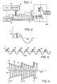
- FIG. 1 illustrates a preferred embodiment of the invention in a simplified block diagram format.
- a corona discharge chamber or reactor 2 is formed from a hollow dielectric cylinder 4 with a wire mesh or solid electrode 6 on the outside of the cylinder which may be a solid metal tube, or thin electroplated or evaporated coating, and an conducting wire electrode 8 extending axially through the inside of the reactor.
- the dielectric used for the reactor wall is preferably a low loss tangent material such as a ceramic or glass; silica was used in a demonstration of the invention.
- Corona rings 10 are preferably provided at the ends of the outer electrode 6 to suppress corona in these regions.
- the inner electrode 8 has a diameter that is small enough, preferably on the order of about 50 micrometers, to produce electric fields at its surface high enough to permit corona emission.
- the reactor includes an inlet conduit 12 through which polluted gas is emitted into the interior of the cylinder, and an outlet conduit 14 through which the gas exits after having had its pollutants remediated by a corona discharge treatment.
- the reactor cell forms a capacitor across which an inductor 16 is connected to establish an LC resonant circuit; the opposite ends of inductor 16 are connected respectively to the inner and outer reactor electrodes 8 and 6.
- the resonant circuit is energized by a simple high-voltage pulser which is shown as a high voltage (preferably about 10 kV) power supply 18 connected in series with the resonant circuit and a switch 20, which may be implemented by a vacuum tetrode or other means.
- a control element, illustrated as pulse generator 22 applies time-spaced pulses to close the switch 20, with the switch remaining open between successive pulses. With each pulse current flows into the capacitance of the reactor, charging it to the power supply's voltage level and initiating a corona discharge pulse within the reactor.
- the resonant circuit has a radio frequency (RF) resonant frequency, with the switch closed to supply an energizing pulse during a portion of one half-cycle of the resonant period.
- RF radio frequency
- the switch is open and current flows out of the reactor capacitance and into the inductor 16.
- This oscillation in which a corona discharge is produced during every other half-period, continues until the voltage decays below the threshold for initiating a discharge. Another pulse is then provided from the power supply to reactivate the self-oscillation process.
- the entire energy of the power supply pulse (except for very small circuit losses) is thus utilized in the reactor.
- the energy is cycled back and forth between the reactor and the inductor until corona action ceases, and the residual energy still remains in the circuit when the next energizing pulse is presented to boost it back to corona-producing levels.
- the resonant circuit's natural frequency is preferably on the order of about 1 MHz, with the effective reactor charging time during which the reactor capacitance is charged up typically extending for only about 10-20 nanoseconds; the corona discharge lasts only for this charging period.
- a natural frequency of about 1 MHz is suitable for treating gaseous flow rates on the order of 100 cm 3 /min. (with a corona discharge chamber about one-quarter meter long).
- a higher frequency would generally be desirable for higher gaseous flow rates.
- the system's natural frequency can be increased by making the chamber walls thicker and thereby reducing its capacitance, making the inductor smaller, or both.
- energizing pulses will be applied intermittently, with intervals between pulses that considerably exceed the duration of the pulses themselves.
- One approach is to simply have the pulse generator 22 pulse the switch 20 closed at periodic intervals, such as once every five or ten self-resonant periods of the corona discharge circuit.
- this can result in less than optimum energy efficiency if the circuit still has sufficient residual energy from the previous pulse to continue corona discharges through self-resonance, or in less than complete pollutant destruction if the corona discharges have terminated too long before the next energizing pulse.
- a sensor 24 can be positioned at the output of the reactor to sense the remaining concentration of pollutants, and in response active a control circuit 26 that initiates a pulse from pulse generator 22 to close the switch 20 and thereby provide another energizing pulse.
- a sensor 27 could be used to sense the level of pollutants within the gas stream entering the reactor, with control circuit 26 increasing the frequency of energizing pulses for higher pollutant levels and reducing the energizing pulse frequency for lower levels.
- control circuit 26 When the reactor is used to remediate pollutants from the exhaust of an engine 28, such as in an automobile, the pollutant level will increase during engine acceleration.
- throttle opening can be identified as a signal from the engine control unit 30, the output of which is applied to the control circuit 26 to increase the energizing pulse frequency during accelerations.
- FIG. 2 illustrates the contrast between the reactor circuit's resonant period ⁇ and the period during which a corona discharge occurs plotted against the voltage differential between the two reactor electrodes.
- a corona discharge does not begin until the voltage exceeds the discharge threshold V th , and lasts until the reactor capacitance has been charged.
- This discharge period 32 is indicated by shading in FIG. 2, and as mentioned above is typically about 10-20 nanoseconds, as opposed to a resonant period of perhaps 1 microsecond.
- FIG. 3 illustrates an application in which an energizing pulse is applied to the resonant reactor circuit during every third resonant cycle (varying peak voltage levels are not shown in this drawing).
- An energizing pulse indicated by cross-hatched bar 34, charges the circuit and initiates a self-resonance which produces subsequent corona discharges (indicated by hatched bars 36 and 38). These are followed by another energizing pulse 34' and self-resonant pulses 36' and 38', and so forth.
- FIG. 4 A more realistic depiction of the intermittent energizing pulsing is given in FIG. 4.
- An energizing pulse indicated by arrow 40 charges the voltage envelope 42 of the reactor circuit up to a peak level 44.
- the reactor circuit then self-oscillates, as indicated by oscillating voltage trace 46, along a decaying envelope that reaches a minimum level at 48, immediately prior to the application of the next charging pulse 50.
- a brief corona discharge is produced during each resonant cycle, with the energizing pulses preferably timed to re-energize the circuit shortly before the termination of corona discharges due to the voltage decay.
- the frequency at which the energizing pulses are applied will generally be well less than half the reactor circuit's natural frequency, with each energizing pulse generally having a duration less than 10% of the resonant period.
- the circuit may be driven by a cw rf source impedance matched to the reactor-inductor load, and providing adequate high voltage.
- the frequency, phase and amplitudes of the reactor's voltage and current waveforms each appear to vary during the decaying oscillation.
- the voltage and current are almost ⁇ /2 radians out of phase with each other, yielding mostly reactive (imaginary) power, except for a brief period in the high-amplitude portions of each cycle during which real power is deposited.
- This behavior is believed to be caused by the positioning of the cylindrical electrode outside of the discharge chamber, causing it to form a capacitor in series with the capacitance of the reactor itself.
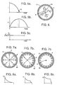
- This phenomenon is illustrated in FIGs. 5a, 5b and 5c.
- the current and voltage waveforms of FIGs. 5a and 5b are generally 90° out of phase with each other except for the charging period, indicated by shaded area 52 in FIG. 5a. During this period the current is slightly retarded in phase and becomes a working current that deposits real power.
- the phase ( ⁇ ) variation during this interval is indicated in FIG. 5c.
- FIG. 6 illustrates a corona discharge within the reactor, with fractal-like streamers 54 building up and extending from the inner electrode 8 to the dielectric cylinder 4 that is surrounded by the outer electrode 6.
- the charging of the dielectric is illustrated in FIGs. 7a, 7b and 7c, with the resulting electrostatic potential across the dielectric illustrated in FIGs. 8a, 8b and 8c.
- real power is deposited into the corona discharge. Once the dielectric has charged the power becomes reactive, and the discharge terminates.
- This process characteristic of capacitively coupled discharges in general, has the beneficial effect of shortening the real power pulse. Short power pulses are important in improving specific energy because the low-energy tail of a long pulse wastes energy in heating the gas. With the self-resonant circuit topology of the invention, short pulses are achieved without complex circuitry or power waste.
- FIGs. 7a-7c illustrate the sequential charging of the reactor dielectric during a discharge
- FIGs. 8a-8c illustrate the corresponding electrostatic potential ⁇ as a function of the reactor's radial coordinate r.
- a high negative electrostatic potential is present on the center electrode 8 relative to the metal outer cylindrical electrode 6.
- the presence of the dielectric 4 prevents arcing, since the corona pulses are typically shorter than arc formation times; the discharge is thus referred to as a silent discharge.
- Electrons 56 move towards the dielectric and begin to charge it; the electrostatic potential at the dielectric is nil prior to this charging.
- the dielectric progressively charges up and its electrostatic potential increases, as illustrated in FIGs. 7b and 8b.
- the discharge terminates when the electrostatic potential on the inner surface of the dielectric approaches that at the inner electrode, at which time the dielectric has a maximum charge, as illustrated in FIGs. 7c and 8c.
- the corona discharge pulse is believed to take the form of a moving wave, charging the adjacent highest field areas of the dielectric first and then sweeping on to the next adjacent uncharged regions, until the charging has progressed all the way around the dielectric.
- the charging sequence typically takes about 10-20 nanoseconds. This type of geometry has important practical advantages in that it provides a reliable mechanical support for the inner electrode, and the dielectric mass also serves as a heat sink for the electrode.
- An uninsulated wire has been found to work best as the inner electrode, although other configurations might also be used.
- a thin elongate blade that extended into the reactor through a wall of the corona chamber did not work as well, since it added to the overall capacitance and required more energy to charge while at the same time reducing the field concentration and thus requiring higher voltage.
- the inner electrode wire should be smooth so as to avoid localized discharge sites that interfere with the desired uniform discharge along the length of the electrode.
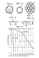
- FIG. 10 An alternate reactor geometry is illustrated in FIG. 10, in which the discharge chamber 60 has a regular polygon cross-section, in this case a hexagon.
- the inner electrode 62 is securely held in place by bonding along the chamber's lower vertex 64.
- An array of such hexagonal reactors 60 is shown in FIG. 11, with the reactors closely packed adjacent each other and oriented to support parallel gas flows. This results in a strong mechanical matrix, in which the individual reactors each require a lower charging voltage than would be required by a single large reactor with the same overall gas flow cross-sectional area.
- the inductor is preferably implemented with a single coil of wire 66 that can extend around the overall array for compactness.
- FIG. 1 is a simple resonant circuit with a single capacitance connected in a loop with the inductor.
- FIG. 12 shows a ringing circuit in which a pair of corona reactors, illustrated as capacitive elements 68a and 68b, are connected in series on opposite sides of an inductor 70.
- FIG. 13 three reactors 72a, 72b, 72c are shown connected in parallel with an inductor 74; additional reactors could be provided as desired.
- the invention has been demonstrated with a corona reactor through which premixed gases were flowed that contained representative pollutants in air, with concentrations varying from about 100 ppm to over 1,000 ppm.
- the tested pollutants included benzene, toluene, xylene, butane, propane, perchloroethylene, trichloroethylene, acetone, NO 2 , NO and exhaust from a portable four-strike generator.
- an increasing destruction of the pollutant was observed with increasing reactor power, until the parent line of the pollutant disappeared below the instrumentation detection threshold.
- the destruction of pollutants occurred without any evidence of the formation of nitrogen oxides; we have also shown the destruction of NO x introduced into the corona reactor.
- the reactor chamber was a silica cylinder 254 mm long, 2 mm thick with a 22 mm internal diameter. It exhibited a 7 pF capacitance, and was connected in circuit with a 16 microHenry inductor.
- the inner electrode wire diameter was 50-130 micrometers, and the gas flow rate was 50 cm 2 /min, with a 4 kV power supply furnishing an energy of 25 micro-Joules per pulse.
- FIG. 14 shows the destruction of toluene and benzene in the corona reactor; more than three orders of magnitude (99.9%) of (DRE) was achieved. Comparable results were obtained for the other tested compounds, with energy requirements increasing with flow rate and pollutant concentration. Benzene was found to require the largest energy input of any compound tested, probably as a result of the stability conferred by its aromatic ring structure.
- catalytic converters In the control of pollutant exhausts from automobile engines and the like, presently available catalytic converters have approached their performance limits of 85-90% DRE; they are deficient in that they allow large quantities of volatile organic compounds (VOCs) into the exhaust both during cold starting and when the driver uses extra acceleration. In addition, typical catalytic converters impress a large back pressure on the engine, driving the engine into a more dirty operating regime and consuming significant power to force the exhaust gases through the converter.
- VOCs volatile organic compounds
- corona reactor as taught by the present invention could substitute for the conventional catalytic converter and achieve a better DRE for both VOCs and NO x , and also eliminate much of the power required to force the exhaust gases through present converters.
- a power level of about 2.6 brake horsepower (bhp) required to force exhaust gases through the catalytic converter of a mid-size car under cruise conditions it is expected that the present corona reactor would require about 1.3 bhp to remediate the engine exhaust at peak power.
- the new corona reactor circuit can be throttled, i.e., its power can be adjusted in real time to provide extra destructive power (by increasing the repetition rate and/or magnitude of the energizing pulses) during hard acceleration or other pollutant-generating activities, and throttled down during cruising to improve fuel economy. It could even receive signals from an intelligent highway to increase pollutant destruction upon entering designated high smog cities, and by providing sensors in the exhaust gas stream the system could be made closed-loop by increasing the energizing pulse rate when an increase in pollutant level is sensed.
- the new corona reactor operating at 13 J/liter would cost about $55 per month, assuming electricity costs of 10 cents per kilowatt hour.
- the treatment process would need to be followed by an aqueous scrubber if halogenated solvents are used.
- Gaseous destruction is also important for closed or semi-closed areas in which the air is recirculated.
- Much of the surface area of floors, walls and ceilings in modern buildings is covered with plastics that outgas plasticizers and other compounds continuously.
- Toxic levels of these VOCs can accumulate in buildings which have insufficient fresh air circulation, adversely affecting sensitive individuals.
- Cars can suffer from the exhaust of other vehicles on the road, and in airplanes the recirculated air exposes the passengers to each other's air borne viruses. All of these problems should be amenable to treatment by the invention, which should oxidize viruses and bacteria down to carbon dioxide and water.
- a second corona reactor in accordance with the invention could be powered from the same power supply.
- a pollutant destruction system connects a capacitive corona discharge chamber 2; 60; 68a, 68b; 72a, 72b, 72c in a self-resonant circuit with an inductive element 16; 66; 70; 74.
- Intermittent energizing signals 34, 34', 40, 50 are furnished from a power supply 18, 20, 22 to induce corona discharges 54 within the chamber, with the resonant circuit responding to the energizing signals by initiating additional corona discharges between energizing signals 34, 34', 40, 50 in a highly energy efficient operation.
- One or more discharge chambers 2; 60; 68a, 68b; 72a, 72b, 72c can be provided in the resonant circuit, with each discharge chamber comprising a dielectric enclosure 4 with a distributed electrode 6; 66 outside and an elongate electrode 8; 58; 62 inside the enclosure.
- the inner electrode 8; 58; 62 can extend either along the chamber axis, or along the inner chamber wall for better support and heat dissipation.
- the energizing pulse frequency can be controlled in various ways, such as in response to a termination of corona discharges 54, an increase in the pollutant concentration or an acceleration of an engine 28 whose exhaust is being treated, or the pulses can be applied at a fixed rate.
Landscapes
- Chemical & Material Sciences (AREA)
- Engineering & Computer Science (AREA)
- Chemical Kinetics & Catalysis (AREA)
- Health & Medical Sciences (AREA)
- General Chemical & Material Sciences (AREA)
- Toxicology (AREA)
- Combustion & Propulsion (AREA)
- Oil, Petroleum & Natural Gas (AREA)
- Analytical Chemistry (AREA)
- Plasma & Fusion (AREA)
- Physics & Mathematics (AREA)
- Environmental & Geological Engineering (AREA)
- Biomedical Technology (AREA)
- Organic Chemistry (AREA)
- General Health & Medical Sciences (AREA)
- General Engineering & Computer Science (AREA)
- Mechanical Engineering (AREA)
- Treating Waste Gases (AREA)
- Exhaust Gas After Treatment (AREA)
- Physical Or Chemical Processes And Apparatus (AREA)
- Electrostatic Separation (AREA)
Claims (10)
- Schadstoffvernichtungssystem mit:einer kapazitiven Corona-Entladungskammer (2; 60; 68a, 68b; 72a, 72b, 72c), die eine innere (8; 58; 62) und eine äußere (6) Elektrode, die einen Kondensator bilden, und einen Strömungspfad (12, 4, 16) für ein schadstoffenthaltendes Fluid aufweist und erregbar ist, um eine schadstoffunschädlichmachende Corona-Entladung (54) zu erzeugen, gekennzeichnet durchein induktives Element (16; 66; 70; 74), das mit den Elektroden (6, 8) der Entladungskammer (2; 60; 68a, 68b; 72a, 72b, 72c) elektrisch gekoppelt ist, um einen Schwingkreis einzurichten, undeine Leistungsversorgung (18, 20, 22), die angeschlossen ist, um dem Schwingkreis intermittierende Erregungssignale (34, 34', 40, 50) zuzuführen, um Corona-Entladungen (54) mittels der Kammer (2; 60; 68a, 68b; 72a, 72b, 72c) zu induzieren, wobei der Schwingkreis auf die Erregungssignale (34, 34', 40, 50) anspricht, indem zusätzliche Corona-Entladungen (36, 38, 36', 38', 46) mittels der Entladungskammer (2; 60; 68a, 68b; 72a, 72b, 72c) zwischen den Erregungssignalen (34, 34', 40, 50) initiiert werden.
- System nach Anspruch 1, dadurch gekennzeichnet, daß der Schwingkreis eine Resonanzfrequenz (1/τ) aufweist und daß die Leistungsversorgung (18, 20, 22) die Erregungssignale (34, 34', 40, 50) mit einer Frequenz zuführt, die kleiner ist als die halbe Resonanzfrequenz (1/τ).
- System nach Anspruch 1 oder 2, dadurch gekennzeichnet, daß die Entladungskammer (2; 60) eine dielektrische Umhüllung (4) aufweist, wobei eine verteilte Elektrode (16; 66; 70; 74) außerhalb der Umhüllung (4) und eine längliche Elektrode (8; 58; 62) innerhalb der Umhüllung (4) vorgesehen sind.
- System nach Anspruch 3, dadurch gekennzeichnet, daß die Entladungskammer (2; 60) eine Innenwand aufweist und daß sich die längliche Elektrode (58; 62) entlang der Innenwand erstreckt.
- System nach einem der Ansprüche 1 - 4, dadurch gekennzeichnet, daß der Schwingkreis eine Resonanzperiode (τ) aufweist und daß die Erregungssignale (34, 34', 40, 50), die von der Leistungsversorgung (18, 20, 22) bereitgestellt werden, Zeitdauern (32) von weniger als 10% der Resonanzperiode (τ) aufweisen.
- Schadstoffvernichtungsverfahren, gekennzeichnet durch:Anlegen eines Erregungssignals (34, 40), um eine Corona-Entladung (54) mittels einer kapazitiven, schadstoffunschädlichmachenden Corona-Entladungskammer (2; 60, 68a, 68b; 72a, 72b, 72c) einzuleiten, die eine innere (8; 58; 62) und eine äußere (6) Elektrode aufweist, die einen Kondensator bilden, der elektrisch mit einem induktiven Element (16; 66; 70; 74) verbunden ist, um einen Eigenschwingkreis einzurichten und um eine Selbstoszillation mittels der Schaltung zu initiieren,Beenden des Erregungssignals (34, 40) undZulassen, daß der Kreis von selbst oszilliert und zusätzliche Corona-Entladungen als Ergebnis der Selbstoszillation erzeugt.
- Verfahren nach Anspruch 6, gekennzeichnet durch den Schritt, an die Entladungskammer (2; 60; 68a, 68b; 72a, 72b, 72c) zusätzliche Erregungssignale (34', 50) anzulegen, wobei die Erregungssignale (34, 34', 40, 50) zeitlich wechselseitig um wenigstens eine selbstoszillierende Corona-Entladung beabstandet sind.
- Verfahren nach Anspruch 7, dadurch gekennzeichnet, daß die Entladungskammer (2; 60; 68a, 68b; 72a, 72b, 72c) dazu angeordnet ist, das Abgas von einer Maschine (28) zu empfangen, und daß das Anlegen der zusätzlichen Erregungssignale (34', 50) gemäß Beschleunigungsvorgängen der Maschine (28) variiert wird.
- Verfahren nach Anspruch 7 oder 8, gekennzeichnet durch den Schritt, die Schadstoffe in einem Fluid zu sensieren (24), das durch die Entladungskammer (2; 60; 68a, 68b; 72a, 72b, 72c) strömt, wobei das Anlegen der Erregungssignale (34, 34', 40, 50) gemäß den sensierten Schadstoffen variiert wird.
- Verfahren nach Anspruch 7 oder 8, mit den weiteren Schritten, das Ende der Corona-Entladungen (54) mittels der Entladungskammer (2; 60; 68a, 68b; 72a, 72b, 72c) zu sensieren und die zusätzlichen Erregungssignale (34', 50) in Antwort auf ein sensiertes Ende von Corona-Entladungen (54) anzulegen.
Applications Claiming Priority (2)
| Application Number | Priority Date | Filing Date | Title |
|---|---|---|---|
| US08/450,449 US5695619A (en) | 1995-05-25 | 1995-05-25 | Gaseous pollutant destruction method using self-resonant corona discharge |
| US450449 | 1995-05-25 |
Publications (3)
| Publication Number | Publication Date |
|---|---|
| EP0744802A2 EP0744802A2 (de) | 1996-11-27 |
| EP0744802A3 EP0744802A3 (de) | 1997-11-26 |
| EP0744802B1 true EP0744802B1 (de) | 2000-10-04 |
Family
ID=23788142
Family Applications (1)
| Application Number | Title | Priority Date | Filing Date |
|---|---|---|---|
| EP96107903A Expired - Lifetime EP0744802B1 (de) | 1995-05-25 | 1996-05-17 | Vorrichtung und Verfahren zum Zerstören von gasförmigen Schadstoffen mit einer eigenresonanten Koronaentladung |
Country Status (5)
| Country | Link |
|---|---|
| US (3) | US5695619A (de) |
| EP (1) | EP0744802B1 (de) |
| JP (1) | JP2702105B2 (de) |
| KR (1) | KR960043397A (de) |
| DE (1) | DE69610523T2 (de) |
Families Citing this family (71)
| Publication number | Priority date | Publication date | Assignee | Title |
|---|---|---|---|---|
| US5806305A (en) | 1994-05-18 | 1998-09-15 | Lockheed Martin Corporation | Method and apparatus for reducing pollutants |
| EP0801809A2 (de) | 1995-06-19 | 1997-10-22 | The University Of Tennessee Research Corporation | Entladungsverfahren sowie elektroden zur erzeugung von plasma unter atmosphärendruck und materialen, die mit diesem verfahren behandelt werden |
| US5863413A (en) | 1996-06-28 | 1999-01-26 | Litex, Inc. | Method for using hydroxyl radical to reduce pollutants in the exhaust gases from the combustion of a fuel |
| FR2751565B1 (fr) * | 1996-07-26 | 1998-09-04 | Air Liquide | Procede et installation de traitement de gaz perfluores et hydrofluorocarbones en vue de leur destruction |
| US6038853A (en) * | 1996-08-19 | 2000-03-21 | The Regents Of The University Of California | Plasma-assisted catalytic storage reduction system |
| US5866081A (en) * | 1996-08-19 | 1999-02-02 | Hughes Electronics Corporation | Deposited inner electrode for corona discharge pollutant destruction reactor |
| US5904905A (en) * | 1996-08-19 | 1999-05-18 | Hughes Electronics Corporation | Corona discharge pollutant destruction apparatus and manufacture method |
| US5753087A (en) * | 1996-08-19 | 1998-05-19 | Hughes Electronics | Multi-electrode corona discharge pollutant destruction apparatus and method |
| US5822981A (en) * | 1996-08-19 | 1998-10-20 | Hughes Electronics Corporation | Automatic control system and method for corona discharge pollutant destruction apparatus |
| US6029442A (en) | 1996-12-18 | 2000-02-29 | Litex, Inc. | Method and apparatus for using free radicals to reduce pollutants in the exhaust gases from the combustion of fuel |
| US6321531B1 (en) | 1996-12-18 | 2001-11-27 | Litex, Inc. | Method and apparatus for using free radicals to reduce pollutants in the exhaust gases from the combustion of a fuel |
| US6047543A (en) | 1996-12-18 | 2000-04-11 | Litex, Inc. | Method and apparatus for enhancing the rate and efficiency of gas phase reactions |
| US6475350B2 (en) * | 1997-07-18 | 2002-11-05 | Noxtech Inc | Method for removing NOx and other pollutants from gas streams using a plasma assisted catalyst |
| GB9715409D0 (en) * | 1997-07-23 | 1997-09-24 | Aea Technology Plc | Gas purification |
| NO310394B1 (no) * | 1997-09-18 | 2001-07-02 | Applied Plasma Physics As | Fremgangsmåte for å regulere mengden av ioniserte gasser og/eller partikler over veier, gater, plasser eller lignende |
| US6264898B1 (en) | 1997-11-19 | 2001-07-24 | The Titan Corporation | Pulsed corona discharge apparatus |
| JP2001523551A (ja) * | 1997-11-19 | 2001-11-27 | マックスウェル テクノロジーズ システムズ ディビジョン、インコーポレイテッド | 半径設計のパルス状コロナ放電装置 |
| US6156162A (en) * | 1998-03-02 | 2000-12-05 | Low Emissions Technologies Research And Development Partnership | Power supply for dielectric barrier discharge plasma |
| US6461870B2 (en) * | 1998-05-06 | 2002-10-08 | Isotechnika Inc. | 13C glucose breath test for the diagnosis of diabetic indications and monitoring glycemic control |
| DE19823748C2 (de) * | 1998-05-27 | 2000-05-18 | Siemens Ag | Verfahren und Vorrichtung zur plasmachemischen Erzeugung von Stickstoffmonoxid |
| BR9911882A (pt) | 1998-07-13 | 2005-02-15 | Univ Texas | Processo de tratamento de câncer empregando anticorpos a aminofosfolipìdios |
| GB9819416D0 (en) * | 1998-09-07 | 1998-10-28 | Aea Technology Plc | Treatment of aircraft cabin air |
| GB2346528A (en) * | 1999-01-21 | 2000-08-09 | Aea Technology Plc | Power supply for processing of gaseous media |
| GB9903400D0 (en) * | 1999-02-16 | 1999-04-07 | Aea Technology Plc | Reactor for plasma assisted gas processing |
| US6146599A (en) | 1999-02-24 | 2000-11-14 | Seagate Technology Llc | Dielectric barrier discharge system and method for decomposing hazardous compounds in fluids |
| US6455014B1 (en) * | 1999-05-14 | 2002-09-24 | Mesosystems Technology, Inc. | Decontamination of fluids or objects contaminated with chemical or biological agents using a distributed plasma reactor |
| KR100348408B1 (ko) * | 1999-08-05 | 2002-08-10 | 주식회사제4기한국 | 플라즈마를 이용한 유해가스 분해장치 |
| JP2001087620A (ja) * | 1999-09-27 | 2001-04-03 | Ngk Insulators Ltd | 物質処理方法および装置 |
| US7192553B2 (en) | 1999-12-15 | 2007-03-20 | Plasmasol Corporation | In situ sterilization and decontamination system using a non-thermal plasma discharge |
| US7029636B2 (en) | 1999-12-15 | 2006-04-18 | Plasmasol Corporation | Electrode discharge, non-thermal plasma device (reactor) for the pre-treatment of combustion air |
| US6955794B2 (en) * | 1999-12-15 | 2005-10-18 | Plasmasol Corporation | Slot discharge non-thermal plasma apparatus and process for promoting chemical reaction |
| US7094322B1 (en) | 1999-12-15 | 2006-08-22 | Plasmasol Corporation Wall Township | Use of self-sustained atmospheric pressure plasma for the scattering and absorption of electromagnetic radiation |
| US6923890B2 (en) * | 1999-12-15 | 2005-08-02 | Plasmasol Corporation | Chemical processing using non-thermal discharge plasma |
| US6451252B1 (en) | 2000-01-20 | 2002-09-17 | Regents Of The University Of Minnesota | Odor removal system and method having ozone and non-thermal plasma treatment |
| US6345497B1 (en) * | 2000-03-02 | 2002-02-12 | The Regents Of The University Of California | NOx reduction by electron beam-produced nitrogen atom injection |
| US6363714B1 (en) | 2000-06-09 | 2002-04-02 | Ford Global Technologies, Inc. | Plasma-catalyst control system |
| US6432280B1 (en) * | 2000-10-23 | 2002-08-13 | Pioneer Industrial Technologies, Inc. | Pollution control device |
| US6911225B2 (en) * | 2001-05-07 | 2005-06-28 | Regents Of The University Of Minnesota | Method and apparatus for non-thermal pasteurization of living-mammal-instillable liquids |
| US7011790B2 (en) * | 2001-05-07 | 2006-03-14 | Regents Of The University Of Minnesota | Non-thermal disinfection of biological fluids using non-thermal plasma |
| US6562386B2 (en) | 2001-05-07 | 2003-05-13 | Regents Of The University Of Minnesota | Method and apparatus for non-thermal pasteurization |
| US7078000B2 (en) * | 2001-06-14 | 2006-07-18 | Delphi Technologies, Inc. | Apparatus and method for mat protection of non-thermal plasma reactor |
| US6893617B2 (en) * | 2001-06-14 | 2005-05-17 | Delphi Technologies, Inc. | Apparatus and method for retention of non-thermal plasma reactor |
| JP2004535041A (ja) | 2001-07-02 | 2004-11-18 | プラズマゾル・コーポレイション | 大気圧プラズマ照射装置用の新規な電極及びその使用方法 |
| JP2005519729A (ja) * | 2001-08-02 | 2005-07-07 | プラズマゾル・コーポレイション | 非熱放電プラズマによる化学プロセッシング |
| AU2003237780A1 (en) * | 2002-02-19 | 2003-09-29 | Plasmasol Corporation | Slot discharge non-thermal plasma apparatus and process for promoting chemical reaction |
| US20060039844A1 (en) * | 2002-03-25 | 2006-02-23 | The Board Of Trustees Of The University Of Illinois | Method for abatement of voc in exhaust gases by wet pulse corona discharge |
| US6604356B1 (en) * | 2002-04-19 | 2003-08-12 | Envirolift, Llc | Emission control system for generator engine |
| US6840034B2 (en) * | 2002-04-19 | 2005-01-11 | Envirolift, Llc | Emission control apparatus for marine generator engine |
| US20040000475A1 (en) * | 2002-06-27 | 2004-01-01 | Cho Byong Kwon | Plasma reactor having regions of active and passive electric field |
| US7329290B2 (en) * | 2002-10-08 | 2008-02-12 | Hrl Laboratories, Llc | Fuel reforming apparatus for producing a carbon-monoxide free reformed fuel gas comprising hydrogen |
| US6959538B2 (en) * | 2002-12-06 | 2005-11-01 | General Motors Corporation | Ultra low power plasma reactor system for automotive NOx emission control |
| US7029637B2 (en) | 2003-01-09 | 2006-04-18 | H203, Inc. | Apparatus for ozone production, employing line and grooved electrodes |
| US6991768B2 (en) * | 2003-07-28 | 2006-01-31 | Iono2X Engineering L.L.C. | Apparatus and method for the treatment of odor and volatile organic compound contaminants in air emissions |
| US7767167B2 (en) * | 2003-07-28 | 2010-08-03 | Iono2X Engineering, L.L.C. | Dielectric barrier discharge cell with hermetically sealed electrodes, apparatus and method for the treatment of odor and volatile organic compound contaminants in air emissions, and for purifying gases and sterilizing surfaces |
| US8475723B2 (en) * | 2003-07-28 | 2013-07-02 | Iono2X Engineering, L.L.C. | Dielectric barrier discharge cell with hermetically sealed electrodes and automatic washing of electrodes during operation of the cell |
| US7377101B2 (en) * | 2004-02-13 | 2008-05-27 | Fleetguard, Inc. | Plasma fuel converter NOx adsorber system for exhaust aftertreatment |
| US6957528B1 (en) * | 2004-06-09 | 2005-10-25 | General Motors Corporation | No reduction with diesel fuel reformed by nonthermal hyperplasma |
| JP2006101480A (ja) * | 2004-07-12 | 2006-04-13 | Applied Materials Inc | プラズマチャンバーとともに使用する固定インピーダンス変換回路網用の装置および方法 |
| US8105546B2 (en) * | 2005-05-14 | 2012-01-31 | Air Phaser Environmental Ltd. | Apparatus and method for destroying volatile organic compounds and/or halogenic volatile organic compounds that may be odorous and/or organic particulate contaminants in commercial and industrial air and/or gas emissions |
| WO2007068085A1 (en) * | 2005-12-12 | 2007-06-21 | Albonia Innovative Technologies Ltd. | Method and apparatus for treating contaminated material |
| US7628927B2 (en) * | 2005-12-14 | 2009-12-08 | Vesitech, Inc. | Reactor for removing chemical and biological contaminants from a contaminated fluid |
| US7931811B2 (en) * | 2006-10-27 | 2011-04-26 | Regents Of The University Of Minnesota | Dielectric barrier reactor having concentrated electric field |
| WO2009091273A1 (en) * | 2008-01-18 | 2009-07-23 | Nandor Burany | Corona discharge treater with resonant voltage multiplication |
| WO2012127896A1 (ja) * | 2011-03-22 | 2012-09-27 | 日本碍子株式会社 | パルス発生装置及びパルス発生装置の設置方法 |
| DK3003988T3 (da) * | 2013-06-07 | 2020-02-03 | Leibniz Institut Fuer Plasmaforschung Und Tech E V | Anordning til at behandle fluider ved at producere koronaudladninger i en fluidvolumen |
| US9574586B2 (en) * | 2015-04-27 | 2017-02-21 | The Boeing Company | System and method for an electrostatic bypass |
| WO2018089577A1 (en) * | 2016-11-10 | 2018-05-17 | EP Technologies LLC | Methods and systems for generating plasma activated liquid |
| CN111433549A (zh) | 2017-07-17 | 2020-07-17 | 分形散热器技术有限责任公司 | 多重分形散热器系统及方法 |
| KR102024586B1 (ko) * | 2017-10-30 | 2019-09-24 | (주)수도프리미엄엔지니어링 | 펄스 제어를 이용한 플라즈마 발생용 전압 공급장치 |
| FR3090409B1 (fr) * | 2018-12-21 | 2023-04-14 | Paris Sciences Lettres Quartier Latin | Reacteur pour la conversion du dioxyde de carbone |
| US11890398B2 (en) * | 2022-02-17 | 2024-02-06 | Mikhail Aleksandrovich Meshchaninov | Air cleaning device |
Family Cites Families (8)
| Publication number | Priority date | Publication date | Assignee | Title |
|---|---|---|---|---|
| US3205162A (en) * | 1961-08-08 | 1965-09-07 | Celanese Corp | Electric discharge process and apparatus |
| US4657738A (en) * | 1984-04-30 | 1987-04-14 | Westinghouse Electric Corp. | Stack gas emissions control system |
| US4695358A (en) * | 1985-11-08 | 1987-09-22 | Florida State University | Method of removing SO2, NOX and particles from gas mixtures using streamer corona |
| CH676844A5 (de) * | 1988-09-09 | 1991-03-15 | Asea Brown Boveri | |
| US5284556A (en) * | 1991-05-01 | 1994-02-08 | Plasmachines, Inc. | Exhaust treatment system and method |
| DE4235766C2 (de) * | 1992-10-24 | 1998-11-12 | Agrodyn Hochspannungstechnik G | Koronagenerator |
| US5490973A (en) * | 1994-05-23 | 1996-02-13 | The United States Of America As Represented By The Secretary Of The Navy | Pulsed corona reactor system for abatement of pollution by hazardous agents |
| US5549795A (en) * | 1994-08-25 | 1996-08-27 | Hughes Aircraft Company | Corona source for producing corona discharge and fluid waste treatment with corona discharge |
-
1995
- 1995-05-25 US US08/450,449 patent/US5695619A/en not_active Expired - Fee Related
-
1996
- 1996-05-17 EP EP96107903A patent/EP0744802B1/de not_active Expired - Lifetime
- 1996-05-17 DE DE69610523T patent/DE69610523T2/de not_active Expired - Fee Related
- 1996-05-25 KR KR1019960017892A patent/KR960043397A/ko not_active Abandoned
- 1996-05-27 JP JP8132358A patent/JP2702105B2/ja not_active Expired - Lifetime
-
1997
- 1997-05-30 US US08/866,353 patent/US5855855A/en not_active Expired - Fee Related
- 1997-05-30 US US08/866,871 patent/US5843383A/en not_active Expired - Fee Related
Also Published As
| Publication number | Publication date |
|---|---|
| EP0744802A3 (de) | 1997-11-26 |
| US5843383A (en) | 1998-12-01 |
| DE69610523T2 (de) | 2001-05-17 |
| JP2702105B2 (ja) | 1998-01-21 |
| JPH0999211A (ja) | 1997-04-15 |
| KR960043397A (ko) | 1996-12-23 |
| EP0744802A2 (de) | 1996-11-27 |
| US5695619A (en) | 1997-12-09 |
| US5855855A (en) | 1999-01-05 |
| DE69610523D1 (de) | 2000-11-09 |
Similar Documents
| Publication | Publication Date | Title |
|---|---|---|
| EP0744802B1 (de) | Vorrichtung und Verfahren zum Zerstören von gasförmigen Schadstoffen mit einer eigenresonanten Koronaentladung | |
| US6224653B1 (en) | Electrostatic method and means for removing contaminants from gases | |
| US5433832A (en) | Exhaust treatment system and method | |
| US5827407A (en) | Indoor air pollutant destruction apparatus and method using corona discharge | |
| US5927069A (en) | Multi-electrode corona discharge pollutant destruction apparatus | |
| KR100239598B1 (ko) | 다단계 가스 오염물 제거 장치 및 방법 | |
| KR100273993B1 (ko) | 코로나 방전 오염 물질 분해 장치에서의 NOx의 처리를 위한 연료 주입 시스템 및 방법 | |
| US6906280B2 (en) | Fast pulse nonthermal plasma reactor | |
| US5866081A (en) | Deposited inner electrode for corona discharge pollutant destruction reactor | |
| EP0824952B1 (de) | Verfahren zur Verminderung von NOx in einer Vorrichtung zum Zerstören von Schadstoffen mit einer Koronaentladung | |
| US7559976B2 (en) | Multi-stage collector for multi-pollutant control | |
| US20060193759A1 (en) | Nonthermal plasma processor utilizing additive-gas injection and/or gas extraction | |
| US20030170154A1 (en) | Plasma assisted catalytic treatment of gases | |
| US6156162A (en) | Power supply for dielectric barrier discharge plasma | |
| Brandenburg et al. | Plasma-based depollution of exhausts: principles, state of the art and future prospects | |
| Rueda | Reduction of nitrogen oxides in diesel exhaust using dielectric barrier discharges driven by current-mode power supplies | |
| JP2003275541A (ja) | プラズマ装置およびその制御方法 | |
| KR200253453Y1 (ko) | 캐스캐이딩 방식을 적용한 고전압 펄스발생장치 | |
| WO2005115610A1 (en) | Fast pulse nonthermal plasma reactor | |
| Penetrante et al. | Application of non-thermal plasmas to pollution control | |
| Kelly et al. | Reducing soot emissions from diesel engines using One atmosphere uniform Glow Discharge Plasma |
Legal Events
| Date | Code | Title | Description |
|---|---|---|---|
| PUAI | Public reference made under article 153(3) epc to a published international application that has entered the european phase |
Free format text: ORIGINAL CODE: 0009012 |
|
| AK | Designated contracting states |
Kind code of ref document: A2 Designated state(s): DE FR GB |
|
| PUAL | Search report despatched |
Free format text: ORIGINAL CODE: 0009013 |
|
| AK | Designated contracting states |
Kind code of ref document: A3 Designated state(s): DE FR GB |
|
| 17P | Request for examination filed |
Effective date: 19980416 |
|
| RAP1 | Party data changed (applicant data changed or rights of an application transferred) |
Owner name: HUGHES ELECTRONICS CORPORATION |
|
| 17Q | First examination report despatched |
Effective date: 19990401 |
|
| GRAG | Despatch of communication of intention to grant |
Free format text: ORIGINAL CODE: EPIDOS AGRA |
|
| 17Q | First examination report despatched |
Effective date: 19990401 |
|
| GRAG | Despatch of communication of intention to grant |
Free format text: ORIGINAL CODE: EPIDOS AGRA |
|
| GRAH | Despatch of communication of intention to grant a patent |
Free format text: ORIGINAL CODE: EPIDOS IGRA |
|
| GRAH | Despatch of communication of intention to grant a patent |
Free format text: ORIGINAL CODE: EPIDOS IGRA |
|
| GRAA | (expected) grant |
Free format text: ORIGINAL CODE: 0009210 |
|
| AK | Designated contracting states |
Kind code of ref document: B1 Designated state(s): DE FR GB |
|
| REF | Corresponds to: |
Ref document number: 69610523 Country of ref document: DE Date of ref document: 20001109 |
|
| ET | Fr: translation filed | ||
| PLBE | No opposition filed within time limit |
Free format text: ORIGINAL CODE: 0009261 |
|
| STAA | Information on the status of an ep patent application or granted ep patent |
Free format text: STATUS: NO OPPOSITION FILED WITHIN TIME LIMIT |
|
| RAP2 | Party data changed (patent owner data changed or rights of a patent transferred) |
Owner name: RAYTHEON COMPANY |
|
| 26N | No opposition filed | ||
| REG | Reference to a national code |
Ref country code: GB Ref legal event code: IF02 |
|
| REG | Reference to a national code |
Ref country code: GB Ref legal event code: 732E |
|
| PGFP | Annual fee paid to national office [announced via postgrant information from national office to epo] |
Ref country code: FR Payment date: 20040408 Year of fee payment: 9 |
|
| PGFP | Annual fee paid to national office [announced via postgrant information from national office to epo] |
Ref country code: GB Payment date: 20040415 Year of fee payment: 9 |
|
| PGFP | Annual fee paid to national office [announced via postgrant information from national office to epo] |
Ref country code: DE Payment date: 20040422 Year of fee payment: 9 |
|
| PG25 | Lapsed in a contracting state [announced via postgrant information from national office to epo] |
Ref country code: GB Free format text: LAPSE BECAUSE OF NON-PAYMENT OF DUE FEES Effective date: 20050517 |
|
| PG25 | Lapsed in a contracting state [announced via postgrant information from national office to epo] |
Ref country code: DE Free format text: LAPSE BECAUSE OF NON-PAYMENT OF DUE FEES Effective date: 20051201 |
|
| GBPC | Gb: european patent ceased through non-payment of renewal fee |
Effective date: 20050517 |
|
| PG25 | Lapsed in a contracting state [announced via postgrant information from national office to epo] |
Ref country code: FR Free format text: LAPSE BECAUSE OF NON-PAYMENT OF DUE FEES Effective date: 20060131 |
|
| REG | Reference to a national code |
Ref country code: FR Ref legal event code: ST Effective date: 20060131 |