EP0744544A1 - Dichtstreifen für eine Schubdüse - Google Patents
Dichtstreifen für eine Schubdüse Download PDFInfo
- Publication number
- EP0744544A1 EP0744544A1 EP96303377A EP96303377A EP0744544A1 EP 0744544 A1 EP0744544 A1 EP 0744544A1 EP 96303377 A EP96303377 A EP 96303377A EP 96303377 A EP96303377 A EP 96303377A EP 0744544 A1 EP0744544 A1 EP 0744544A1
- Authority
- EP
- European Patent Office
- Prior art keywords
- divergent
- flap
- flaps
- nozzle
- face
- Prior art date
- Legal status (The legal status is an assumption and is not a legal conclusion. Google has not performed a legal analysis and makes no representation as to the accuracy of the status listed.)
- Granted
Links
- 239000007789 gas Substances 0.000 claims description 14
- 235000020637 scallop Nutrition 0.000 claims description 6
- 125000006850 spacer group Chemical group 0.000 claims description 5
- 230000013011 mating Effects 0.000 claims description 4
- 241000237509 Patinopecten sp. Species 0.000 claims description 2
- 230000003247 decreasing effect Effects 0.000 claims description 2
- 241000237503 Pectinidae Species 0.000 description 4
- 230000007423 decrease Effects 0.000 description 2
- 239000002184 metal Substances 0.000 description 2
- 238000011144 upstream manufacturing Methods 0.000 description 2
- 230000003466 anti-cipated effect Effects 0.000 description 1
- 238000005452 bending Methods 0.000 description 1
- 238000007789 sealing Methods 0.000 description 1
Images



Classifications
-
- F—MECHANICAL ENGINEERING; LIGHTING; HEATING; WEAPONS; BLASTING
- F02—COMBUSTION ENGINES; HOT-GAS OR COMBUSTION-PRODUCT ENGINE PLANTS
- F02K—JET-PROPULSION PLANTS
- F02K1/00—Plants characterised by the form or arrangement of the jet pipe or nozzle; Jet pipes or nozzles peculiar thereto
- F02K1/78—Other construction of jet pipes
- F02K1/80—Couplings or connections
- F02K1/805—Sealing devices therefor, e.g. for movable parts of jet pipes or nozzle flaps
-
- F—MECHANICAL ENGINEERING; LIGHTING; HEATING; WEAPONS; BLASTING
- F05—INDEXING SCHEMES RELATING TO ENGINES OR PUMPS IN VARIOUS SUBCLASSES OF CLASSES F01-F04
- F05D—INDEXING SCHEME FOR ASPECTS RELATING TO NON-POSITIVE-DISPLACEMENT MACHINES OR ENGINES, GAS-TURBINES OR JET-PROPULSION PLANTS
- F05D2250/00—Geometry
- F05D2250/30—Arrangement of components
- F05D2250/32—Arrangement of components according to their shape
- F05D2250/324—Arrangement of components according to their shape divergent
Definitions
- This invention pertains to engine nozzles in general, and to seals for sealing between flaps within the engine nozzle in particular.
- convergent-divergent In certain gas turbine driven aircraft, it is advantageous to equip the engine with a convergent-divergent (c ⁇ d) exhaust nozzle.
- convergent-divergent describes an exhaust nozzle having a convergent section upstream of a divergent section. Exhaust gases exiting the turbine(s) pass through the decreasing diameter convergent section before passing through the increasing diameter divergent section.
- both the convergent and divergent sections are symmetric about the longitudinal axis of the engine.
- the divergent section includes a plurality of flaps, hinged at the interface between the convergent and divergent sections, which can be rotated radially outward to change the angle at which the divergent section diverges from the longitudinal axis. Flap seals are positioned between the flaps of the divergent section to prevent exhaust gas from escaping between the flaps.
- the axis of the divergent section may be skewed from the longitudinal axis to create pitch and yaw thrust vectoring. Skewing the divergent flaps causes the position of the flaps relative to one another to vary depending upon the direction and magnitude of the skew and the position of the particular flap relative to the skew. In some circumferential segments of the skewed nozzle, spacing between flaps decreases and flaps may overlap and mechanically damage one another during vectoring maneuvers. In other segments, spacing between flaps increases and forces the seals to assume a complicated geometry to accommodate what would otherwise have been a circumferential space between adjacent flaps.
- the cross- sectional area of the nozzle may be different than anticipated, and/or inconsistent.
- performance characteristics of the nozzle depend on the ratio of nozzle and throat cross-sectional areas. Inconsistent nozzle cross-sectional area, therefore, is an undesirable attribute.
- a divergent flap seal for a gas turbine engine exhaust nozzle having a longitudinal axis comprising: a body, a spine member, attached to a first side of said body, extending along the length of said body; a flap position guide, positioned on said first side of said body, adjacent an aft end of said body, said flap position guide extending out from said body a distance sufficient, in use, to separate adjacent flaps regardless of the vectored position of the nozzle.
- a divergent flap seal for a gas turbine engine exhaust nozzle having a longitudinal axis having a body, a spine member, and a flap position guide.
- the flap position guide separates adjacent divergent flaps regardless of the angle the flaps are skewed relative to the longitudinal axis, thereby more evenly distributing the flaps about the circumference of the nozzle.
- An advantage of the present invention is that the flap position guide of each flap seal prevents adjacent flaps from overlapping one another. As a result, flaps are prevented from mechanically damaging one another. In addition, separating adjacent flaps distributes the flaps more evenly about the circumference of the nozzle. Even flap distribution helps provide a consistent nozzle cross-sectional area in a vectorable exhaust nozzle, and therefore a more consistently performing exhaust nozzle.
- a further advantage of the present invention is that it helps to maximize the kinematic envelope of the vectorable nozzle. Distributing the flaps more evenly about the circumference of the nozzle reduces the interferences between adjacent flaps and thereby increase the envelope within which the nozzle may diverge.
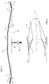
- FIG. 1 shows a partial perspective view of an exhaust nozzle for a gas turbine engine.
- FIG. 2 is a diagrammatic illustration showing an exhaust nozzle.
- FIG. 3 is an hot-side view of a flap seal.
- FIG. 4 is a cold-side view of the flap seal shown in FIG. 3.
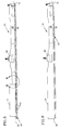
- FIG. 5 is a side view of the flap seal, partially cut-away, showing one embodiment of a flap position guide.
- FIG. 6 is a side view of the flap seal, partially cut-away, showing another embodiment of a flap position guide.
- FIG. 7 is a sectional view of the flap seal shown in FIG. 3.
- FIG. 8 is a sectional view of the flap seal shown in FIG. 3.
- FIG.9 is a diagrammatic partial view of the hot side of the seal showing a particular face segment embodiment.
- FIG. 10 is a diagrammatic partial view of the hot side of the seal showing another face segment embodiment.
- a gas turbine engine includes an exhaust nozzle 10 comprising a convergent section 12 upstream of a divergent section 14. Both the convergent 12 and the divergent 14 sections are symmetrically arranged about the longitudinal axis 16 of the engine, although the divergent section 14 may be selectively skewed from the axis 16.
- FIG.2 shows a diagrammatic representation of a divergent section skewed an angle ⁇ from the longitudinal axis 16 of the engine.
- the divergent section 14 includes a plurality of flaps 18 and flap seals 20 pivotly attached to the convergent section 12 on one end.
- Mechanical linkage 22 links the flaps 18 and the flap seals 20 together, such that actuating the flaps causes the seals to actuate in like manner.
- a second mechanical linkage 24, attached to each of the flaps 18, actuates the flaps 18 and flap seals 20 about the longitudinal axis 16, or about an axis skewed relative to the longitudinal axis 16, or both.
- each flap seal 20 includes a body 26, a spine member 28, a plurality of face segments 30, and a flap position guide 31 (see also FIGS. 5 and 6).
- FIG.3 shows a "hot-side" view of a flap seal 20.
- the hot-side of the flap seal 20 is defined as that side which is directly exposed to exhaust gases exiting the engine.
- the cold-side of the flap seal 20 is defined as the side of the flap seal 20 opposite that which is directly exposed to exhaust gases.
- the body 26 may be described as having a length 32, defined as extending between a forward end 33 and an aft end 35, and a width 34.
- the body 26 further includes a plurality of corrugations 36 formed in the body 26, extending across the body width 34, and a first 38 and a second 40 channel (see FIG.7 also). Corrugation geometries other than that shown in FIGS. 5,6, and 8 may be used alternatively.
- the first 38 and second 40 channel are formed along the width edges 42,44 of the body 26 by folding the edges of the body 26 sheet metal back over into a "U" shape.
- the walls of the "U” extend lengthwise along the body 26.
- a spacer 48 having a predetermined thickness is inserted into each channel 38,40 and spot welded into place.
- each face segment 30 includes a midsection 50, having an inner 52 and an outer 54 surface, a first edge 56, a second edge 58, a first end 60, and a second end 62 (see FIG.9).
- the edges 56,58 are parallel with each other and substantially perpendicular with the ends 60,62.
- Each face segment 30 further includes a first flange 64 and a second flange 66.
- the first flange 64 is attached to the first edge 56 of the midsection 50.
- the second flange 66 is attached to the second edge 58 of the midsection 50.
- the first 64 and second 66 flanges are formed by bending sections of the face segment 30 away from the midsection 50.
- the face segments 30 may be formed from a sheet metal blank.
- the first 64 and second 66 flanges comprise mating geometries such that when face segments 30 are positioned adjacent each other, the first flange 64 of one face segment 30 couples with the second flange 66 of the adjacent face segment 30.
- FIG.8 shows the preferred embodiment of the first 64 and second 66 flanges.
- the first flange 64 is perpendicular to the midsection 50.
- the second flange 66 is "L" shaped; i.e., it includes a first section 68 perpendicular to the midsection 50 and a second section 70 parallel to the midsection 50.
- the end face segment 72 includes only one of the first 64 or second 66 flanges (see FIG.8) and is extended in the midsection 50.
- the end face segment 72 and body 26 When assembled with the body 26, the end face segment 72 and body 26 create a pocket 74 (shown in phantom) for receiving a hinge means 76 for pivotly attaching the seal 20.
- United States Patent No. 5,238,189 hereby incorporated by reference, discloses such a hinge means 76.
- the face segments 30 further comprise a scallop 78 extending along either the first 56 or second 58 edge, or both.
- the scallops 78 decrease the distance between the first 56 and second 58 edges in a particular face segment 30 and increase the distance between edges 56,58 of adjacent face segments 30 to permit greater thermal growth in a particular area of the seal 20.
- the scallops 78 may be placed in the center region of all face segments 30 if the seal 20 is to experience a steep thermal gradient in the center region along the entire length of the seal 20.
- the face segments 30 in that particular area may include scallops 78 to allow for greater thermal expansion in that particular area; i.e., hot spots at one end of the seal 20 or along the width edges 42,44, etc.
- FIG.8 shows scallops 78 near the ends 60,62 of the face segments 30 to allow for thermal expansion near the ends 60,62 and to facilitate translation within the channels 38,40.
- the spine member 28 is a rigid member attached to the cold-side of the body 26, attached by conventional means to the corrugations 36 of the body 26.
- the spine member 28 includes means 80 for attaching the flap seal 20 to the linkage 24 (see FIG.1) which connects the flaps 18 and flap seals 20 together.
- the flap position guide 31 is attached to the spine member 28 at a position between the flap seal attachment means 80 and the aft end 35.
- the flap position guide 31 extends out from the body 26 a distance sufficient to separate adjacent flaps 18 regardless of the vectored position of the nozzle.
- FIG. 6 shows an alternative embodiment of the flap position guide 37, where the guide 31 is integrally formed within the spine member 28 in the region between the flap seal attachment means 80 and the aft end 35 of the seal 20.
- the face segments 30 are attached to the corrugations 36 of the body 26 by spot welds 90 (see FIG. 3 also).
- the face segments 30 are sized and positioned such that the first flange 64 and second flange 66 of adjacent face segments 30 nest together, separated by a predetermined gap 82.
- the gap 82 is sized to allow the expected thermal expansion of adjacent face segments 30.
- the mating geometries of the first 64 and second 66 flanges substantially prevent gases passing along the outer surface 54 of the face segments 30 from passing between the face Segments 30.
- the ends 60,62 of the segments 30 are free to translate within the channels 38,40 (FIG.7).
- the spacers 48 positioned in the channels 38,40, inboard of the ends 60,62, help to maintain a channel gap 84 sufficient to prevent binding of the face segments 30.
- the spacers 48 also help position the face segments 30 during assembly.
- the present invention in its preferred embodiments at least provides a divergent flap seal that prevents mechanical damage between adjacent divergent flaps in a vectorable exhaust nozzle, an exhaust nozzle flap seal that can accommodate complex nozzle geometries in a vectorable exhaust nozzle, and a divergent flap seal that helps provide a consistent nozzle cross-sectional area in a vectorable exhaust nozzle.
Landscapes
- Engineering & Computer Science (AREA)
- Chemical & Material Sciences (AREA)
- Combustion & Propulsion (AREA)
- Mechanical Engineering (AREA)
- General Engineering & Computer Science (AREA)
- Turbine Rotor Nozzle Sealing (AREA)
- Gasket Seals (AREA)
Applications Claiming Priority (2)
| Application Number | Priority Date | Filing Date | Title |
|---|---|---|---|
| US446361 | 1995-05-22 | ||
| US08/446,361 US5683034A (en) | 1995-05-22 | 1995-05-22 | Engine exhaust nozzle seal |
Publications (2)
| Publication Number | Publication Date |
|---|---|
| EP0744544A1 true EP0744544A1 (de) | 1996-11-27 |
| EP0744544B1 EP0744544B1 (de) | 2000-08-23 |
Family
ID=23772299
Family Applications (1)
| Application Number | Title | Priority Date | Filing Date |
|---|---|---|---|
| EP96303377A Expired - Lifetime EP0744544B1 (de) | 1995-05-22 | 1996-05-14 | Dichtstreifen für eine Schubdüse |
Country Status (4)
| Country | Link |
|---|---|
| US (1) | US5683034A (de) |
| EP (1) | EP0744544B1 (de) |
| JP (1) | JP3844809B2 (de) |
| DE (1) | DE69609896T2 (de) |
Cited By (3)
| Publication number | Priority date | Publication date | Assignee | Title |
|---|---|---|---|---|
| EP1211406A1 (de) * | 2000-11-30 | 2002-06-05 | General Electric Company | Verfahren und Vorrichtung für die Abdichtung verstellbarer Düsen in Gasturbinen |
| EP2096291A1 (de) * | 2008-02-29 | 2009-09-02 | General Electric Company | Abgasdüsendichtung mit segmentierter Basisfläche |
| GB2495176A (en) * | 2011-09-30 | 2013-04-03 | United Technologies Corp | A gas turbine engine gas path liner |
Families Citing this family (14)
| Publication number | Priority date | Publication date | Assignee | Title |
|---|---|---|---|---|
| US6745570B2 (en) | 2002-02-01 | 2004-06-08 | General Electric Co. | Methods and apparatus for sealing gas turbine engine nozzles using a flap system |
| US6658854B2 (en) | 2002-02-01 | 2003-12-09 | General Electric Co. | Methods and apparatus for retaining gas turbine engine nozzle basesheets |
| FR2857414B1 (fr) * | 2003-07-08 | 2007-06-08 | Snecma Moteurs | Volet souple de tuyere a section variable de turbomachine |
| FR2860046B1 (fr) * | 2003-09-19 | 2005-12-02 | Snecma Moteurs | Volet chaud commande de tuyere axisymetrique de turboreacteur |
| US7302793B2 (en) * | 2003-10-29 | 2007-12-04 | General Electric Company | Methods and apparatus to reduce turbine engine nozzle basesheet stresses |
| CA2547846A1 (en) * | 2003-12-01 | 2005-11-17 | The University Of Mississippi | Method and device for reducing engine noise |
| US7624567B2 (en) | 2005-09-20 | 2009-12-01 | United Technologies Corporation | Convergent divergent nozzle with interlocking divergent flaps |
| US8205454B2 (en) * | 2007-02-06 | 2012-06-26 | United Technologies Corporation | Convergent divergent nozzle with edge cooled divergent seals |
| US7757477B2 (en) * | 2007-02-20 | 2010-07-20 | United Technologies Corporation | Convergent divergent nozzle with slot cooled nozzle liner |
| US8122722B2 (en) * | 2008-02-29 | 2012-02-28 | General Electric Company | Exhaust nozzle seal with segmented basesheet disposed between side rails |
| US8904752B2 (en) * | 2010-03-12 | 2014-12-09 | Aerojet Rocketdyne Of De, Inc. | Injector assembly for a rocket engine |
| US9341120B2 (en) | 2012-02-10 | 2016-05-17 | United Technologies Corporation | Channeled spring seal for sealing an air gap between moving plates |
| WO2014138078A1 (en) | 2013-03-04 | 2014-09-12 | United Technologies Corporation | Flexible finger seal for sealing a gap between turbine engine components |
| EP4428353A1 (de) * | 2023-03-06 | 2024-09-11 | Rohr, Inc. | Schubumkehrvorrichtung mit blockiertürfaltverbindung |
Citations (5)
| Publication number | Priority date | Publication date | Assignee | Title |
|---|---|---|---|---|
| US4128208A (en) * | 1977-07-11 | 1978-12-05 | General Electric Company | Exhaust nozzle flap seal arrangement |
| US4690330A (en) * | 1985-12-02 | 1987-09-01 | United Technologies Corporation | Louvered seal flap edge stiffener |
| US5269467A (en) * | 1992-08-03 | 1993-12-14 | General Electric Company | Vectoring exhaust nozzle seal and flap retaining apparatus |
| WO1994002732A1 (en) * | 1992-07-16 | 1994-02-03 | United Technologies Corporation | Divergent seal arrangement for a convergent/divergent nozzle |
| US5285637A (en) * | 1992-11-02 | 1994-02-15 | United Technologies Corporation | Seal centering and restraining device for an axisymmetric convergent/divergent nozzle |
Family Cites Families (21)
| Publication number | Priority date | Publication date | Assignee | Title |
|---|---|---|---|---|
| US2969641A (en) * | 1955-10-17 | 1961-01-31 | Gen Electric | Aerodynamic nozzle |
| US2910828A (en) * | 1956-08-24 | 1959-11-03 | United Aircraft Company | Convergent-divergent variable area propulsion nozzle |
| US2934890A (en) * | 1956-08-24 | 1960-05-03 | United Aircraft Corp | Exhaust nozzle flap movement limiting and interflap seal centering means |
| GB1381503A (en) * | 1971-06-11 | 1975-01-22 | Rolls Royce | Variable area nozzle for a gas turbine engine |
| GB1605260A (en) * | 1974-09-07 | 1986-11-12 | Rolls Royce | Gas turbine engines |
| US3972475A (en) * | 1975-07-31 | 1976-08-03 | United Technologies Corporation | Nozzle construction providing for thermal growth |
| US4176792A (en) * | 1977-07-11 | 1979-12-04 | General Electric Company | Variable area exhaust nozzle |
| US4544098A (en) * | 1982-12-27 | 1985-10-01 | United Technologies Corporation | Cooled exhaust nozzle flaps |
| US4637550A (en) * | 1985-10-01 | 1987-01-20 | The United States Of America As Represented By The Secretary Of The Air Force | Dual material exhaust nozzle flap |
| US4662566A (en) * | 1985-12-02 | 1987-05-05 | United Technologies Corporation | Louvered seal flap for flap-type nozzle |
| CN1022433C (zh) * | 1989-04-11 | 1993-10-13 | 通用电气公司 | 轴线对称转向排气喷口密封装置 |
| US5039014A (en) * | 1989-04-11 | 1991-08-13 | General Electric Company | Axisymmetric vectoring exhaust nozzle seal |
| US4994660A (en) * | 1989-04-11 | 1991-02-19 | Hitachi, Ltd. | Axisymmetric vectoring exhaust nozzle |
| US5076496A (en) * | 1990-02-05 | 1991-12-31 | General Electric Company | Exhaust nozzle flap seal |
| US5261605A (en) * | 1990-08-23 | 1993-11-16 | United Technologies Corporation | Axisymmetric nozzle with gimbled unison ring |
| US5082182A (en) * | 1990-08-23 | 1992-01-21 | United Technologies Corporation | Thrust vectoring exhaust nozzle |
| US5238189A (en) * | 1992-07-16 | 1993-08-24 | United Technologies Corporation | Convergent-to-divergent seal hinge for a convergent/divergent nozzle |
| US5215256A (en) * | 1992-07-16 | 1993-06-01 | Barcza W Kevin | Flap hinge arrangement for a convergent/divergent nozzle |
| US5232158A (en) * | 1992-08-11 | 1993-08-03 | United Technologies Corporation | Convergent/divergent nozzle with seal centering |
| ES2066684B1 (es) * | 1992-10-27 | 1997-07-01 | Sener Ing & Sist | Petalo esclavo divergente de sellado en toberas de geometria variable para propulsores de turbina de gas. |
| US5437411A (en) * | 1992-12-14 | 1995-08-01 | General Electric Company | Vectoring exhaust nozzle flap and seal positioning apparatus |
-
1995
- 1995-05-22 US US08/446,361 patent/US5683034A/en not_active Expired - Lifetime
-
1996
- 1996-05-14 EP EP96303377A patent/EP0744544B1/de not_active Expired - Lifetime
- 1996-05-14 DE DE69609896T patent/DE69609896T2/de not_active Expired - Fee Related
- 1996-05-21 JP JP14851096A patent/JP3844809B2/ja not_active Expired - Fee Related
Patent Citations (5)
| Publication number | Priority date | Publication date | Assignee | Title |
|---|---|---|---|---|
| US4128208A (en) * | 1977-07-11 | 1978-12-05 | General Electric Company | Exhaust nozzle flap seal arrangement |
| US4690330A (en) * | 1985-12-02 | 1987-09-01 | United Technologies Corporation | Louvered seal flap edge stiffener |
| WO1994002732A1 (en) * | 1992-07-16 | 1994-02-03 | United Technologies Corporation | Divergent seal arrangement for a convergent/divergent nozzle |
| US5269467A (en) * | 1992-08-03 | 1993-12-14 | General Electric Company | Vectoring exhaust nozzle seal and flap retaining apparatus |
| US5285637A (en) * | 1992-11-02 | 1994-02-15 | United Technologies Corporation | Seal centering and restraining device for an axisymmetric convergent/divergent nozzle |
Cited By (5)
| Publication number | Priority date | Publication date | Assignee | Title |
|---|---|---|---|---|
| EP1211406A1 (de) * | 2000-11-30 | 2002-06-05 | General Electric Company | Verfahren und Vorrichtung für die Abdichtung verstellbarer Düsen in Gasturbinen |
| EP2096291A1 (de) * | 2008-02-29 | 2009-09-02 | General Electric Company | Abgasdüsendichtung mit segmentierter Basisfläche |
| US8156745B2 (en) | 2008-02-29 | 2012-04-17 | General Electric Company | Exhaust nozzle seal with segmented basesheet |
| GB2495176A (en) * | 2011-09-30 | 2013-04-03 | United Technologies Corp | A gas turbine engine gas path liner |
| GB2495176B (en) * | 2011-09-30 | 2014-06-04 | United Technologies Corp | Gas path liner for a gas turbine engine |
Also Published As
| Publication number | Publication date |
|---|---|
| US5683034A (en) | 1997-11-04 |
| JPH08326601A (ja) | 1996-12-10 |
| EP0744544B1 (de) | 2000-08-23 |
| DE69609896T2 (de) | 2000-12-28 |
| DE69609896D1 (de) | 2000-09-28 |
| JP3844809B2 (ja) | 2006-11-15 |
Similar Documents
| Publication | Publication Date | Title |
|---|---|---|
| EP0744544B1 (de) | Dichtstreifen für eine Schubdüse | |
| EP0715067B1 (de) | Dichtstreifen für eine Schubdüse | |
| US5485959A (en) | Axisymmetric vectoring exhaust nozzle thermal shield | |
| US5215257A (en) | Divergent seal arrangement for a convergent/divergent nozzle | |
| US5301901A (en) | Telescoping centerbody wedge for a supersonic inlet | |
| EP1820954A1 (de) | Konvergent-divergente Düse mit gestützten divergenten Dichtungen | |
| EP1764498B1 (de) | Konvergente-divergente Düse mit ineinander greifenden divergenten Klappen | |
| US5897120A (en) | Outer flap elastic seal assembly | |
| US5775097A (en) | Turbojet engine thrust reverser with biased baffles | |
| GB2160265A (en) | Turbofan exhaust mixers | |
| JPH0256177B2 (de) | ||
| US4892254A (en) | Aircraft engine interface fairing support | |
| EP1640590A2 (de) | Schubdüse mit veränderlichem Querschnitt mit seitlich schwenkbarer Abgasströmungsführung | |
| US20070149031A1 (en) | Reduced leakage finger seal | |
| US10036349B2 (en) | Afterbody for a turbojet engine comprising a nozzle provided with a thrust reverser system that incorporates a crown of noise-reducing chevrons | |
| US5470020A (en) | Combination turbojet engine nozzle and thrust reverser | |
| EP0778407B1 (de) | Dichtungseinrichtung für Schubdüse | |
| RU2117807C1 (ru) | Прямоточный воздушно-реактивный двигатель для летательного аппарата со сверхзвуковой и/или гиперзвуковой скоростью полета | |
| US20200340426A1 (en) | Thrust reverser door equipped with a projecting seal and aircraft propulsion unit comprising said door | |
| US7975466B1 (en) | Exhaust nozzle for thrust vectoring | |
| JPH06173770A (ja) | ジェットエンジンの排気ノズル | |
| JP2021055597A (ja) | ジェットエンジン用可変排気ノズル |
Legal Events
| Date | Code | Title | Description |
|---|---|---|---|
| PUAI | Public reference made under article 153(3) epc to a published international application that has entered the european phase |
Free format text: ORIGINAL CODE: 0009012 |
|
| AK | Designated contracting states |
Kind code of ref document: A1 Designated state(s): DE FR GB |
|
| 17P | Request for examination filed |
Effective date: 19970509 |
|
| 17Q | First examination report despatched |
Effective date: 19990115 |
|
| GRAG | Despatch of communication of intention to grant |
Free format text: ORIGINAL CODE: EPIDOS AGRA |
|
| GRAG | Despatch of communication of intention to grant |
Free format text: ORIGINAL CODE: EPIDOS AGRA |
|
| GRAH | Despatch of communication of intention to grant a patent |
Free format text: ORIGINAL CODE: EPIDOS IGRA |
|
| GRAH | Despatch of communication of intention to grant a patent |
Free format text: ORIGINAL CODE: EPIDOS IGRA |
|
| GRAA | (expected) grant |
Free format text: ORIGINAL CODE: 0009210 |
|
| AK | Designated contracting states |
Kind code of ref document: B1 Designated state(s): DE FR GB |
|
| REF | Corresponds to: |
Ref document number: 69609896 Country of ref document: DE Date of ref document: 20000928 |
|
| ET | Fr: translation filed | ||
| PLBE | No opposition filed within time limit |
Free format text: ORIGINAL CODE: 0009261 |
|
| STAA | Information on the status of an ep patent application or granted ep patent |
Free format text: STATUS: NO OPPOSITION FILED WITHIN TIME LIMIT |
|
| 26N | No opposition filed | ||
| REG | Reference to a national code |
Ref country code: GB Ref legal event code: IF02 |
|
| PGFP | Annual fee paid to national office [announced via postgrant information from national office to epo] |
Ref country code: DE Payment date: 20080530 Year of fee payment: 13 |
|
| PGFP | Annual fee paid to national office [announced via postgrant information from national office to epo] |
Ref country code: GB Payment date: 20080407 Year of fee payment: 13 |
|
| GBPC | Gb: european patent ceased through non-payment of renewal fee |
Effective date: 20090514 |
|
| REG | Reference to a national code |
Ref country code: FR Ref legal event code: ST Effective date: 20100129 |
|
| PG25 | Lapsed in a contracting state [announced via postgrant information from national office to epo] |
Ref country code: FR Free format text: LAPSE BECAUSE OF NON-PAYMENT OF DUE FEES Effective date: 20090602 |
|
| PGFP | Annual fee paid to national office [announced via postgrant information from national office to epo] |
Ref country code: FR Payment date: 20080424 Year of fee payment: 13 |
|
| PG25 | Lapsed in a contracting state [announced via postgrant information from national office to epo] |
Ref country code: GB Free format text: LAPSE BECAUSE OF NON-PAYMENT OF DUE FEES Effective date: 20090514 |
|
| PG25 | Lapsed in a contracting state [announced via postgrant information from national office to epo] |
Ref country code: DE Free format text: LAPSE BECAUSE OF NON-PAYMENT OF DUE FEES Effective date: 20091201 |