EP0744375A1 - A lifting jack for a car - Google Patents
A lifting jack for a car Download PDFInfo
- Publication number
- EP0744375A1 EP0744375A1 EP96108252A EP96108252A EP0744375A1 EP 0744375 A1 EP0744375 A1 EP 0744375A1 EP 96108252 A EP96108252 A EP 96108252A EP 96108252 A EP96108252 A EP 96108252A EP 0744375 A1 EP0744375 A1 EP 0744375A1
- Authority
- EP
- European Patent Office
- Prior art keywords
- arms
- support bracket
- jack according
- upper arm
- bearing element
- Prior art date
- Legal status (The legal status is an assumption and is not a legal conclusion. Google has not performed a legal analysis and makes no representation as to the accuracy of the status listed.)
- Withdrawn
Links
Images

Classifications
-
- B—PERFORMING OPERATIONS; TRANSPORTING
- B66—HOISTING; LIFTING; HAULING
- B66F—HOISTING, LIFTING, HAULING OR PUSHING, NOT OTHERWISE PROVIDED FOR, e.g. DEVICES WHICH APPLY A LIFTING OR PUSHING FORCE DIRECTLY TO THE SURFACE OF A LOAD
- B66F3/00—Devices, e.g. jacks, adapted for uninterrupted lifting of loads
- B66F3/08—Devices, e.g. jacks, adapted for uninterrupted lifting of loads screw operated
- B66F3/12—Devices, e.g. jacks, adapted for uninterrupted lifting of loads screw operated comprising toggle levers
Landscapes
- Life Sciences & Earth Sciences (AREA)
- Engineering & Computer Science (AREA)
- Geology (AREA)
- Mechanical Engineering (AREA)
- Structural Engineering (AREA)
- Pivots And Pivotal Connections (AREA)
- Vehicle Cleaning, Maintenance, Repair, Refitting, And Outriggers (AREA)
Abstract
A jack includes at least one lower arm (5, 6) and one upper arm (7, 8) pivotally connected to each other, a support bracket (12) connected to the upper arm (7, 8) for application to an engagement surface of the car, and a control and adjustment device (13, 14) connected to the said arms (5-8) and operable to vary their positions relative to each other. The jack (1) is characterised in that the support bracket (12) is connected to the upper arm (7, 8) so as to be pivotable about an axis perpendicular to the pivot axis between the said arms (5-8).
Description
- The present invention relates to a lifting jack for a car.
- The specific object of the invention is a lifting jack which includes
at least one lower arm and at least one upper arm pivotally connected to each other,
a support bracket fixed to the upper arm for applying to an engagment surface of the car, and
control and adjustment means connected to the said arms and operable to vary their positions relative to each other. - Jacks of this type are currently used for lifting cars, for instance when a wheel needs to be changed.
- The most common examples of such jacks may comprise a single lower arm and a single upper arm, pivotally connected to each other, as described for example in European patent No. EP-A-O 407740, or may comprise a pair of lower arms and a pair of upper arms, pivotally connected so as to form an articulated parallelogram.
- In some prior art jacks, the support bracket is rigidly fixed to one end of the, or an upper arm, as described for example in Italian Utility Model IT-U 220 450.
- In other examples, for example in that described in European Patent Application EP-A-O 407 740, the support bracket is pivoted on the upper arm about an axis parallel to the pivot axis between the two arms.
- The object of the present invention is to provide an improved jack which is particularly suited to enable the support bracket to be more easily, accurately and securely coupled to the appropriate engagement surface of the car, even when this is parked on a slope.
- This object is achieved according to the invention by providing a lifting jack of the type specified above, characterised in that the support bracket is pivoted on the said at least one arm about an axis perpendicular to the axis about which the two aforesaid arms are pivotally connected to each other.
- Further characteristics and advantages of the invention will become apparent from the following detailed description, provided purely by way of non-limitative example with reference to the appended drawings, in which:
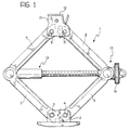
- Figure 1 shows a jack according to the invention;
- Figure 2 is a partial perspective view of a portion of the jack of Figure 1;
- Figure 3 is a partial perspective view of a variant of the jack according to the invention; and
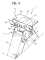
- Figure 4 is a partial perspective view of a further variant of the invention.
- With reference to Figures 1 and 2, in the embodiment illustrated by way of example a
lifting jack 1 according to the invention includes abase element 2 for resting on the ground, with twolower arms 5 and 6 pivoted on it at 3 and 4. Twofurther arms arms 5 and 6. The upper ends of thearms element 11. - A
support bracket 12, intended to be applied to an engagement surface of the car, is connected to the connectingelement 11 in ways which will be described in detail later. - A screw-type control and adjustment device, indicated 13 in Figure 1 and of a type which is known per se, is fixed to the pivotal connections between the
lower arms 5, 6 and theupper arms control lever 14 this device enables the configuration of the articulated parallelogram formed by the arms 5-8 to be adjusted so as to alter the height of thesupport bracket 12. - In the embodiment illustrated in Figure 2, the connecting
element 11 has two parallel, facingside portions 11a between which theupper arms - These portions are joined by an upper portion the surface of which is substantially a convex dihedral shape having two
faces line 11d which is substantially perpendicular to the pivot axes between the arms 5-8. - The
support bracket 12 of Figure 2 has an essentially rectangularflat support surface 12a resting on the top of the connectingelement 11. A U or V-section channel-shape portion 12b is joined to theflat support surface 12a of thebracket 12 with its concave surface facing upwards.
This channel-shaped portion is intended to be engaged with a corresponding rib or fillet on the bottom of a car. - Two downwardly folded
side tongues 12c extend from the shorter sides of thesupport portion 12a of thebracket 12, with only one being visible in Figure 2. Thesetongues 12c have respective vertically elongate apertures orslots 12d through which extend with clearance the ends of a transverse retaining pin ordowel 15 carried by the connectingelement 11. This pin or dowel is parallel to the pivot axes between the arms 5-8. The pin may be engaged in corresponding apertures in the connecting element or be otherwise fixed thereto, for example by welding. - As a result of the clearance between the
apertures 12d in the bracket and the ends of the pin ordowel 15, thesupport bracket 12 is pivotable about an axis perpendicular to the pivot axes between the arms 5-8. - Owing to the dihedral shape of the top of the connecting
element 11, thebracket 12 tends to assume two stable working positions in which itsportion 12a rests on thetop surface 11b or on thetop surface 11c respectively of the connectingelement 11 and is able to assume all intermediate positions between these two extreme stable positions. - The ability of the support stirrup 12 to turn or pivot transversely, together with its ability to pivot about the axis of the
pin 15, enables the bracket to be easily, accurately and securely engaged with the engagement surface of the car. - Figure 3 shows a first variant of the invention. In this drawing, parts and elements which have already been described have been given the same reference numerals.
- In the variant of Figure 3, the connecting
element 11 has a substantially planartop portion 11b. Thesupport bracket 12 has atop portion 12a having a lower arcuate,convex surface 12e resting on thetop surface 11b of the connectingelement 11. The engagement between theinternal tongues 12c of thebracket 12 and the pin ordowel 15 is substantially the same as described with reference to Figure 2. - In the variant of Figure 3 once again, the
support bracket 12 is substantially pivotable about an axis perpendicular to the pivot axes between the arms 5-8. - Figure 4 shows a further variant of the invention. In this drawing once again parts and elements which have already been described have been given the same reference numerals.
- In the variant of Figure 4, the
connecting element 11 is substantially identical to that described with reference to Figure 2. Once again, thesupport bracket 12 has a planar upper surface resting on the dihedral top portion of the connectingelement 11. - However this bracket has no lateral tongues but is pivoted on the connecting
element 11 by means of a pin or the like 16 the axis of which is perpendicular to the pivot axes between the arms 5-8. - In the variant of Figure 4 the
support bracket 12 is once again pivotable about an axis perpendicular to those of the pivotal connections between the aforesaid arms. - Naturally, the principle of the invention remaining unchanged, embodiments and manufacturing details may vary widely from those described and illustrated purely by way of non-limitative example, without departing thereby from the scope of the invention.
Claims (8)
- A lifting jack (1) for a car which includes at least one lower arm (5, 6) and at least one upper arm (7, 8) pivotally connected to each other,
a support bracket (12) connected to the upper arm (7, 8) to be applied to an engagement surface of the car, and
control and adjustment means (13, 14) connected to the said arms (5-8) and operable to adjust their positions relative to each other;
the lifting jack being characterised in that the support bracket (12) is connected to the said at least one upper arm (7, 8) so as to be pivotable about an axis perpendicular to the pivot axes between the said arms (5 to 8). - A jack according to Claim 1, characterised in that the said at least one upper arm (7, 8) has an associated bearing element (11) with an upper surface (11b, 11c) on which bears a lower surface (12a; 12e) of the support bracket (12); at least one of the said surfaces (11b, 11c; 12a, 12e) being shaped so as to cooperate with the other to define at least two different possible working positions of the support bracket (12).
- A jack according to Claim 2, characterised in that the upper surface (11b, 11c) of the said bearing element (11) has a substantially convex dihedral shape.
- A jack according to Claim 2, characterised in that the upper surface (11b) of the said bearing element (11) is substantially planar, and the support bracket (12) has an arcuate, convex lower surface (12e) which cooperates with the said planar surface (11b) of the bearing element (11).
- A jack according either to Claim 3 or Claim 4, characterised in that the support bracket (12) has a pair of apertures or slots (12d) engageable with clearance by a pin or dowel (15) fixed to the bearing element (11) and parallel to the pivot axes between the arms (5-8).
- A jack according to either Claim 3 or Claim 3, characterised in that the support bracket (12) is pivoted on a bearing surface (11) associated with the said at least one upper arm (7, 8) by a pin (16) arranged perpendicular to the pivot axes between the said arms (5-8).
- A jack according to any one of the preceding Claims, which includes two lower arms (5, 6) and two upper arms (7, 8) connected to each other so as to form an articulated parallelogram.
- A jack according to Claim 7 and any one of Claims 3 to 6, characterised in that the bearing element (11) is constituted by a connecting element (11) on which are pivoted the ends of the upper arms (7, 8) remote from the lower arms (5, 6).
Applications Claiming Priority (2)
| Application Number | Priority Date | Filing Date | Title |
|---|---|---|---|
| ITTO950427 | 1995-05-26 | ||
| IT95TO000427A IT1279749B1 (en) | 1995-05-26 | 1995-05-26 | LIFTING JACK FOR A VEHICLE. |
Publications (1)
| Publication Number | Publication Date |
|---|---|
| EP0744375A1 true EP0744375A1 (en) | 1996-11-27 |
Family
ID=11413593
Family Applications (1)
| Application Number | Title | Priority Date | Filing Date |
|---|---|---|---|
| EP96108252A Withdrawn EP0744375A1 (en) | 1995-05-26 | 1996-05-23 | A lifting jack for a car |
Country Status (2)
| Country | Link |
|---|---|
| EP (1) | EP0744375A1 (en) |
| IT (1) | IT1279749B1 (en) |
Cited By (4)
| Publication number | Priority date | Publication date | Assignee | Title |
|---|---|---|---|---|
| KR100578574B1 (en) | 2004-06-01 | 2006-05-12 | 기아자동차주식회사 | Device of Slanting Stand of Mechanical Jack |
| WO2010056218A1 (en) * | 2008-11-11 | 2010-05-20 | Arikan Kriko Ve Makina Sanayi Ticaret Anonim Sirketi | Load support for a jack, having bended parts |
| CN103130146A (en) * | 2013-03-06 | 2013-06-05 | 宁波天益齿轴齿轮有限公司 | Jack with separable support arms |
| CN114195038A (en) * | 2021-12-16 | 2022-03-18 | 孙岩 | Hydraulic lifting fastening device for automobile maintenance and use method thereof |
Citations (6)
| Publication number | Priority date | Publication date | Assignee | Title |
|---|---|---|---|---|
| US2672243A (en) * | 1951-10-17 | 1954-03-16 | Ben Goldberg | Jack with adjustable load-receiving table |
| DE3724113A1 (en) * | 1986-12-09 | 1988-06-16 | Tub Sa | Mechanical jack for lifting automobiles |
| EP0469234A1 (en) * | 1990-07-30 | 1992-02-05 | Tub S.A. | Vehicle lifting jack |
| EP0529355A1 (en) * | 1991-08-22 | 1993-03-03 | AUGUST BILSTEIN GMBH & CO. KG | Vehicle jack |
| EP0622329A1 (en) * | 1993-03-30 | 1994-11-02 | Tub S.A. | Automatic stabilizing and reinforcing device for vehicle raising jacks |
| DE9418720U1 (en) * | 1994-11-24 | 1995-01-12 | Panne Gmbh & Co Kg Grundstueck | Vehicle jacks |
-
1995
- 1995-05-26 IT IT95TO000427A patent/IT1279749B1/en active IP Right Grant
-
1996
- 1996-05-23 EP EP96108252A patent/EP0744375A1/en not_active Withdrawn
Patent Citations (6)
| Publication number | Priority date | Publication date | Assignee | Title |
|---|---|---|---|---|
| US2672243A (en) * | 1951-10-17 | 1954-03-16 | Ben Goldberg | Jack with adjustable load-receiving table |
| DE3724113A1 (en) * | 1986-12-09 | 1988-06-16 | Tub Sa | Mechanical jack for lifting automobiles |
| EP0469234A1 (en) * | 1990-07-30 | 1992-02-05 | Tub S.A. | Vehicle lifting jack |
| EP0529355A1 (en) * | 1991-08-22 | 1993-03-03 | AUGUST BILSTEIN GMBH & CO. KG | Vehicle jack |
| EP0622329A1 (en) * | 1993-03-30 | 1994-11-02 | Tub S.A. | Automatic stabilizing and reinforcing device for vehicle raising jacks |
| DE9418720U1 (en) * | 1994-11-24 | 1995-01-12 | Panne Gmbh & Co Kg Grundstueck | Vehicle jacks |
Cited By (6)
| Publication number | Priority date | Publication date | Assignee | Title |
|---|---|---|---|---|
| KR100578574B1 (en) | 2004-06-01 | 2006-05-12 | 기아자동차주식회사 | Device of Slanting Stand of Mechanical Jack |
| WO2010056218A1 (en) * | 2008-11-11 | 2010-05-20 | Arikan Kriko Ve Makina Sanayi Ticaret Anonim Sirketi | Load support for a jack, having bended parts |
| US8579258B2 (en) | 2008-11-11 | 2013-11-12 | Arikan Kriko Ve Makina Sanayi Ticaret Anonim Sirketi | Integral load support for a jack formed of a sheet material bent to less than 180° |
| CN103130146A (en) * | 2013-03-06 | 2013-06-05 | 宁波天益齿轴齿轮有限公司 | Jack with separable support arms |
| CN114195038A (en) * | 2021-12-16 | 2022-03-18 | 孙岩 | Hydraulic lifting fastening device for automobile maintenance and use method thereof |
| CN114195038B (en) * | 2021-12-16 | 2023-08-08 | 孙岩 | Hydraulic lifting fastening device for automobile maintenance and application method thereof |
Also Published As
| Publication number | Publication date |
|---|---|
| IT1279749B1 (en) | 1997-12-16 |
| ITTO950427A0 (en) | 1995-05-26 |
| ITTO950427A1 (en) | 1996-11-26 |
Similar Documents
| Publication | Publication Date | Title |
|---|---|---|
| EP1274595B1 (en) | Axle clamp attachment system | |
| JPH10503990A (en) | Suspension for rigid vehicle axle | |
| JPH0873194A (en) | Vehicular elevator cage | |
| WO1999020560A1 (en) | A lifting device with a liftable and tiltable platform | |
| GB2070162A (en) | Folding Wheel Chock | |
| EP0744375A1 (en) | A lifting jack for a car | |
| EP0221911B1 (en) | Jack | |
| CN1194926A (en) | Frame brace universal mounting bracket assembly | |
| JPH04266398A (en) | Vehicular jack | |
| EP0151154B1 (en) | Fifth wheel | |
| DE3603311C2 (en) | ||
| US5516066A (en) | Load rest for pantograph jack | |
| US6471009B1 (en) | Universal saddle for lift | |
| CA1216406A (en) | Connecting device for wiper blades | |
| EP0774440B1 (en) | One-piece load rest | |
| CN1438951A (en) | Wiper arm for automobiles | |
| US4720081A (en) | Screw drive six link side lift vehicle jack assembly | |
| CA2120191A1 (en) | Stabilizing and reinforcing device for vehicle-raising jacks | |
| EP0773186B1 (en) | Improved trunnion for use with a pantograph jack | |
| EP1340711B1 (en) | Lift apparatus having an articulated double parallelogram boom assembly | |
| EP0822106B1 (en) | Spring carrier arm for a vehicle spring system | |
| JP2843836B2 (en) | Z-shaped pantograph | |
| EP0032809A1 (en) | Platform and stop bar assembly | |
| JPS59186516A (en) | Couch | |
| US20020134972A1 (en) | Car jack |
Legal Events
| Date | Code | Title | Description |
|---|---|---|---|
| PUAI | Public reference made under article 153(3) epc to a published international application that has entered the european phase |
Free format text: ORIGINAL CODE: 0009012 |
|
| AK | Designated contracting states |
Kind code of ref document: A1 Designated state(s): DE ES FR GB SE |
|
| 17P | Request for examination filed |
Effective date: 19970412 |
|
| 17Q | First examination report despatched |
Effective date: 19990408 |
|
| STAA | Information on the status of an ep patent application or granted ep patent |
Free format text: STATUS: THE APPLICATION IS DEEMED TO BE WITHDRAWN |
|
| 18D | Application deemed to be withdrawn |
Effective date: 20000509 |