EP0743412A1 - Profiled lock cylinder - Google Patents
Profiled lock cylinder Download PDFInfo
- Publication number
- EP0743412A1 EP0743412A1 EP96107056A EP96107056A EP0743412A1 EP 0743412 A1 EP0743412 A1 EP 0743412A1 EP 96107056 A EP96107056 A EP 96107056A EP 96107056 A EP96107056 A EP 96107056A EP 0743412 A1 EP0743412 A1 EP 0743412A1
- Authority
- EP
- European Patent Office
- Prior art keywords
- key
- profile cylinder
- information
- cylinder according
- core
- Prior art date
- Legal status (The legal status is an assumption and is not a legal conclusion. Google has not performed a legal analysis and makes no representation as to the accuracy of the status listed.)
- Granted
Links
Images


Classifications
-
- E—FIXED CONSTRUCTIONS
- E05—LOCKS; KEYS; WINDOW OR DOOR FITTINGS; SAFES
- E05B—LOCKS; ACCESSORIES THEREFOR; HANDCUFFS
- E05B47/00—Operating or controlling locks or other fastening devices by electric or magnetic means
- E05B47/06—Controlling mechanically-operated bolts by electro-magnetically-operated detents
- E05B47/0611—Cylinder locks with electromagnetic control
- E05B47/0619—Cylinder locks with electromagnetic control by blocking the rotor
- E05B47/0626—Cylinder locks with electromagnetic control by blocking the rotor radially
- E05B47/063—Cylinder locks with electromagnetic control by blocking the rotor radially with a rectilinearly moveable blocking element
-
- E—FIXED CONSTRUCTIONS
- E05—LOCKS; KEYS; WINDOW OR DOOR FITTINGS; SAFES
- E05B—LOCKS; ACCESSORIES THEREFOR; HANDCUFFS
- E05B47/00—Operating or controlling locks or other fastening devices by electric or magnetic means
- E05B47/0001—Operating or controlling locks or other fastening devices by electric or magnetic means with electric actuators; Constructional features thereof
- E05B2047/0014—Constructional features of actuators or power transmissions therefor
- E05B2047/0015—Output elements of actuators
-
- E—FIXED CONSTRUCTIONS
- E05—LOCKS; KEYS; WINDOW OR DOOR FITTINGS; SAFES
- E05B—LOCKS; ACCESSORIES THEREFOR; HANDCUFFS
- E05B47/00—Operating or controlling locks or other fastening devices by electric or magnetic means
- E05B47/0001—Operating or controlling locks or other fastening devices by electric or magnetic means with electric actuators; Constructional features thereof
- E05B47/0002—Operating or controlling locks or other fastening devices by electric or magnetic means with electric actuators; Constructional features thereof with electromagnets
- E05B47/0003—Operating or controlling locks or other fastening devices by electric or magnetic means with electric actuators; Constructional features thereof with electromagnets having a movable core
- E05B47/0004—Operating or controlling locks or other fastening devices by electric or magnetic means with electric actuators; Constructional features thereof with electromagnets having a movable core said core being linearly movable
-
- E—FIXED CONSTRUCTIONS
- E05—LOCKS; KEYS; WINDOW OR DOOR FITTINGS; SAFES
- E05B—LOCKS; ACCESSORIES THEREFOR; HANDCUFFS
- E05B47/00—Operating or controlling locks or other fastening devices by electric or magnetic means
- E05B47/0001—Operating or controlling locks or other fastening devices by electric or magnetic means with electric actuators; Constructional features thereof
- E05B47/0012—Operating or controlling locks or other fastening devices by electric or magnetic means with electric actuators; Constructional features thereof with rotary electromotors
Abstract
Description
Die vorliegende Erfindung betrifft einen Profilzylinder mit einem kreiszylindrischen und den Schließkern aufnehmenden sowie mit einem daran befindlichen stegartig angesetzten Bereich, wobei im kreiszylindrischen Bereich radial in Richtung zum Schlüsselkanal weisende Zuhaltungen angeordnet und elastisch abgestützt sind.The present invention relates to a profile cylinder with a circular-cylindrical area receiving the locking core and with a web-like area located thereon, with tumblers arranged radially in the direction of the key channel and being elastically supported in the circular-cylindrical area.
Derartiger Profilzylinder ist beispielsweise bekannt aus der DE 43 36 476.Such profile cylinder is known for example from DE 43 36 476.
Der Vorteil dieses bekannten Profilzylinders liegt insbesondere in den vielfältigen Variationsmöglichkeiten, da die radial orientierten Zuhaltungen auch mehrfach innerhalb einer Zuhaltungsebene vorgesehen sein können.The advantage of this known profile cylinder lies in particular in the wide range of possible variations, since the radially oriented tumblers can also be provided multiple times within one tumbler plane.
Es ist allerdings davon auszugehen, daß im Rahmen der vorliegenden Anmeldung nicht nur Anordnungen für die Zuhaltungen nach obiger DE 43 36 476 sondern jegliche Zuhaltungen umfaßt werden sollen, die radial in Richtung zum Schlüsselkanal und lediglich im kreiszylindrischen Bereich des Profilzylinders vorgesehen sind.However, it must be assumed that the scope of the present application should not only include arrangements for the tumblers according to DE 43 36 476 above, but also any tumblers that are provided radially in the direction of the key channel and only in the circular cylindrical region of the profile cylinder.
Die bei diesen Profilzylindern erzielbare kompakte Bauweise gestattet trotz einer erhöhten Sicherheit durch erhöhte Zahl von Variationen noch nicht eine elektronisch gesicherte Benutzerkennung, die erst durch Einbringen einer elektronischen Information entscheidet, ob der Schließkern überhaupt vom eingesteckten Schlüssel betätigt werden darf.The compact design that can be achieved with these profile cylinders, despite increased security due to an increased number of variations, does not yet permit electronically secured user identification, which can only be achieved by introducing an electronic one Information decides whether the locking core can be actuated at all by the inserted key.
Eine derartige elektronische Benutzerkennung ist im Zuge zunehmender Sicherheitsanforderungen in einer innerhalb des Profilzylinders integrierten Bauform nur für Fälle realisiert worden, bei denen die zusätzliche elektronische Information am Schlüssel eine unerwünscht hohe Schlüssellänge hervorruft.Such an electronic user ID has only been implemented in the course of increasing security requirements in a design integrated within the profile cylinder for cases in which the additional electronic information on the key causes an undesirably long key length.
Es ist daher Aufgabe der Erfindung, den bekannten Profilzylinder mit seiner kompakten radialen Anordnung von Zuhaltungen so weiterzubilden, daß er unabhängig von der mechanischen Zuhaltung erst bei Vorliegen einer vorgegebenen und als Zutrittsberechtigung erkennbaren Information betätigbar ist.It is therefore an object of the invention to develop the known profile cylinder with its compact radial arrangement of tumblers in such a way that it can only be actuated independently of the mechanical tumbler when a given information item that can be recognized as access authorization is present.
Diese Aufgabe wird bei dem eingangs erwähnten Profilzylinder dadurch gelöst, daß zusätzlich zu den Zuhaltungen im kreiszylindrischen Bereich im Stegbereich ein derart beweglich angetriebenes Sperrelement vorgesehen ist, daß das Sperrelement in einer Schließstellung in die Drehbeweglichkeit des Schließkerns drehverhindert eingreift, sowie in einer Offenstellung den Schließkern freigibt, wobei das Sperrelement mit einem Antrieb zwischen Schließ- und Offenstellung getrieblich verbunden ist und wobei der Antrieb in Abhängigkeit von auf dem Schlüssel angebrachter Information steuerbar ist. Die Anordnung des Sperrelements im Stegbereich erzwingt daher keine Verringerung der Anzahl der Zuhaltungen. Das Sperrelement schafft bei kurzer Länge des Profilzylinders eine zusätzliche Zuhaltestelle die unabhängig von der Anzahl mechanischer Zuhaltungen ist. Das Sperrelement wird außerhalb der Zuhaltungsreihen und vorzugsweise dort im Schließzylinder angeordnet, wo der Schließkern eine Durchbruchstelle in Umfangsrichtung aufweist.This object is achieved in the profile cylinder mentioned at the outset in that, in addition to the tumblers in the circular-cylindrical area in the web area, a locking element which is driven in such a movable manner is provided that the locking element engages in a closed position in the rotational mobility of the locking core, and in an open position releases the locking core , wherein the locking element is operatively connected to a drive between the closed and open positions and wherein the drive can be controlled in dependence on information attached to the key. The arrangement of the locking element in the web area therefore does not force a reduction in the number of tumblers. With a short length of the profile cylinder, the locking element creates an additional locking point that is independent of the number of mechanical locking devices. The locking element is arranged outside the tumbler rows and preferably in the locking cylinder where the locking core has a breakthrough point in the circumferential direction.
Aus der Erfindung ergibt sich der Vorteil, daß neben einer erhöhten Sicherheit durch die radialen Zuhaltungen im kreiszylindrischen Bereich des Profils der gesamte bisher nicht genutzte stegartige Bereich derartigen Profilzylinders zur Aufnahme eines motorisch angetriebenen Sperrelements nebst zugehöriger Ansteuerschaltung ausgenutzt werden kann, wobei zugehörige Energiespeicher ggfs. auch noch dort angeordnet werden können.The advantage of the invention is that, in addition to increased security due to the radial tumblers in the circular cylindrical region of the profile, the entire previously unused web-like region of such profile cylinders for receiving a motor-driven locking element can be used in addition to the associated control circuit, with the associated energy store possibly also being arranged there.
Dabei ist von wesentlicher Bedeutung, daß das motorisch angetriebene Sperrelement an seinem Schließkern zusätzlich zu den radialen Zuhaltungen angreift. Hierdurch entsteht eine doppelte Sicherheit gegen unerlaubtes Öffnen, weil auch bei mechanisch richtigem Schlüssel zwar die Zuhaltungen geöffnet werden, jedoch die elektrisch angetriebene Sperre unbeeinflußt in den Schließkern eingreift. Erst bei Vorliegen der richtigen Kombination aus Schlüsseleinschnitten zum Ausrichten der Zuhaltungen mit der richtigen elektrischen, elektromagnetischen, elektrotechnischen od.dgl. Information zur Ansteuerung des Sperrelements wird der Schließkern freigegeben und erst dann läßt sich der Schließkern drehen. Im Rahmen vorliegender Anmeldung wird unter dem Begriff "Zuhaltung" eine Anordnung aus wenigstens zwei stirnseitig aneinanderliegenden Stiften verstanden, die zusammen mit einer Feder lediglich im kreiszylindrischen Bereich des Schließzylinders sitzen und die in einer den Profilzylinder und den Schließkern durchsetzenden Bohrung von der Feder in Vorzugslage gehalten werden. Wesentlich für diese Zuhaltungen ist die Tatsache, daß erst nach Einstecken des richtigen Schlüssels die daran vorgesehen Schlüsseleinschnitte die Zuhaltungen in ihrer Bohrung so verschieben, daß die Teilungsebene der benachbarten Stifte in der Drehebene zwischen Schließkern und umgebenden Zylindergehäuse liegt.It is essential that the motor-driven locking element acts on its closing core in addition to the radial tumblers. This creates a double security against unauthorized opening, because although the tumblers are opened even with a mechanically correct key, the electrically driven lock engages in the locking core unaffected. Only when there is the right combination of key cuts to align the tumblers with the right electrical, electromagnetic, electrotechnical or the like. The locking core is released to control the locking element and only then can the locking core be rotated. In the context of the present application, the term “tumbler” is understood to mean an arrangement of at least two pins lying against one another on the end face, which together with a spring are only seated in the circular-cylindrical region of the locking cylinder and which are held in a preferred position by the spring in a bore passing through the profile cylinder and the locking core become. Essential for these tumblers is the fact that only after inserting the correct key, the key cuts provided on it shift the tumblers in their bore so that the parting plane of the adjacent pins lies in the plane of rotation between the locking core and the surrounding cylinder housing.
Das Sperrelement kann türaußenseitig oder türinnenseitig vorgesehen sein. Besonders vorteilhaft ist die türaußenseitige Anordnung, da dann der dort befindliche Schließkern mittels des Sperrelements zusätzlich einbruchgesichert ist. Bevorzugt wird für das Sperrelement ein elektrischer oder elektromotorischer Antrieb vorgesehen. Hierbei kann es sich auch um einen elektromagnetischen Antrieb handeln. Geht man allerdings davon aus, daß das Sperrelement lediglich eine Schließstellung sowie eine Offenstellung benötigt, kann für den Antrieb des Sperrelements eine elektromotorisch angetriebene Kurbel vorgesehen sein, die zwischen einem oberen und einem unterem Totpunkt hin und her drehbar ist. Hierfür können geeignete Micromotoren, ggfs. über Untersetzungsgetriebe auf die Kurbel wirkend, vorgesehen sein. Als elektrische Energiespeicher kommen Knopfzellen oder Hochleistungsbatterien in Betracht, z.B. vom Typ A 23,12 Volt.The locking element can be provided on the outside of the door or on the inside of the door. The arrangement on the outside of the door is particularly advantageous since the locking core located there is then additionally secured against burglary by means of the locking element. An electric or electromotive drive is preferably provided for the blocking element. This can also be an electromagnetic drive. However, if it is assumed that the locking element only requires a closed position and an open position, an electric motor-driven crank can be provided for driving the locking element, which crank is located between an upper and an upper bottom dead center is rotatable back and forth. Suitable micromotors can be provided for this, possibly acting on the crank via reduction gears. Button cells or high-performance batteries, for example of type A 23.12 volts, can be considered as electrical energy stores.
Bevorzugt sollen elektrische Energiespeicher türinnenseitig angeordnet werden um diese in den kalten Jahreszeiten vor Frost zu schützen, insbesondere um die Lebensdauer zu erhöhen.Electrical energy storage devices should preferably be arranged on the inside of the door in order to protect them from frost in the cold seasons, in particular to increase the service life.
Werden die für das Erkennen der Zutrittsberechtigung notwendigen Informationen am Schlüssel dort angebracht, wo auch die Ausnehmungen zum Ausrichten der Zuhaltungen liegen, läßt sich nicht nur ein Schließzylinder kurzer Baulänge sondern auch noch ein Schlüssel verwenden, dessen Länge nicht über die zum Betätigen der mechanischen Zuhaltungen notwendige Länge hinausgeht.If the information required for recognizing the access authorization is attached to the key where the recesses for aligning the tumblers are located, not only can a lock cylinder of short overall length be used, but also a key whose length is not longer than that required to actuate the mechanical tumblers Length goes out.
Im Extremfall liegt der Informationsträger ausschließlich innerhalb des Schlüssellängsbereichs, der auch die Ausnehmungen zum Ausrichten der Zuhaltungen trägt.In extreme cases, the information carrier lies exclusively within the longitudinal key area, which also carries the recesses for aligning the tumblers.
Die Erfindung kann bei Profilzylindern mit Wendeschlüssel oder mit Nicht-Wendeschlüssel Anwendung finden.The invention can be used in profile cylinders with a reversible key or with a non-reversible key.
Besonders vorteilhaft ist die Verwendung von Nicht-Wendeschlüsseln, da einerseits die radial angeordneten Zuhaltungen bei dieser Art Profilzylinder für ausreichende Variationsmöglichkeit sorgen und der nicht mit Ausnehmungen versehene Bereich des Schlüsselrückens ohne weiteres den/die entsprechenden Informationsträger aufnehmen kann.The use of non-reversible keys is particularly advantageous, since on the one hand the radially arranged tumblers provide sufficient variation in this type of profile cylinder and the area of the key spine which is not provided with recesses can easily accommodate the corresponding information carrier (s).
Der Informationsträger läßt sich entweder berührungslos oder mechanisch abtasten. Bevorzugt wird die berührungslose Informationsabtastung wegen Verschleißfreiheit. Hierfür kommt insbesondere auch Lichtwellenabtastung in Frage.The information carrier can be scanned either without contact or mechanically. Non-contact information scanning is preferred because it is free of wear. Lightwave scanning is particularly suitable for this.
Eine bevorzugte Ausführungsform zeichnet sich dadurch aus, daß der Schlüsselkanal die Wandung des Schließkerns in Richtung zum Stegbereich des Profilzylinders durchbricht. Dies hat fertigungstechnische Vorteile für die Herstellung des Schließkerns. Dann sind im Bereich der Durchbruchstelle am ortsfesten Teil des Profilzylinders sowie an der hierzu korrespondierenden Stelle des Schlüsselrückens einerseits der Informationsträger und andererseits die Informationsleseeinrichtung anzubringen. Hierdurch lassen sich nicht nur zusätzliche Übertragungselemente einsparen, sondern es wird auch die abgespeicherte Information unmittelbar übertragen, erkannt und für die Steuerung verwendet.A preferred embodiment is characterized in that the key channel in the wall of the locking core in Breaks through towards the web area of the profile cylinder. This has manufacturing advantages for the manufacture of the locking core. Then on the one hand the information carrier and on the other hand the information reading device are to be attached in the area of the breakthrough point on the stationary part of the profile cylinder and at the corresponding point on the back of the key. This not only saves additional transmission elements, but also the stored information is immediately transmitted, recognized and used for the control.
Eine Weiterbildung der Erfindung sieht vor, die Sperre gabelförmig auszubilden. Hierdurch entstehen zwei Sperrzapfen, die in den Schließkern eingreifen. Die Gabel steht dabei mit ihren Zinken im wesentlichen so, daß die beiden Zinken zu unterschiedlichen Seiten der den Stegbereich mittig schneidenden Axialebene liegen.A further development of the invention provides for the lock to be in the form of a fork. This creates two locking pins that engage in the locking core. The fork with its tines is essentially such that the two tines lie on different sides of the axial plane that intersects the web region in the middle.
Ordnet man darüber hinaus den Informationsträger am Schlüssel so an, daß er seine ortsfeste zugehörige Leseeinrichtung am Profilzylinder überfährt, bevor der eingesteckte Schlüssel auf Endanschlag gefahren ist, bietet dies zusätzlichen Vorteil: für das Lesen und Verarbeiten der Information "Zugangsberechtigung" sowie für die Ansteuerung des Antriebs und das Verfahren des Sperrelements in die Offenstellung, ist eine gewisse Zeit zu veranschlagen. Während dieser Zeit darf der Schlüssel mit dem Schließkern nicht verdreht werden, da ansonsten das Sperrelement an der Trennfuge zwischen Schließkern und Zylindergehäuse eingeklemmt würde.If one also arranges the information carrier on the key so that it runs over its stationary associated reading device on the profile cylinder before the inserted key has reached the end stop, this offers an additional advantage: for reading and processing the information "access authorization" and for controlling the The drive and the movement of the locking element into the open position must be estimated for a certain time. During this time, the key with the locking core must not be turned, otherwise the locking element would be jammed at the joint between the locking core and the cylinder housing.
Sieht man allerdings vor, die zugehörige Information zur Ansteuerung des Sperrelements zu übermitteln, bevor die Zuhaltungen mechanisch entriegelt sind (= Endstellung des Schlüssels) so ist diese Gefahr beseitigt. Die motorisch angetriebene Sperre wird geöffnet sein, bevor die mechanische Öffnung der Zuhaltungen erfolgt ist.However, if one provides to transmit the associated information for activating the locking element before the tumblers are mechanically unlocked (= end position of the key), this danger is eliminated. The motorized lock will be opened before the tumblers are mechanically opened.
Im folgenden wird die Erfindung anhand von Ausführungsbeispielen näher erläutert. Es zeigen:
- Fig.1
- ein erstes Ausführungsbeispiel der Erfindung im Prinzip,
- Fig.1a
- Querschnitt des Ausführungsbeispiels in Fig.1 entlang der Linie II-II
- Fig.2
- ein weiteres Ausführungsbeispiel der Erfindung,
- Fig.3
- ein Ausführungsbeispiel der Erfindung mit zeitlich vor Erreichen des Endanschlags erfolgter Informationsübertragung,
- Fig.3a
- Querschnitt des Ausführungsbeispiels in Fig.3 entlang der Linie III-III, und
- Fig.4
- Sperrelement mit elektromagnetischem Antrieb.
- Fig. 1
- a first embodiment of the invention in principle,
- Fig.1a
- Cross section of the embodiment in Figure 1 along the line II-II
- Fig. 2
- another embodiment of the invention,
- Fig. 3
- 1 an embodiment of the invention with information being transmitted before the end stop has been reached,
- Fig.3a
- Cross section of the embodiment in Figure 3 along the line III-III, and
- Fig. 4
- Locking element with electromagnetic drive.
Sofern im folgenden nichts anderes gesagt ist, gilt die folgende Beschreibung stets für alle Figuren.Unless otherwise stated below, the following description always applies to all figures.
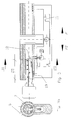
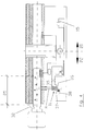
Die Figuren zeigen einen Profilzylinder 1. Derartiger Profilzylinder steht, wie die Querschnittszeichnungen der Fig.1a,3a zeigen aus einem kreiszylindrischen Bereich 2 sowie einem daran angesetzten stegartigen Bereich 3. Das Außengehäuse des Profilzylinders ist einstückig ausgebildet. Der kreiszylindrische Bereich des Profilzylinders ist daher materialeinheitlich mit dem stegartig angesetzten Bereich 3 gefertigt.The figures show a
Der kreiszylindrische Bereich 2 dient der Aufnahme des drehbaren Schließkerns 4. Aus fertigungstechnischen Gründen ist der drehbare Schließkern 4 innerhalb eines Rohres 5 drehbar gelagert. Das Rohr 5 ist innerhalb des kreiszylindrischen Bereichs 2 fest angeordnet. Das Rohr 5 weist radiale Bohrungen auf, die mit Bohrungen des Schließkerns 4 fluchten und in denen die Zuhaltungen 6 mitsamt ihren Federn stecken.The circular
Von wesentlicher Bedeutung für die Erfindung ist die Tatsache, daß die Zuhaltungen 6 lediglich und auf diese Weise im kreiszylindrischen Bereich 2 des Profilzylinders vorgesehen sind. Die vom Schlüssel betätigten Zuhaltungen sind daher nicht innerhalb des stegartig angesetzten Bereichs 3 zu finden.Of essential importance for the invention is the fact that the
An sich bekannt ist, daß derartige Zuhaltungen 6 elastisch abgestützt sind und von den Abstützelementen in einer Vorzugslage gehalten werden. Die Vorzugslage wird durch Einführen des Schlüssels in den Profilzylinder so geändert, daß die Zuhaltungen entlang der Bewegungsebene des Schließkerns 4 relativ zum umgebenden Rohr 5 so eingestellt werden, daß dort liegende Teilungsebenen der Zuhaltung eine Verdrehung des Schließkerns ermöglichen.It is known per se that tumblers 6 of this type are elastically supported and are held in a preferred position by the support elements. The preferred position is changed by inserting the key in the profile cylinder so that the tumblers along the plane of movement of the
Obwohl dies an sich bekannt ist, wird zusätzlich auf die DE 43 36 476 verwiesen. Bezüglich der hier nicht genannten Merkmale wird der Inhalt dieser Anmeldung auch zum Gegenstand der vorliegenden Anmeldung gemacht.Although this is known per se, reference is also made to DE 43 36 476. With regard to the features not mentioned here, the content of this application is also made the subject of the present application.
Weiterhin zeigen die Figuren, daß der Schließkern 4 in Längsrichtung von einem Schlüsselkanal 7 durchsetzt ist. Der Schlüsselkanal 7 hat eine hantelartige Querschnittsform (siehe Fig.1a) bzw. eine pilzförmige Querschnittsform (siehe Fig. 3a). Folglich ist die Erfindung weder auf Wendeschlüssel noch auf sogenannte Nicht-Wendeschlüssel beschränkt. In jedem Falle kommen alle Arten von Schlüsselkanalquerschnitten in Betracht, so lange der Profilzylinder lediglich radiale Zuhaltungen im kreiszylindrischen Bereich aufweist.Furthermore, the figures show that the locking
Wesentlich ist nun, daß zusätzlich zu den Zuhaltungen 6 im kreiszylindrischen Bereich 2 ein Sperrelement 8 vorgesehen ist. Das Sperrelement 8 ist im stegartig angesetzten Bereich des Profilzylinders beweglich geführt. Es handelt sich um einen quer zum Schließkern beweglichen Stift oder ähnliches, der zwischen einer Schließstellung 9 und einer Offenstellung 10 beweglich angetrieben ist. In der Sperrstellung 8 greift das Sperrelement 8 in die Drehbeweglichkeit des Schließkerns drehverhindert ein. In der Offenstellung gibt das Sperrelement 8 den Schließkern frei.It is now essential that, in addition to the
Hierzu ist fluchtend mit der Führung des Sperrelements 8 im stegartig angesetzten Bereich 3 des Profilzylinders 1 im Schließkern 4 eine Querbohrung angebracht. In diese Querbohrung greift die Spitze des Sperrelements 8 in der Schließstellung ein. In der Offenstellung 10 wird jedoch die Spitze des Sperrelements 8 soweit aus dem Schließkern herausgefahren, daß der formschlüssige Eingriff des Sperrelements 8 in den Schließkern 4 unterbleibt.For this purpose, a transverse bore is made in alignment with the guidance of the locking element 8 in the web-
Das Sperrelement 8 ist in den Fällen Fig.1 bis 3 mit einem Antrieb 11 getrieblich verbunden und wird von dem Antrieb 11 zwischen der Schließstellung 9 und der Offenstellung 10 gefahren. Hierzu besteht der Antrieb 11 aus einem ortsfest angeordneten Elektromotor, z.B. einem Gleichspannung-Micromotor. Der Micromotor ist ortsfest am stegartig angesetzten Bereich 4 des Profilzylinders gelagert.In the cases of FIGS. 1 to 3, the blocking element 8 is connected to a
Mit der Motorwelle 14 des Elektromotors 12 ist drehfest eine Kurbel 13 verbunden. Die Kurbel 13 trägt einen Exzenterstift 33, an welchem das untere Ende des Sperrelements 8 beweglich ist. Infolge der Drehbewegung der Kurbel 13 wird der Exzenterstift 33 auf einer Kreisbahn um die Motorwelle 14 herum geführt. Dabei ist das untere Ende des Sperrelements 8 ständig formschlüssig mit dem Exzenterstift 33 verbunden. Dieses ist wiederum im stegartigen Gehäuse des Profilzylinders 1 lediglich in Längsrichtung geführt, wobei der Kreuzkopf 34 den mit der Kurbeldrehung verschwenkenden unteren Teil des Sperrelements 8 vom ausschließlich linear geführten oberen Teil entkoppelt.A
Wesentlich ist auch, daß der Exzenterstift 33 so angetrieben sein kann, daß er zwischen seiner oberen Totpunktstellung und seiner unteren Totpunktstellung verfahren wird. In diesem Falle liegt die Schließstellung des Sperrelements 8 dann vor, wenn der Exzenterstift 33 seinen oberen Totpunkt eingenommen hat. Die Offenstellung ist dann gegeben, wenn der Exzenterstift 33 seinen unteren Totpunkt angefahren hat.It is also essential that the
Der Vorteil dieser Ausführung liegt darin, daß eine Manipulation von außen so gut wie nicht möglich ist. Da in der oberen Totpunktstellung alle Kräfte, die eine Bewegung der Sperre 8 in Längsrichtung bewirken könnten, exakt durch den Drehpunkt der Motorwelle 14 gehen, ist Manipulation am Sperrelement 8 nicht möglich.The advantage of this design is that external manipulation is practically impossible. Since in the top dead center position all forces that could cause a movement of the lock 8 in the longitudinal direction go exactly through the pivot point of the
Weiterhin ist wesentlich, daß der Antrieb 11 nur in Abhängigkeit von auf dem Schlüssel angeordneter Information steuerbar ist.It is also essential that the
Hierzu ist ortsfest am Profilzylinder 1 ein Informationsnehmer 19 vorgesehen, der mit einem auf dem Schlüsselrücken 27 angebrachten Informationsgeber 18 zusammenwirkt. Das Zusammenwirken geschieht prinzipiell derart, daß bei Vorbeifahren des Informationsgebers 18 am Schlüsselrücken an dem ortsfesten Informationsnehmer 19 des Profilzylinders eine auf dem Schlüssel vorgesehene Information abgetastet wird. Stimmt die Information des Informationsgebers mit einer vorbestimmten Information überein, so wird über die Steuereinheit 17 ein entsprechendes Schaltsignal an das Schaltrelais 16 übermittelt. Hierbei handelt es sich um ein allgemeines Schaltelement, z.B. Transistoranordnung, mit zwei stabilen Schaltzuständen. Das Schaltrelais 16 schließt den Stromkreis zwischen Batterie 15 und Elektromotor 12. Der Elektromotor vollzieht eine halbe Motorumdrehung. Infolgedessen wird das Sperrelement 8 aus dem Eingriff mit dem Schließkern 4 gefahren. Der Schließkern 4 kann daher gedreht werden, sobald die Zuhaltungen 6 in ihre Freigabestellung verlagert worden sind.For this purpose, an
In an sich bekannter Weise sind derartige Profilzylinder mit einer Stulpschraube 1a am Schloß im Türblatt befestigt. Sie weisen einen türinnenseitigen Bereich 21 sowie einen türaußenseitigen Bereich 20 auf. Der türaußenseitige Bereich soll nach dieser Erfindung bevorzugt das Sperrelement 8 nebst zugehörigen Antrieb 11 tragen. In bevorzugter Weiterbildung sollen jedoch die elektrischen Energiespeicher 15 am türinnenseitigen Längsbereich 21 des Profilzylinders sitzen. Dies bietet den Vorteil, daß auch bei extremen Niedrigtemperaturen der elektrische Energiespeicher 15 wärmegeschützt ist. Da es sich bevorzugt um eine kleine Batterie handelt, bleibt daher auch bei extremen Außentemperaturen die Funktionsfähigkeit des Profilzylinders voll erhalten.In a manner known per se, such profile cylinders are fastened to the lock in the door leaf with a faceplate screw 1a. They have an
Um darüber hinaus Manipulationen von außen bei geschlossener Tür zu verhindern, soll bevorzugt der Energiespeicher 15 erst nach Entfernen der Stulpschraube zugänglich sein. Daher kann ein Batterieaustausch nur bei geöffneter Tür erfolgen. Bei geschlossener Tür wäre die Stulpschraube 1a nicht zugänglich.In order to prevent manipulation from the outside when the door is closed, the
Hinsichtlich des Informationsgebers 18 am Schlüsselrücken 27 wird auf folgende Unterschiede hingewiesen.With regard to the
Gemäß Fig.1 liegt ein sogenannter Wendeschlüssel vor. Der Schlüsselkanal 7 ist symmetrisch. Derartiger Schlüssel kann in beiden möglichen Hochkantstellungen in den Schlüsselkanal 7 eingeführt werden.According to Figure 1, there is a so-called reversible key. The
Aus diesem Grunde ist der Informationsgeber 18 auf beiden Schlüsselrücken 27 anzuordnen. In diesem Falle wäre es unerheblich, ob der Schlüssel in der einen oder in der anderen Hochkantstellung in den Schlüsselkanal 7 eingesteckt würde.For this reason, the
Etwas anderes gilt für Schlüsselquerschnitte gemäß Fig. 3. Derartiger Schlüssel ist, wie anhand des Querschnitts des Schlüsselkanals erkennt, nicht symmetrisch. Er weist lediglich am oberen Bereich eine Verdickung auf, während der untere Schlüsselkanalbereich stegartig verläuft. In diesem Falle wäre der Informationsgeber 18 am Schlüsselrücken 27 lediglich auf dem stegartigen Schlüsselrücken anzubringen.Something else applies to key cross sections according to FIG. 3. Such a key, as can be seen from the cross section of the key channel, is not symmetrical. It only has a thickening at the upper area, while the lower key channel area is web-like. In this case, the
Der gegenüberliegende Schlüsselrücken weist keinen Informationsgeber 18 auf.The opposite key spine has no
Ein weiterer Unterschied besteht hinsichtlich der Ausführungen Fig.1 und Fig.3. Bekannterweise sind die Ausnehmungen zur Betätigung der Zuhaltungen 6 in einem vorbestimmten Längsbereich 25 des Schlüsselrückens angeordnet. Bei dem Ausführungsbeispiel gemäß Fig.1 ist der Informationsgeber 18 am vorderen Ende des Schlüssels und außerhalb dieses Längsbereichs 25 angebracht.There is a further difference with regard to the designs Fig. 1 and Fig. As is known, the recesses for actuating the
Bei den Ausführungsbeispielen gemäß Fig.2 und 3 sitzt der Informationsgeber 18 auch innerhalb (Fig.2) bzw. ausschließlich innerhalb (Fig.3) des Längsbereichs 25 mit den Ausnehmungen für die Zuhaltungen 6.In the exemplary embodiments according to FIGS. 2 and 3, the
Der Vorteil dieser Ausführungsform besteht darin, daß die Schlüssellänge insgesamt sehr kurz gehalten werden kann. Infolge der vielfältigen Variationsmöglichkeiten für die Zuhaltungen 6 bei dieser Art Schließzylinder kann daher der Informationsgeber 18 ohne Veränderung der herkömmlichen Schlüssellängen innerhalb des Längsbereichs 25 der Ausnehmungen angebracht sein.The advantage of this embodiment is that the overall key length can be kept very short. As a result of the various possible variations for the
Der Informationsaustausch zwischen Informationsgeber 18 und Informationsnehmer 19 kann entweder durch mechanische Abtastung oder bevorzugt auch berührungs- und damit verschleißlos erfolgen.The information exchange between the
Besonders vorteilhaft erweist sich die Tatsache, daß der Schließkern 4 von einem Schlüsselkanal 7 durchsetzt ist, der die Wandung des Schließkerns 4 dort durchbricht, wo der Schlüsselkanal in der Schlüsseleinschubstellung mit dem stegartig angesetzten Bereich 3 des Profilzylinders 1 kämmt. Alle Zuhaltungen 6 liegen außerhalb der Durchbruchstelle 26 in sogenannten Zuhaltungsreihen, die sich längs des Profilzylinders erstrecken.The fact that the locking
Daher kann die Oberfläche des Informationsnehmers 19 unmittelbar unterhalb derjenigen Stelle am Schlüsselrücken 27 zu liegen kommen, an welcher der Informationsaustausch zwischen Informationsgeber 18 und Informationsnehmer 19 zustandekommen soll.The surface of the
Der Vorteil liegt in einem ungehinderten und durch dazwischen liegende Materialien nicht störend abgeschirmten Informationsaustausch, weil sich die am Informationsaustausch beteiligten Informationsträger unmittelbar gegenüberliegen können.The advantage lies in an unhindered exchange of information, which is not disrupted by the intervening materials, because the information carriers involved in the information exchange can be directly opposite one another.
Zu diesem Zweck durchbricht der Schlüsselkanal 7 entlang eines Längsbereichs die Wandung des Schließkerns auf der dem Stegbereich 3 zugewandten Seite. Im Bereich der Durchbruchstelle 26 wird auf dem Schlüsselrücken 27 der Informationsgeber 18 angeordnet. Der Informationsnehmer 19 wird dann an der hierzu korrespondierenden Stelle des Rohres 5 ortsfest vorgesehen. Beim Vorbeifahren des Informationsgebers 18 infolge Einschub des Schlüssels kann daher der Informationsnehmer 19 die dort angebrachte Information abnehmen und an die Steuereinheit 17 übermitteln.For this purpose, the
Darüber hinaus zeigen Fig.1a und 3a daß das Sperrelement 8 gabelförmig ausgestaltet ist. Es greift mit zwei Gabelzinken 28 in den Schließkern 4 ein. Jeder der Gabelzinken 28 liegt dabei auf jeweils einer Seite des Schlüsselkanals 7. Hier wird der Schlüsselkanal jeweils seitlich angeschnitten. In diesen beiden Sekantialebenen 30,31 liegen die Einfahröffnungen der Gabelzinken. Dort erfolgt mit einfahrenden Gabelzinken 28 ein drehverhindernder Eingriff der Sperre 8 in den Schließkern 4. Dabei wird der Schlüsselrücken von jeweils einem der Gabelzinken auf jeweils einer seiner Seiten flankiert. Der Schlüssel sperrt also selbst die Drehung des Schließkerns, wenn die Gabelzinken eingefahren sind. Dies gilt auch für den Fall, daß ein manipulierter Schlüssel die richtigen mechanischen Kodierungen aufweisen sollte.1a and 3a also show that the blocking element 8 is designed in the form of a fork. It engages the locking
Zusätzlich zeigen die Figuren folgendes:In addition, the figures show the following:
Jeder Schlüssel weist einen Endanschlag 32 auf. Der Endanschlag dient einer Begrenzung der Einstecklänge des Schlüssels in den Schlüsselkanal 7. Wenn der Endanschlag 32 an der Stirnfläche des Schließkerns 4 angelangt ist, hat der Schlüssel seine Einsteckstellung erreicht. In der Einsteckstellung fluchten die Zuhaltungen 6 mit den Ausnehmungen im Längsbereich 25 am Schlüsselrücken 27. In dieser vollständigen Einsteckstellung werden die Zuhaltungen 6 geöffnet und es soll die Drehbewegung des Schließkerns freigegeben sein. Berücksichtigt man nun, daß vom Informationsaustausch zwischen Informationsgeber 18 und Informationsnehmer 19 von Beginn an eine gewisse Zeit erforderlich ist, um die im Eingriff befindliche Sperre 8 zu öffnen, so sollten die Zuhaltungen 6 erst dann betätigt werden können, wenn die Sperre 8 geöffnet ist. Das Öffnen der Sperre 8 soll daher zeitlich früher erfolgen als die Betätigung der Zuhaltungen 6.Each key has an
Zu diesem Zweck wird vorgeschlagen, daß der Informationsaustausch zwischen Informationsgeber 18 und Informationsnehmer 19 bereits dann erfolgt, wenn der Schlüssel mit seinem Endanschlag 32 noch nicht in der vollen Einsteckstellung ist. Es genügt prinzipiell, daß Informationsgeber und Informationsnehmer vor der Einsteckendstellung des Schlüssels im Schlüsselkanal 7 miteinander kämmen, z.B. durch relatives Vorbeigleiten aneinander. Fig.3 zeigt diese Situation zu Beginn des Einsteckens, während Fig.2 diese Situation kurz vor Ende des Einsteckens zeigt.For this purpose, it is proposed that the information exchange between the
Auf diese Weise wird sichergestellt, daß bei Verwendung eines zugelassenen Schlüssels die Sperre 8 bereits dann geöffnet ist, wenn die Ausnehmungen am Schlüsselrücken die Zuhaltungen 6 betätigen. Der drehverhindernde Eingriff zwischen Sperre 8 und Schließkern 4 ist daher bereits aufgehoben, wenn der Schlüssel seine Endstellung erreicht hat.In this way it is ensured that when using an approved key, the lock 8 is already open when the recesses on the back of the key actuate the
Insbesondere empfiehlt es sich jedoch, den Informationsnehmer 19 tief innerhalb des Schlüsselkanals vorzusehen, um mögliche Manipulationen von vornherein auszuschließen. Ein weiterer Vorteil ergibt sich dann aus der Tatsache, daß ein Verkanten des Schlüssels ausscheidet, weil der Schlüssel im Moment des Vorbeigleitens seines Informationsgebers 18 am Informationsnehmer 19 bereits tief genug im Schlüsselkanal 7 eingesteckt ist und somit eine sichere Längsführung hat.In particular, however, it is advisable to provide the
Zusätzlich zeigt Fig.4 eine alternative Ausführungsform für den Antrieb der Sperre 8.4 also shows an alternative embodiment for driving the lock 8.
In diesem Fall besteht der Antrieb 11 aus einer elektrischen Spule 35, die von einem Spulenkern 36 durchsetzt ist. Der Spulenkern taucht dabei in Spule 35 ein.In this case, the
Der Spulenkern ist in Längsrichtung innerhalb der Spulenwicklungen verschieblich. Um zwei definierte Endstellungen zu erzielen, dient die Totpunktfeder 37. Die Totpunktfeder 37 stützt sich mit einem Ende am Spulenkern ab während das andere Ende ortsfest sitzt. Legt man nun eine Spannung an die elektrische Spule 35, so wird der Kern abhängig von der Stromflußrichtung linear zu sich selbst verschoben. Dabei gerät die Totpunktfeder 37 in einer bestimmten Position in ihre Totpunktlage 38. In der Totpunktlage 38 hat die Totpunktfeder 37 ihre kürzeste Länge, so daß sie unmittelbar nach Überfahren der Totpunktlage 38 entspannt wird. Die Entspannung der Totpunktfeder erfolgt bis die Sperre 8 in der gegenüberliegenden Endstellung ist.The coil core is displaceable in the longitudinal direction within the coil windings. In order to achieve two defined end positions, the
Der Vorteil dieser Weiterbildung liegt darin, daß eine getriebliche Verbindung zwischen Antrieb 11 und Sperre 8 nicht erforderlich ist. Zusätzlich sorgt die Totpunktfeder 37 dafür, daß die Manipulation von außen erschwert wird.The advantage of this development is that a gear connection between
Soll die Sperre 8 in die gegenüberliegende Endstellung gefahren werden, so ist lediglich eine Umpolung der Spulenanschlüsse vorgesehen, wie gestrichelt gezeichnet.If the lock 8 is to be moved into the opposite end position, only a reversal of the polarity of the coil connections is provided, as shown in broken lines.
- 11
- ProfilzylinderProfile cylinder
- 1a1a
- StulpschraubeForend screw
- 22nd
- kreiszylindrischer Bereichcircular cylindrical area
- 33rd
- stegartig angesetzter Bereicharea set on the bridge
- 44th
- SchließkernLocking core
- 55
- Rohrpipe
- 66
- ZuhaltungenTumblers
- 77
- SchlüsselkanalKey channel
- 88th
- SperrelementLocking element
- 99
- SchließstellungClosed position
- 1010th
- OffenstellungOpen position
- 1111
- Antriebdrive
- 1212th
- ElektromotorElectric motor
- 1313
- Kurbelcrank
- 1414
- MotorwelleMotor shaft
- 1515
- Batteriebattery
- 1616
- Schaltelement, Transistoranordnung, bistabile SchaltvorrichtungSwitching element, transistor arrangement, bistable switching device
- 1717th
- SteuereinheitControl unit
- 1818th
- InformationsgeberInformation provider
- 1919th
- InformationsnehmerInformation taker
- 2020th
- türaußenseitiger LängsbereichLongitudinal area outside the door
- 2121
- türinnenseitiger LängsbereichLongitudinal area inside the door
- 2525th
- Längsbereich der AusnehmungenLongitudinal area of the recesses
- 2626
- DurchbruchstelleBreakthrough
- 2727
- SchlüsselrückenKey back
- 2828
- GabelzinkenForks
- 2929
- SchubstangePush rod
- 3030th
- erste Sekantialebenefirst secantial level
- 3131
- zweite Sekantialebenesecond secantial level
- 3232
- EndanschlagEnd stop
- 3333
- ExenterstiftEccentric pin
- 3434
- KreuzkopfCross head
- 3535
- elektrische Spuleelectric coil
- 3636
- SpulenkernCoil core
- 3737
- TotpunktfederDead center spring
- 3838
- TotpunktlageDead center position
Claims (19)
daß zusätzlich zu den Zuhaltungen (6) im kreiszylindrischen Bereich
im Stegbereich (3) ein derart beweglich angetriebenes Sperrelement (8) vorgesehen ist, daß dieses in einer Schließstellung (9) in die Drehbeweglichkeit des Schließkerns (4) drehverhindernd eingreift sowie in einer Offenstellung (10) den Schließkern (4) freigibt, wobei
das Sperrelement (8) von einem Antrieb (11) zwischen Schließ- und Offenstellung (9,10) verfahrbar ist und wobei der Antrieb (11) in Abhängigkeit von auf dem Schlüssel angeordneter Information (18) steuerbar ist.Profile cylinder (1) with a circular cylindrical (2) receiving area and the locking core (4) and with a web-like (3) attached to it, in the circular cylindrical area (2) pointing radially towards the key channel (7) and elastically supported tumblers ( 6) are arranged, characterized in that
that in addition to the tumblers (6) in the circular cylindrical area
In the web area (3) such a movably driven locking element (8) is provided that in a closed position (9) it engages in the rotational mobility of the closing core (4) to prevent rotation and in an open position (10) releases the closing core (4), whereby
the locking element (8) can be moved by a drive (11) between the closed and open positions (9, 10) and the drive (11) can be controlled as a function of information (18) arranged on the key.
Applications Claiming Priority (2)
| Application Number | Priority Date | Filing Date | Title |
|---|---|---|---|
| DE19517704A DE19517704C2 (en) | 1995-05-13 | 1995-05-13 | Profile cylinder |
| DE19517704 | 1995-05-13 |
Publications (2)
| Publication Number | Publication Date |
|---|---|
| EP0743412A1 true EP0743412A1 (en) | 1996-11-20 |
| EP0743412B1 EP0743412B1 (en) | 2006-07-19 |
Family
ID=7761898
Family Applications (1)
| Application Number | Title | Priority Date | Filing Date |
|---|---|---|---|
| EP96107056A Expired - Lifetime EP0743412B1 (en) | 1995-05-13 | 1996-05-06 | Profiled lock cylinder |
Country Status (3)
| Country | Link |
|---|---|
| EP (1) | EP0743412B1 (en) |
| AT (1) | ATE333549T1 (en) |
| DE (2) | DE19517704C2 (en) |
Cited By (7)
| Publication number | Priority date | Publication date | Assignee | Title |
|---|---|---|---|---|
| EP0743411A2 (en) * | 1995-05-15 | 1996-11-20 | CODATEX ID-Systeme Gesellschaft mbH | Locking device |
| DE29804066U1 (en) * | 1998-03-07 | 1999-07-22 | Bks Gmbh | Cylinder key |
| EP1369825A2 (en) * | 2002-06-06 | 2003-12-10 | Buga Schliesssysteme AG | Lock cylinder with wireless signal transmission |
| DE102004013196B3 (en) * | 2004-03-17 | 2005-07-07 | TST Tresor- und Schloßtechnik GmbH | Lock unit for electronic high security lock requiring input of electronic identifcation signals for release of blocking slider to permit movement of locking pins into released position |
| EP2886756A1 (en) | 2013-12-19 | 2015-06-24 | BKS GmbH | Locking cylinder |
| CN106958385A (en) * | 2017-05-04 | 2017-07-18 | 深圳奥登科技有限公司 | One kind has a spoon digital intelligent-controlled lock core |
| EP3339539A1 (en) * | 2016-12-14 | 2018-06-27 | BKS GmbH | Profile cylinder |
Families Citing this family (3)
| Publication number | Priority date | Publication date | Assignee | Title |
|---|---|---|---|---|
| US7987687B2 (en) | 2005-12-27 | 2011-08-02 | Keso Ag | Electromechanical rotary lock cylinder |
| DE102007000439A1 (en) * | 2007-08-13 | 2009-02-19 | Aug. Winkhaus Gmbh & Co. Kg | Electronically operated locking cylinder for use in door, has actuators and clutch casing arranged outside of housing, where casing exhibits diameter larger than outer shaft, and control element mounted to release movement of actuators |
| CN104033038B (en) * | 2014-06-23 | 2016-08-31 | 哈尔滨杜卡防盗安全系统技术开发有限公司 | A kind of can the auger formula electronic lock of long-distance remote control |
Citations (6)
| Publication number | Priority date | Publication date | Assignee | Title |
|---|---|---|---|---|
| GB2184772A (en) * | 1985-12-19 | 1987-07-01 | Bauer Kaba Ag | Locking device |
| GB2196685A (en) * | 1986-10-24 | 1988-05-05 | Yale Security Prod Ltd | Key-operable locks |
| EP0388997A1 (en) * | 1986-03-21 | 1990-09-26 | Emhart Industries, Inc. | Electronic locking system |
| FR2655367A1 (en) * | 1989-12-05 | 1991-06-07 | Vachette Sa | Mechanically and electrically secured double cylinder lock |
| DE4207160C1 (en) * | 1992-03-06 | 1993-02-11 | Aug. Winkhaus Gmbh & Co Kg, 4404 Telgte, De | |
| WO1993019267A1 (en) * | 1992-03-26 | 1993-09-30 | Assa Ab | Cylinder lock |
Family Cites Families (11)
| Publication number | Priority date | Publication date | Assignee | Title |
|---|---|---|---|---|
| NO152058C (en) * | 1982-07-01 | 1985-07-24 | Trioving As | LOCK WITH ELECTROMAGNETIC SWITCHING OF THE FALL PIPE |
| DE3713653A1 (en) * | 1987-04-21 | 1988-11-17 | Zeiss Ikon Ag | DOUBLE LOCKING CYLINDER |
| US4810014A (en) * | 1987-08-20 | 1989-03-07 | Mcgourty Thomas K | Motor driven lock control |
| AT394604B (en) * | 1990-04-10 | 1992-05-25 | Grundmann Gmbh Geb | LOCKING CYLINDER WITH BUILT-IN ELECTROMECHANICAL LOCK |
| AT396807B (en) * | 1991-05-02 | 1993-12-27 | Grundmann Gmbh Geb | Lock |
| DE4126160A1 (en) * | 1991-08-07 | 1993-02-11 | Winkhaus Fa August | LOCKING CYLINDER, ESPECIALLY FOR POCKET LOCKS |
| DE4207161A1 (en) * | 1992-03-06 | 1993-09-09 | Winkhaus Fa August | ELECTRONIC LOCKING CYLINDER |
| DE9209927U1 (en) * | 1992-07-23 | 1992-09-24 | Lii, Jein-Hei, Tainan, Tw | |
| DE9215546U1 (en) * | 1992-11-14 | 1994-03-17 | Schreiber Hans | Kit for actuating an electronically controlled lock or lock cylinder |
| DE9217524U1 (en) * | 1992-12-22 | 1993-04-15 | Ikon Ag Praezisionstechnik, 1000 Berlin, De | |
| DE4336476A1 (en) * | 1993-10-26 | 1995-04-27 | Bks Gmbh | Keys for locking cylinders, especially for locking systems |
-
1995
- 1995-05-13 DE DE19517704A patent/DE19517704C2/en not_active Revoked
-
1996
- 1996-05-06 DE DE59611366T patent/DE59611366D1/en not_active Expired - Lifetime
- 1996-05-06 EP EP96107056A patent/EP0743412B1/en not_active Expired - Lifetime
- 1996-05-06 AT AT96107056T patent/ATE333549T1/en active
Patent Citations (6)
| Publication number | Priority date | Publication date | Assignee | Title |
|---|---|---|---|---|
| GB2184772A (en) * | 1985-12-19 | 1987-07-01 | Bauer Kaba Ag | Locking device |
| EP0388997A1 (en) * | 1986-03-21 | 1990-09-26 | Emhart Industries, Inc. | Electronic locking system |
| GB2196685A (en) * | 1986-10-24 | 1988-05-05 | Yale Security Prod Ltd | Key-operable locks |
| FR2655367A1 (en) * | 1989-12-05 | 1991-06-07 | Vachette Sa | Mechanically and electrically secured double cylinder lock |
| DE4207160C1 (en) * | 1992-03-06 | 1993-02-11 | Aug. Winkhaus Gmbh & Co Kg, 4404 Telgte, De | |
| WO1993019267A1 (en) * | 1992-03-26 | 1993-09-30 | Assa Ab | Cylinder lock |
Non-Patent Citations (1)
| Title |
|---|
| PROTECTOR, vol. 21, no. 1, 1993, ZÜRICH, pages 63, XP000355144 * |
Cited By (10)
| Publication number | Priority date | Publication date | Assignee | Title |
|---|---|---|---|---|
| EP0743411A2 (en) * | 1995-05-15 | 1996-11-20 | CODATEX ID-Systeme Gesellschaft mbH | Locking device |
| EP0743411B1 (en) * | 1995-05-15 | 1998-08-19 | Keso GmbH | Locking device |
| DE29804066U1 (en) * | 1998-03-07 | 1999-07-22 | Bks Gmbh | Cylinder key |
| EP0942130A2 (en) | 1998-03-07 | 1999-09-15 | BKS GmbH | Key for a cylinder lock |
| EP1369825A2 (en) * | 2002-06-06 | 2003-12-10 | Buga Schliesssysteme AG | Lock cylinder with wireless signal transmission |
| EP1369825A3 (en) * | 2002-06-06 | 2005-05-04 | BUGA Technologies GmbH | Lock cylinder with wireless signal transmission |
| DE102004013196B3 (en) * | 2004-03-17 | 2005-07-07 | TST Tresor- und Schloßtechnik GmbH | Lock unit for electronic high security lock requiring input of electronic identifcation signals for release of blocking slider to permit movement of locking pins into released position |
| EP2886756A1 (en) | 2013-12-19 | 2015-06-24 | BKS GmbH | Locking cylinder |
| EP3339539A1 (en) * | 2016-12-14 | 2018-06-27 | BKS GmbH | Profile cylinder |
| CN106958385A (en) * | 2017-05-04 | 2017-07-18 | 深圳奥登科技有限公司 | One kind has a spoon digital intelligent-controlled lock core |
Also Published As
| Publication number | Publication date |
|---|---|
| EP0743412B1 (en) | 2006-07-19 |
| ATE333549T1 (en) | 2006-08-15 |
| DE19517704A1 (en) | 1996-11-14 |
| DE19517704C2 (en) | 1999-01-21 |
| DE59611366D1 (en) | 2006-08-31 |
Similar Documents
| Publication | Publication Date | Title |
|---|---|---|
| EP0861959B1 (en) | Security lock with access control | |
| EP0526904B1 (en) | Locking cylinder, especially for a mortise lock | |
| EP1576246B1 (en) | Locking device | |
| DE60114487T2 (en) | Locking mechanism for electronic locks | |
| EP2201535B1 (en) | Locking device | |
| EP1155427B1 (en) | Device for receiving and holding an identification provider, such as an electronic key, especially for an ignition-starter switch | |
| DE10312269A1 (en) | Magneto-mechanical locking device | |
| EP0668422B1 (en) | Locking mechanism for a lock | |
| DE19848286B4 (en) | Coupling assembly for an electromechanical locking system | |
| EP0304760B1 (en) | Locking system consisting of a lock and several keys | |
| EP3207197A1 (en) | Actuating element for a rim lock | |
| EP0743412B1 (en) | Profiled lock cylinder | |
| EP0819810A2 (en) | Fitting for a lock | |
| EP1662076A2 (en) | Coupling device for a locking arrangement | |
| EP0805905B1 (en) | Door-closing mechanism | |
| DE3641562A1 (en) | DOOR LOCK | |
| DE3432981C2 (en) | Side lock of a lock device for burglar-resistant doors | |
| EP1931843B1 (en) | Locking device | |
| DE19615775C2 (en) | Locking cylinder | |
| DE602004009927T2 (en) | OPERATING DEVICE FOR OPENING A DOOR | |
| DE19614576C2 (en) | Lock | |
| EP1785558B1 (en) | Lock, in particular for safe | |
| EP1356177A1 (en) | Electronically controllable closing device | |
| EP0519905A1 (en) | Mortise lock | |
| EP1249565A1 (en) | Lock |
Legal Events
| Date | Code | Title | Description |
|---|---|---|---|
| PUAI | Public reference made under article 153(3) epc to a published international application that has entered the european phase |
Free format text: ORIGINAL CODE: 0009012 |
|
| AK | Designated contracting states |
Kind code of ref document: A1 Designated state(s): AT CH DE FR LI |
|
| 17P | Request for examination filed |
Effective date: 19970221 |
|
| 17Q | First examination report despatched |
Effective date: 19990310 |
|
| GRAP | Despatch of communication of intention to grant a patent |
Free format text: ORIGINAL CODE: EPIDOSNIGR1 |
|
| GRAS | Grant fee paid |
Free format text: ORIGINAL CODE: EPIDOSNIGR3 |
|
| GRAA | (expected) grant |
Free format text: ORIGINAL CODE: 0009210 |
|
| AK | Designated contracting states |
Kind code of ref document: B1 Designated state(s): AT CH DE FR LI |
|
| REG | Reference to a national code |
Ref country code: CH Ref legal event code: EP |
|
| REF | Corresponds to: |
Ref document number: 59611366 Country of ref document: DE Date of ref document: 20060831 Kind code of ref document: P |
|
| REG | Reference to a national code |
Ref country code: CH Ref legal event code: NV Representative=s name: E. BLUM & CO. PATENTANWAELTE |
|
| ET | Fr: translation filed | ||
| PLBE | No opposition filed within time limit |
Free format text: ORIGINAL CODE: 0009261 |
|
| STAA | Information on the status of an ep patent application or granted ep patent |
Free format text: STATUS: NO OPPOSITION FILED WITHIN TIME LIMIT |
|
| 26N | No opposition filed |
Effective date: 20070420 |
|
| REG | Reference to a national code |
Ref country code: CH Ref legal event code: PFA Owner name: BKS GMBH Free format text: BKS GMBH#HEIDESTRASSE 71#D-42549 VELBERT (DE) -TRANSFER TO- BKS GMBH#HEIDESTRASSE 71#D-42549 VELBERT (DE) |
|
| PGFP | Annual fee paid to national office [announced via postgrant information from national office to epo] |
Ref country code: AT Payment date: 20140513 Year of fee payment: 19 Ref country code: FR Payment date: 20140527 Year of fee payment: 19 Ref country code: CH Payment date: 20140521 Year of fee payment: 19 |
|
| PGFP | Annual fee paid to national office [announced via postgrant information from national office to epo] |
Ref country code: DE Payment date: 20150521 Year of fee payment: 20 |
|
| REG | Reference to a national code |
Ref country code: CH Ref legal event code: PL |
|
| REG | Reference to a national code |
Ref country code: AT Ref legal event code: MM01 Ref document number: 333549 Country of ref document: AT Kind code of ref document: T Effective date: 20150506 |
|
| PG25 | Lapsed in a contracting state [announced via postgrant information from national office to epo] |
Ref country code: CH Free format text: LAPSE BECAUSE OF NON-PAYMENT OF DUE FEES Effective date: 20150531 Ref country code: LI Free format text: LAPSE BECAUSE OF NON-PAYMENT OF DUE FEES Effective date: 20150531 |
|
| REG | Reference to a national code |
Ref country code: FR Ref legal event code: ST Effective date: 20160129 |
|
| PG25 | Lapsed in a contracting state [announced via postgrant information from national office to epo] |
Ref country code: AT Free format text: LAPSE BECAUSE OF NON-PAYMENT OF DUE FEES Effective date: 20150506 |
|
| REG | Reference to a national code |
Ref country code: DE Ref legal event code: R071 Ref document number: 59611366 Country of ref document: DE |
|
| PG25 | Lapsed in a contracting state [announced via postgrant information from national office to epo] |
Ref country code: FR Free format text: LAPSE BECAUSE OF NON-PAYMENT OF DUE FEES Effective date: 20150601 |