EP0743410A2 - Monitored locking device for windows, doors and the like - Google Patents
Monitored locking device for windows, doors and the like Download PDFInfo
- Publication number
- EP0743410A2 EP0743410A2 EP96107943A EP96107943A EP0743410A2 EP 0743410 A2 EP0743410 A2 EP 0743410A2 EP 96107943 A EP96107943 A EP 96107943A EP 96107943 A EP96107943 A EP 96107943A EP 0743410 A2 EP0743410 A2 EP 0743410A2
- Authority
- EP
- European Patent Office
- Prior art keywords
- magnetic field
- locking
- monitoring
- output signals
- monitoring circuit
- Prior art date
- Legal status (The legal status is an assumption and is not a legal conclusion. Google has not performed a legal analysis and makes no representation as to the accuracy of the status listed.)
- Withdrawn
Links
Images
Classifications
-
- E—FIXED CONSTRUCTIONS
- E05—LOCKS; KEYS; WINDOW OR DOOR FITTINGS; SAFES
- E05B—LOCKS; ACCESSORIES THEREFOR; HANDCUFFS
- E05B45/00—Alarm locks
- E05B45/06—Electric alarm locks
- E05B45/08—Electric alarm locks with contact making inside the lock or in the striking plate
- E05B45/083—Electric alarm locks with contact making inside the lock or in the striking plate with contact making either in the striking plate or by movement of the bolt relative to the striking plate
-
- E—FIXED CONSTRUCTIONS
- E05—LOCKS; KEYS; WINDOW OR DOOR FITTINGS; SAFES
- E05C—BOLTS OR FASTENING DEVICES FOR WINGS, SPECIALLY FOR DOORS OR WINDOWS
- E05C9/00—Arrangements of simultaneously actuated bolts or other securing devices at well-separated positions on the same wing
- E05C9/18—Details of fastening means or of fixed retaining means for the ends of bars
- E05C9/1808—Keepers
-
- E—FIXED CONSTRUCTIONS
- E05—LOCKS; KEYS; WINDOW OR DOOR FITTINGS; SAFES
- E05C—BOLTS OR FASTENING DEVICES FOR WINGS, SPECIALLY FOR DOORS OR WINDOWS
- E05C9/00—Arrangements of simultaneously actuated bolts or other securing devices at well-separated positions on the same wing
- E05C9/18—Details of fastening means or of fixed retaining means for the ends of bars
- E05C9/1825—Fastening means
- E05C9/1833—Fastening means performing sliding movements
- E05C9/185—Fastening means performing sliding movements parallel with actuating bar
- E05C9/1858—Fastening means performing sliding movements parallel with actuating bar of the roller bolt type
Definitions
- the invention relates to a monitorable locking arrangement for a wing of a window or a door or the like which is mounted on a frame between an open position and a closed position and is pivotably movable.
- EP-B-0 468 514 it is known for monitoring both the closed state and the locked state of a window or a door to use a permanent magnet in at least one locking pin of a drive rod system which can be moved in the rebate circumferential direction of the window or door leaf, which in the frame-side latch engagement element ( Striking plate) a magnetic field sensor is assigned.
- the magnetic field sensor is concealed in the area of a bolt engagement recess on the bolt engagement element and monitors whether the bolt pin is located inside or outside the bolt engagement recess in the closed position of the wing.
- the magnetic field sensor is designed as a Hall switch, that is to say integrally provided with a threshold circuit which, depending on whether the detected field strength is greater or less than a reference variable defined by the threshold circuit, supplies a monitoring signal which signals the locking position or the unlocking position of the locking bolt.
- the responsiveness of the known monitorable locking arrangement is not sufficient for some applications.
- the spatial assignment of the bolt pin and the bolt engagement element on the fully assembled door can only be roughly predetermined due to the manufacturing tolerances and the installation tolerances.
- the monitoring device consisting of permanent magnet and magnetic field sensor must also be adjusted separately.
- the adjustment changes due to the mechanical stress on the window or door during operation.
- the necessary adjustment measures and the risk of misalignment require comparatively large tolerance thresholds for magnetic field detection.
- it has been shown that the security against manipulation does not meet increased requirements, since the closed and locked state of the window or door can be simulated even with the sash open using an additional magnet. Even if the closing position of the wing is detected by additional sensors, the locking position could be simulated when the wing is actually unlocked if the auxiliary magnet is suitably flat.
- the monitoring circuit can be operated with the leaf in the closed position in an initialization phase in which it determines the reference variable or reference variables depending on output signals generated by the magnetic field sensor arrangement in the locking position of the locking element and in a memory registers.
- the manual electrical adjustment of the sensor system is not necessary.
- the locking arrangement only needs to be adjusted from a mechanical point of view to ensure proper closing and locking of the leaf.
- the monitoring circuit is switched to the initialization mode, in which the field strength that randomly results during the mechanical adjustment on the magnetic field sensor arrangement is detected and, depending on this, the reference variable is automatically determined and stored for the subsequent monitoring mode. Since the reference value is determined depending on the installation situation that arises in the individual case, the tolerance limits can be comparatively narrow, which benefits the accuracy of the monitoring.
- the magnetic field sensor arrangement can comprise a single magnetic field sensor.
- the security against manipulation can, however, be increased considerably if several magnetic field sensors are used are provided which respond to the magnetic field at locations that are spatially spaced from one another, the monitoring circuit generating the monitoring signal as a function of the output signals of the individual magnetic field sensors and the separately assigned reference variables.
- the monitoring circuit in the initialization phase depending on the output signals of the individual magnetic field sensors, specifies the reference quantities assigned to the magnetic field sensors separately and writes them into the memory.
- the permanent magnet in the locking position of the locking element will generate different field strengths on the magnetic field sensors, the size of which cannot be simulated due to the spatially changing distribution of the magnetic field.
- Two magnetic field sensors are already sufficient to enable a highly tamper-proof monitoring of the locking status.
- the monitoring circuit can assign a single reference variable to each magnetic field sensor, which, depending on the installation situation, must either exceed or fall below the field strength in order to represent the locked state.
- the security against manipulation is increased, however, if the monitoring circuit specifies pairs of reference variables and the monitoring signal is generated depending on whether the output signals of the individual magnetic field sensors lie inside or outside signal windows defined by the reference quantity pairs.
- the monitoring signal representing the locking position can be generated depending on the fact that the output signals of the individual magnetic field sensors are all within the signal window; this monitoring signal can also be generated depending on the fact that the output signal of at least one of the magnetic field sensors lies within the signal window and at least one of the magnetic field sensors lies outside the signal window in a predetermined manner.
- drift correction means can be provided which allow the reference values stored in the memory to follow a change in the field strength detected in the locking position by the magnetic field sensor arrangement with a predetermined rate of change and / or depending on a time average of the output signals of the magnetic field sensor arrangement .
- the monitoring circuit thus ensures that the reference quantities can follow a slow drift of the output signals of the magnetic field arrangement, which benefits the long-term detection accuracy.
- an electromagnet is arranged in the area of the magnetic field sensor arrangement, in particular to form a structural unit with the latter and / or the locking engagement element, the magnetic field of which can be spatially superimposed on the magnetic field of the permanent magnet and that the monitoring circuit controls the electromagnet both in the initialization phase and also energized for the generation of the monitoring signal.
- This embodiment is based on the consideration that the spatial distribution of the magnetic field of the permanent magnet can be changed in a predetermined manner by an additional electromagnet.
- the magnetic field that can be measured in the locking position thus depends not only on the magnetic field of the permanent magnet, but also on the field strength of the electromagnet, which further increases the security against manipulation.
- the electromagnet is excited during the monitoring phase.
- a further increase in the security against manipulation can, however, be achieved if the monitoring phase involves several monitoring cycles comprises, of which the electromagnet is energized in at least one monitoring cycle and not energized in at least one further monitoring cycle.
- the monitoring signal representing the locking position is then delivered as a function of both monitoring cycles, ie in both monitoring cycles the output signals of the magnetic field sensor arrangement must correspond to the locking position.
- the monitoring circuit also defines reference values for both monitoring cycles in the initialization phase and stores them.
- the electromagnet is preferably arranged spatially asymmetrically to an axis of measurement symmetry of the magnetic field arrangement. This allows a particularly large spatial change in the magnetic field distribution to be achieved in the two monitoring cycles.
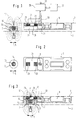
- FIG. 1 schematically shows a window or a door with a stationary frame 1, on which a wing 3 is mounted so that it can pivot about a horizontal and / or a vertical pivot axis.
- the wing 3 is movable about this pivot axis between an open position and a closed position closing the frame opening.
- a drive rod fitting In a peripheral area of the wing 3 is a drive rod fitting, not shown, for example a tilt and turn fitting in the direction of an arrow 5, ie in the circumferential direction of the wing 3, guided.
- a motor drive or a conventional handle olive or the like can be provided for actuating the connecting rod fitting.
- a locking pin 7 is fastened to the connecting rod fitting and can be moved back and forth together with the connecting rod fitting in the direction of arrow 5.
- the bolt pin 7 is assigned a bolt engagement element 9 (striking plate element) which is fixed to the frame 1 and has a bolt engagement recess 11 which is open on one side to the peripheral surface of the wing 3 and in the circumferential direction.
- the locking pin 7 can between the unlocked position shown in FIGS. 1 and 2, in which it is located outside the locking engagement recess 11, and a locked position shown in FIG. 3, in which it is in the locking engagement recess 11 is inserted and the opening movement of the wing 3 prevented, adjusted.
- the locking arrangement is conventional, and it goes without saying that the connecting rod fitting and the locking pin can also be guided on the frame 1, while the locking engagement element 9 can be arranged stationary on the wing 3.
- the locking pin 7 can also be connected in a stationary manner to the frame 1 or the sash 3, while the locking engagement element 9 can be guided to be movable in the circumferential direction on the other part of the window or the door.
- a permanent magnet 15 is fastened in a recess 13 in the locking pin substantially flush.
- the magnetic axis of the permanent magnet 15 extends approximately perpendicular to the circumferential direction and approximately parallel to the plane of the in the illustrated embodiment Wing 3.
- a chamber 21 of the bolt engagement element consisting of non-magnetic material, which at least partially overlaps with the bolt engagement recess 11 at least partially, here essentially completely overlapping in the circumferential direction of the frame 1 and is separated from the bolt engagement recess 11 by a partition 19, and is only open to the frame 1 9 are attached at a distance in the circumferential direction of the frame 1 and thus in the direction of displacement of the locking bolt 7, two magnetic field sensors 23, for example two Hall elements.
- the magnetic field sensors 23 are arranged so that they primarily respond to the magnetic field components running in the direction of the magnetic axis of the permanent magnet 7 and each deliver an output signal that is a measure of the size of this field strength component at the location of the respective magnetic field sensor 23.
- An evaluation circuit 25 is connected to the two magnetic field sensors 23 and compares the output signal of each of the two magnetic field sensors separately with a pair of reference variables.
- the reference quantity pairs define a signal window for each of the two magnetic field sensors 23, which is dimensioned such that the output signals of each of the two magnetic field sensors 23 lie within the signal window when the locking pin 7 and then the permanent magnet 15 are located within the locking engagement recess 11, i.e. the locking arrangement properly is locked (Fig. 3). If the locking pin 7 and thus the permanent magnet 15 are located outside the locking engagement recess 11, the output signals of both magnetic field sensors 23 lie outside the respectively assigned signal window.
- the monitoring circuit 25 delivers at an output 27 a monitoring signal signaling the locking state when both magnetic field sensors 23 emit output signals lying within the signal window.
- the monitoring circuit 25 delivers a monitoring signal signaling the unlocking state if at least one of the two magnetic field sensors 23 delivers an output signal lying outside the signal window.
- the magnetic field sensors 23 are generally asymmetrical to the main magnetic axis of the permanent magnet 15, the magnetic field strength components to which they respond in the locked state are of different sizes. Accordingly, the absolute values of the signal windows and, if appropriate, their width are selected differently. In spite of the fact that only a single permanent magnet 15 is used, a high degree of security against manipulation can be achieved in this way, since the field strength values lying in both signal windows are extremely difficult to simulate.
- the two magnetic field sensors 23 lie in a common plane parallel to the circumferential direction and perpendicular to the plane of the wing 3.
- the two magnetic field sensors 23 can, however, also lie in different planes. Although the arrangement shown with measuring directions parallel to one another are preferred, the measuring directions can nevertheless be inclined to one another.
- the monitoring circuit 25 is assigned a data memory 29 in which the reference variables are stored.
- the reference variables are written into the data memory 29 in an initialization phase of the monitoring circuit 25 after the locking arrangement has been installed. In the initialization phase, the wing 3 is closed and the locking arrangement is locked by inserting the locking pin 7 into the locking engagement recess 11.
- the monitoring circuit 25 determines the reference variables on the basis of the output signals supplied by the magnetic field sensors 23 and writes them into the data memory 29.
- the reference variables can be signals directly comparable with the output signals of the magnetic field sensors 23; it goes without saying that the output signals of the magnetic field sensors may also be processed, in particular digitized, if necessary can be. Both reference values of each signal window can be defined separately and written into the data memory 29; However, it is also conceivable to only define and save a reference variable and to use this reference variable to specify the limits of the signal window during monitoring.
- the monitoring circuit 25 checks the locking state in two successive monitoring cycles. In a first monitoring cycle, the magnetic field detected by the magnetic field sensors 23 is determined exclusively by the permanent magnet 15 of the locking pin 7. In a second monitoring cycle, the monitoring circuit 25 changes the spatial distribution of the magnetic field of the permanent magnet 15 and thus the magnetic field strength components at the location of the two magnetic field sensors 23 by energizing an electromagnet 31 arranged in the vicinity of the locking engagement recess 11 monitors how this above for the case of the magnetic field provided exclusively by the permanent magnet 15. It goes without saying that the variants explained there in connection can also be used here.
- the main magnetic axis of the electromagnet 31 is inclined to the main magnetic axis of the permanent magnet 15, here perpendicular to it. It goes without saying that the electromagnet 31 may be omitted if the second monitoring cycle is to be dispensed with.
- the bolt engagement element 9, the magnetic field sensors 23 and possibly the electromagnet 31 form a common structural unit in order to facilitate assembly.
- a frame bore is also indicated at 33, through which the electrical components of the structural unit can be connected to the monitoring circuit 25.
- the monitoring circuit 25 can optionally be integrated into the structural unit; however, it can also, at least with some of its components, be part of another circuit, for example a monitoring center or the like, to which further monitoring sensors or the like, possibly also other windows or doors, can be connected.
- a change in the spatial distribution of the magnetic field at the location of the magnetic field sensors 23 can result, for example, from aging of the permanent magnet 15 or from changes in the adjustment of the wing 3 relative to the frame 1.
- the magnetic field strength components at the location of the magnetic field sensors 23 can also change to such an extent that, despite a mechanically properly locked locking arrangement, they signal an unlocked state in relation to the originally stored reference quantities or, in the unlocked state, they indicate a locked state.
- the monitoring circuit 25 comprises drift correction means, the reference values stored in the memory 29 in the event of a drift-like slow change in the size of the output signals of the magnetic field sensors 23 follow the field strength component then detected.
- a time average of the output signals of the individual magnetic field sensors 23 can be formed and the deviation of this mean value from the stored reference values can be used to identify and compensate for the drift.
- the drift correction can also be carried out in such a way that if the output signal of the individual magnetic field sensor 23 assigned to the locked state deviates from the reference variable, the reference variable is corrected in the direction of the deviation by a predetermined proportion of the deviation or by a step. The size of the change then determines the rate at which the reference size follows the deviation.
Abstract
Description
Die Erfindung betrifft eine überwachbare Verriegelungsanordnung für einen an einem Rahmen zwischen einer Öffnungsstellung und einer Schließstellung beweglich, insbesondere schwenkbeweglich gelagerten Flügel eines Fensters oder einer Türe oder dergleichen.The invention relates to a monitorable locking arrangement for a wing of a window or a door or the like which is mounted on a frame between an open position and a closed position and is pivotably movable.
Aus EP-B-0 468 514 ist es zur Überwachung sowohl des Schließzustands als auch des Verriegelungszustands eines Fensters oder einer Türe bekannt, in zumindest einem Verriegelungszapfen eines in Falzumfangsrichtung des Fenster- bzw. Türflügels bewegbaren Treibstangensystems einen Dauermagnet einzusetzen, dem im rahmenseitigen Riegeleingriffselement (Schließblech) ein Magnetfeldsensor zugeordnet ist. Der Magnetfeldsensor ist im Bereich einer Riegeleingriffsaussparung an dem Riegeleingriffselement verdeckt angeordnet und überwacht, ob der Riegelzapfen in der geschlossenen Stellung des Flügels innerhalb oder außerhalb der Riegeleingriffsaussparung gelegen ist. Der Magnetfeldsensor ist als Hall-Schalter ausgebildet, d.h. integral mit einer Schwellwertschaltung versehen, die abhängig davon, ob die erfaßte Feldstärke größer oder kleiner als eine durch die Schwellwertschaltung festgelegte Referenzgröße ist, ein Überwachungssignal liefert, das die Verriegelungsstellung oder die Entriegelungsstellung des Riegelbolzens signalisiert.From EP-B-0 468 514 it is known for monitoring both the closed state and the locked state of a window or a door to use a permanent magnet in at least one locking pin of a drive rod system which can be moved in the rebate circumferential direction of the window or door leaf, which in the frame-side latch engagement element ( Striking plate) a magnetic field sensor is assigned. The magnetic field sensor is concealed in the area of a bolt engagement recess on the bolt engagement element and monitors whether the bolt pin is located inside or outside the bolt engagement recess in the closed position of the wing. The magnetic field sensor is designed as a Hall switch, that is to say integrally provided with a threshold circuit which, depending on whether the detected field strength is greater or less than a reference variable defined by the threshold circuit, supplies a monitoring signal which signals the locking position or the unlocking position of the locking bolt.
Die Ansprechempfindlichkeit der bekannten überwachbaren Verriegelungsanordnung reicht für manche Anwendungsfälle nicht aus. Die räumliche Zuordnung des Riegelzapfens und des Riegeleingriffselements an der fertig montierten Türe läßt sich aufgrund der Fertigungstoleranzen und der Einbautoleranzen nur grob vorherbestimmten. Bei der Montage des Fensters bzw. der Türe muß nicht nur die Verriegelungsmechanik justiert werden, um einwandfreies Schließen des Flügels sicherzustellen, sondern es muß auch die aus Dauermagnet und Magnetfeldsensor bestehende Überwachungseinrichtung gesondert justiert werden. Darüber hinaus ändert sich die Justierung aufgrund der mechanischen Beanspruchung des Fensters bzw. der Türe im Betrieb. Die erforderlichen Justiermaßnahmen und die Gefahr einer Dejustierung bedingen vergleichsweise große Toleranzschwellen der Magnetfelderkennung. Darüber hinaus hat sich gezeigt, daß auch die Manipulationssicherheit nicht erhöhten Anforderungen genügt, da auch bei geöffnetem Flügel mit Hilfe eines Zusatzmagnets der geschlossene und verriegelte Zustand des Fensters bzw. der Türe simuliert werden kann. Selbst wenn durch zusätzliche Sensoren die Schließstellung des Flügels erfaßt wird, könnte bei geeigneter flacher Ausbildung des Zusatzmagnets die Verriegelungsstellung bei tatsächlich unverriegeltem Flügel simuliert werden.The responsiveness of the known monitorable locking arrangement is not sufficient for some applications. The spatial assignment of the bolt pin and the bolt engagement element on the fully assembled door can only be roughly predetermined due to the manufacturing tolerances and the installation tolerances. When installing the window or door, not only must the locking mechanism be adjusted to ensure that the sash closes properly, but the monitoring device consisting of permanent magnet and magnetic field sensor must also be adjusted separately. In addition, the adjustment changes due to the mechanical stress on the window or door during operation. The necessary adjustment measures and the risk of misalignment require comparatively large tolerance thresholds for magnetic field detection. In addition, it has been shown that the security against manipulation does not meet increased requirements, since the closed and locked state of the window or door can be simulated even with the sash open using an additional magnet. Even if the closing position of the wing is detected by additional sensors, the locking position could be simulated when the wing is actually unlocked if the auxiliary magnet is suitably flat.
Aus DE 33 33 497 C2 ist es bekannt, einem berührungslos auf die Position eines Dauermagnets ansprechenden Hall-Schalter einen Abgleichmagnet zuzuordnen, der zum Einstellen der Schaltschwelle manuell justiert werden muß. Die Unterbringung eines zusätzlichen Abgleichmagnets stößt aber bei Verriegelungsanordnungen von Fenstern oder Türen auf Platzprobleme, da der Abgleichmagnet in dem ohnehin räumlich begrenzten Rahmen untergebracht werden müßte. Auch diese Anordnung läßt sich leicht manipulieren.From
Aus DE 36 32 367 C1 ist es bei überwachbaren Verriegelungsanordnungen bekannt, am Riegelelement einerseits und am Riegeleingriffselement andererseits im Abstand voneinander mehrere Magnete unterschiedlicher Feldstärke anzuordnen, welchen gesonderte Magnetfeldsensoren zugeordnet sind. An die Magnetfeldsensoren sind gesonderte Schwellwertschaltungen angeschlossen, dessen Schwellwerte jeweils für sich auf die Feldstärken der zugeordneten Magnete abgestimmt sind. Die Vielzahl unterschiedlich starker Magnete erhöht zwar die Manipulationssicherheit, erschwert aber die Montage, da die einzelnen Schwellwertschaltungen jeweils für sich justiert werden müssen.From DE 36 32 367 C1 it is known in the case of monitorable locking arrangements, on the locking element on the one hand and on the locking engagement element on the other hand at a distance from one another to arrange a plurality of magnets of different field strengths, to which separate magnetic field sensors are assigned. Separate threshold value circuits are connected to the magnetic field sensors, the threshold values of which are individually matched to the field strengths of the assigned magnets. The large number of magnets of different strengths increases the security against manipulation, but makes assembly more difficult, since the individual threshold value circuits must be adjusted individually.
Aus DE 33 16 010 C2 ist eine Infrarot-Bewegungsmeldeanlage bekannt, bei welcher die Ansprechschwelle durch eine Driftkorrekturschaltung zeitabhängig sich ändernden Betriebsparameters nachgeführt wird.From
Es ist Aufgabe der Erfindung, eine überwachbare Verriegelungsanordnung für ein Fenster oder eine Türe oder dergleichen anzugeben, die eine erhöhte Ansprechgenauigkeit hat. Die Erfindung geht aus von einer überwachbaren Verriegelungsanordnung für einen an einem Rahmen zwischen einer Öffnungsstellung und einer Schließstellung beweglich, insbesondere schwenkbeweglich gelagerten Flügel eines Fensters oder einer Türe oder dergleichen und umfaßt:
- ein Riegelelement und ein mit einer Riegeleingriffsaussparung versehenes Riegeleingriffselement, von denen eines dieser beiden Elemente, insbesondere das Riegelelement am Flügel und ein anderes dieser beiden Elemente am Rahmen relativ zueinander beweglich anzuordnen sind, derart, daß das Riegelelement und das Riegeleingriffselement in der Schließstellung des Flügels zwischen einer Verriegelungsstellung, in der das Riegelelement in Verriegelungseingriff mit der Riegeleingriffsaussparung steht und einer Entriegelungsstellung, in der das Riegelelement eine Bewegung des Flügels zuläßt, relativ zueinander bewegbar sind,
- einen an dem Riegelelement gehaltenen Dauermagnet,
- eine im Bereich der Riegeleingriffsaussparung angeordnete, insbesondere zu einer Baueinheit mit dem Riegeleingriffselement verbundene, auf das Magnetfeld des Dauermagnets ansprechende Magnetfeldsensoranordnung, deren Ausgangssignale ein Maß für die erfaßte Magnetfeldstärke sind und
- eine abhängig von den Ausgangssignalen der Magnetfeldsensoranordnung und zumindest einer Referenzgröße ein die Verriegelungsstellung oder/und die Entriegelungsstellung signalisierendes Überwachungssignal erzeugende Überwachungsschaltung.
- a locking element and a locking engagement element provided with a locking engagement recess, of which one of these two elements, in particular the locking element on the wing and another of these two elements on the frame are to be arranged such that they can move relative to one another, such that the locking element and the locking engagement element in the closed position of the wing between a locking position in which the locking element is in locking engagement with the locking engagement recess and an unlocking position in which the locking element permits movement of the leaf can be moved relative to one another,
- a permanent magnet held on the locking element,
- a arranged in the region of the bolt engagement recess, in particular to form a unit with the bolt engagement element, responsive to the magnetic field of the permanent magnet, the output signals of which are a measure of the detected magnetic field strength and
- depending on the output signals of the magnetic field sensor arrangement and at least one reference variable, a monitoring circuit that signals the locking position and / or the unlocking position.
Die vorstehend erläuterte Aufgabe wird erfindungsgemäß dadurch gelöst, daß die Überwachungsschaltung bei in der Schließstellung sich befindendem Flügel in einer Initialisierungsphase betreibbar ist, in der sie die Referenzgröße bzw. Referenzgrößen abhängig von in der Verriegelungsstellung des Riegelelements von der Magnetfeldsensoranordnung erzeugten Ausgangssignalen festlegt und in einen Speicher einschreibt.The above-described object is achieved according to the invention in that the monitoring circuit can be operated with the leaf in the closed position in an initialization phase in which it determines the reference variable or reference variables depending on output signals generated by the magnetic field sensor arrangement in the locking position of the locking element and in a memory registers.
Bei einer solchen Anordnung entfällt die manuelle elektrische Justierung der Sensorik. Die Verriegelungsanordnung muß lediglich unter mechanischen Gesichtspunkten justiert werden, um ordnungsgemäßes Schließen und Verriegeln des Flügels sicherzustellen. Nach der mechanischen Justierung wird die Überwachungsschaltung in den Initialisierungsbetrieb geschaltet, in welchem die bei der mechanischen Justierung an der Magnetfeldsensoranordnung zufällig sich ergebende Feldstärke erfaßt und davon abhängig die Referenzgröße selbsttätig festgelegt und für den nachfolgenden Überwachungsbetrieb gespeichert wird. Da der Referenzwert abhängig von der sich im Einzelfall ergebenden Einbausituation ermittelt wird, können die Toleranzgrenzen vergleichsweise eng bemessen sein, was der Genauigkeit der Überwachung zugute kommt.With such an arrangement, the manual electrical adjustment of the sensor system is not necessary. The locking arrangement only needs to be adjusted from a mechanical point of view to ensure proper closing and locking of the leaf. After the mechanical adjustment, the monitoring circuit is switched to the initialization mode, in which the field strength that randomly results during the mechanical adjustment on the magnetic field sensor arrangement is detected and, depending on this, the reference variable is automatically determined and stored for the subsequent monitoring mode. Since the reference value is determined depending on the installation situation that arises in the individual case, the tolerance limits can be comparatively narrow, which benefits the accuracy of the monitoring.
Die Magnetfeldsensoranordnung kann im Prinzip einen einzigen Magnetfeldsensor umfassen. Die Manipulationssicherheit kann jedoch beträchtlich erhöht werden, wenn mehrere Magnetfeldsensoren vorgesehen sind, die auf das Magnetfeld an örtlich im Abstand voneinander gelegenen Stellen ansprechen, wobei die Überwachungsschaltung das Überwachungssignal abhängig von den Ausgangssignalen der einzelnen Magnetfeldsensoren und den Magnetfeldsensoren gesondert zugeordneten Referenzgrößen erzeugt. Auch hier ist vorgesehen, daß die Überwachungsschaltung in der Initialisierungsphase abhängig von den Ausgangssignalen der einzelnen Magnetfeldsensoren die den Magnetfeldsensoren zugeordneten Referenzgrößen gesondert festlegt und in den Speicher einschreibt. Abhängig von der Einbausituation wird der Dauermagnet in der Verriegelungsstellung des Riegelelements an den Magnetfeldsensoren unterschiedliche Feldstärken erzeugen, deren Größe aufgrund der räumlich sich ändernden Verteilung des Magnetfelds nicht simulierbar ist. Es genügen bereits zwei Magnetfeldsensoren, um eine in hohem Maße manipulationssichere Überwachung des Verriegelungszustands zu ermöglichen.In principle, the magnetic field sensor arrangement can comprise a single magnetic field sensor. The security against manipulation can, however, be increased considerably if several magnetic field sensors are used are provided which respond to the magnetic field at locations that are spatially spaced from one another, the monitoring circuit generating the monitoring signal as a function of the output signals of the individual magnetic field sensors and the separately assigned reference variables. It is also provided here that the monitoring circuit in the initialization phase, depending on the output signals of the individual magnetic field sensors, specifies the reference quantities assigned to the magnetic field sensors separately and writes them into the memory. Depending on the installation situation, the permanent magnet in the locking position of the locking element will generate different field strengths on the magnetic field sensors, the size of which cannot be simulated due to the spatially changing distribution of the magnetic field. Two magnetic field sensors are already sufficient to enable a highly tamper-proof monitoring of the locking status.
Die Überwachungsschaltung kann jedem Magnetfeldsensor eine einzelne Referenzgröße zuordnen, die die Feldstärke je nach der Einbausituation entweder überschreiten oder unterschreiten muß, um den Verriegelungszustand zu repräsentieren. Die Manipulationssicherheit wird jedoch erhöht, wenn die Überwachungsschaltung Paare von Referenzgrößen festlegt und das Überwachungssignal abhängig davon erzeugt wird, ob die Ausgangssignale der einzelnen Magnetfeldsensoren innerhalb oder außerhalb von durch die Referenzgrößenpaare definierten Signalfenstern liegen. Das die Verriegelungsstellung repräsentierende Überwachungssignal kann hierbei abhängig davon erzeugt werden, daß die Ausgangssignale der einzelnen Magnetfeldsensoren sämtlich innerhalb der Signalfenster liegen; dieses Überwachungssignal kann aber auch davon abhängig erzeugt werden, daß in vorbestimmter Weise das Ausgangssignal wenigstens eines der Magnetfeldsensoren innerhalb des Signalfensters und wenigstens eines der Magnetfeldsensoren außerhalb des Signalfensters liegt.The monitoring circuit can assign a single reference variable to each magnetic field sensor, which, depending on the installation situation, must either exceed or fall below the field strength in order to represent the locked state. The security against manipulation is increased, however, if the monitoring circuit specifies pairs of reference variables and the monitoring signal is generated depending on whether the output signals of the individual magnetic field sensors lie inside or outside signal windows defined by the reference quantity pairs. The monitoring signal representing the locking position can be generated depending on the fact that the output signals of the individual magnetic field sensors are all within the signal window; this monitoring signal can also be generated depending on the fact that the output signal of at least one of the magnetic field sensors lies within the signal window and at least one of the magnetic field sensors lies outside the signal window in a predetermined manner.
Durch Alterung des Dauermagnets oder auch durch Änderung der mechanischen Justierung der Verriegelungsanordnung beispielsweise aufgrund von Abnutzung des Fensters oder der Türe kann es zu einer Drift der Ausgangssignale der Magnetfeldsensoren relativ zu den gespeicherten Referenzgrößen kommen. Um daraus sich ergebende Fehlfunktionen der Überwachungsschaltung zu vermeiden, können Driftkorrekturmittel vorgesehen sein, die die im Speicher gespeicherten Referenzgrößen mit einer vorbestimmten Änderungsrate oder/und abhängig von einem zeitlichen Mittelwert der Ausgangssignale der Magnetfeldsensoranordnung einer Änderung der in der Verriegelungsstellung von der Magnetfeldsensoranordnung erfaßten Feldstärke folgen lassen. Die Überwachungsschaltung sorgt also dafür, daß die Referenzgrößen einer langsamen Drift der Ausgangssignale der Magnetfeldanordnung folgen können, was der Langzeit-Erfassungsgenauigkeit zugute kommt.Due to aging of the permanent magnet or also by changing the mechanical adjustment of the locking arrangement, for example due to wear of the window or the door, the output signals of the magnetic field sensors may drift relative to the stored reference values. In order to avoid malfunctions of the monitoring circuit resulting therefrom, drift correction means can be provided which allow the reference values stored in the memory to follow a change in the field strength detected in the locking position by the magnetic field sensor arrangement with a predetermined rate of change and / or depending on a time average of the output signals of the magnetic field sensor arrangement . The monitoring circuit thus ensures that the reference quantities can follow a slow drift of the output signals of the magnetic field arrangement, which benefits the long-term detection accuracy.
In einer bevorzugten Ausgestaltung ist vorgesehen, daß im Bereich der Magnetfeldsensoranordnung, insbesondere zu einer Baueinheit mit dieser oder/und dem Riegeleingriffselement vereinigt, ein Elektromagnet angeordnet ist, dessen Magnetfeld dem Magnetfeld des Dauermagnets räumlich überlagerbar ist und daß die Überwachungsschaltung den Elektromagnet sowohl in der Initialisierungsphase als auch für die Erzeugung des Überwachungssignals bestromt. Dieser Ausgestaltung liegt die Überlegung zugrunde, daß durch einen zusätzlichen Elektromagnet die räumliche Verteilung des Magnetfelds des Dauermagnets in vorbestimmter Weise veränderbar ist. Das in der Verriegelungsstellung meßbare Magnetfeld hängt damit nicht nur vom Magnetfeld des Dauermagnets, sondern auch von der Feldstärke des Elektromagnets ab, wodurch die Manipulationssicherheit noch weiter erhöht wird.In a preferred embodiment it is provided that an electromagnet is arranged in the area of the magnetic field sensor arrangement, in particular to form a structural unit with the latter and / or the locking engagement element, the magnetic field of which can be spatially superimposed on the magnetic field of the permanent magnet and that the monitoring circuit controls the electromagnet both in the initialization phase and also energized for the generation of the monitoring signal. This embodiment is based on the consideration that the spatial distribution of the magnetic field of the permanent magnet can be changed in a predetermined manner by an additional electromagnet. The magnetic field that can be measured in the locking position thus depends not only on the magnetic field of the permanent magnet, but also on the field strength of the electromagnet, which further increases the security against manipulation.
Zur Erhöhung der Manipulationssicherheit genügt es im Prinzip, daß der Elektromagnet während der Überwachungsphase erregt ist. Eine weitere Erhöhung der Manipulationssicherheit läßt sich jedoch erreichen, wenn die Überwachungsphase mehrere Überwachungszyklen umfaßt, von denen in zumindest einem Überwachungszyklus der Elektromagnet bestromt und in zumindest einem weiteren Überwachungszyklus nicht bestromt ist. Das die Verriegelungsstellung repräsentierende Überwachungssignal wird dann abhängig von beiden Überwachungszyklen geliefert, d.h. in beiden Überwachungszyklen müssen die Ausgangssignale der Magnetfeldsensoranordnung der Verriegelungsstellung entsprechen. Die Überwachungsschaltung legt auch hier für beide Überwachungszyklen in der Initialisierungsphase Referenzgrößen fest und speichert diese.In principle, it is sufficient to increase the security against manipulation that the electromagnet is excited during the monitoring phase. A further increase in the security against manipulation can, however, be achieved if the monitoring phase involves several monitoring cycles comprises, of which the electromagnet is energized in at least one monitoring cycle and not energized in at least one further monitoring cycle. The monitoring signal representing the locking position is then delivered as a function of both monitoring cycles, ie in both monitoring cycles the output signals of the magnetic field sensor arrangement must correspond to the locking position. The monitoring circuit also defines reference values for both monitoring cycles in the initialization phase and stores them.
Der Elektromagnet ist bevorzugt räumlich asymmetrisch zu einer Meßsymmetrieachse der Magnetfeldanordnung angeordnet. Hierdurch läßt sich eine besonders große räumliche Änderung der Magnetfeldverteilung in den beiden Überwachungszyklen erreichen.The electromagnet is preferably arranged spatially asymmetrically to an axis of measurement symmetry of the magnetic field arrangement. This allows a particularly large spatial change in the magnetic field distribution to be achieved in the two monitoring cycles.
Im folgenden soll die Erfindung anhand einer Zeichnung näher erläutert werden. Hierbei zeigt:
- Fig. 1
- eine schematische, teilweise geschnittene Darstellung einer erfindungsgemäßen Verriegelungsanordnung mit Überwachungseinrichtung, dargestellt in entriegeltem Zustand;
- Fig. 2
- eine Draufsicht auf die Verriegelungsanordnung aus Fig. 1 und
- Fig. 3
- eine teilweise geschnittene Darstellung der Verriegelungsanordnung, dargestellt im verriegelten Zustand.
- Fig. 1
- is a schematic, partially sectioned illustration of a locking arrangement according to the invention with monitoring device, shown in the unlocked state;
- Fig. 2
- a plan view of the locking arrangement of Fig. 1 and
- Fig. 3
- a partially sectioned view of the locking arrangement, shown in the locked state.
Fig. 1 zeigt schematisch dargestellt ein Fenster oder eine Türe mit einem stationären Rahmen 1, an dem um eine horizontale und/oder eine vertikale Schwenkachse schwenkbeweglich ein Flügel 3 gelagert ist. Der Flügel 3 ist um diese Schwenkachse zwischen einer Öffnungsstellung und einer die Rahmenöffnung verschließenden Schließstellung beweglich. In einer Umfangsfläche des Flügels 3 ist ein nicht näher dargestellter Treibstangenbeschlag, beispielsweise ein Drehkippbeschlag in Richtung eines Pfeils 5, d.h. in Umfangsrichtung des Flügels 3, verschiebbar geführt. Für die Betätigung des Treibstangenbeschlags kann ein motorischer Antrieb oder eine herkömmliche Griffolive oder dergleichen vorgesehen sein. An dem Treibstangenbeschlag ist ein Riegelzapfen 7 befestigt und zusammen mit dem Treibstangenbeschlag in Richtung des Pfeils 5 hin- und herbewegbar. Dem Riegelzapfen 7 ist ein stationär am Rahmen 1 befestigtes Riegeleingriffselement 9 (Schließblechelement) zugeordnet, das eine zur Umfangsfläche des Flügels 3 sowie in Umfangsrichtung einseitig offene Riegeleingriffsaussparung 11 aufweist. In der Schließstellung des Flügels 3 kann der Riegelzapfen 7 zwischen der in den Fig. 1 und 2 dargestellten entriegelten Stellung, bei welcher er sich außerhalb der Riegeleingriffsaussparung 11 befindet, und einer in Fig. 3 dargestellten verriegelten Stellung, bei welcher er in die Riegeleingriffsaussparung 11 eingeschoben ist und die Öffnungsbewegung des Flügels 3 verhindert, verstellt werden.1 schematically shows a window or a door with a
Soweit bisher erläutert, ist die Verriegelungsanordnung herkömmlich ausgebildet, und es versteht sich, daß der Treibstangenbeschlag und der Riegelzapfen auch am Rahmen 1 verschiebbar geführt sein kann, während das Riegeleingriffselement 9 stationär am Flügel 3 angeordnet sein kann. In einer weiteren Alternative kann auch der Riegelzapfen 7 stationär mit dem Rahmen 1 oder dem Flügel 3 verbunden sein, während das Riegeleingriffselement 9 in Umfangsrichtung beweglich an dem jeweils anderen Teil des Fensters bzw. der Türe geführt sein kann.As far as explained so far, the locking arrangement is conventional, and it goes without saying that the connecting rod fitting and the locking pin can also be guided on the
Um in der geschlossenen Stellung des Flügels 3 überwachen zu können, ob sich der Riegelzapfen 7 innerhalb oder außerhalb der Riegeleingriffsaussparung 11 befindet, ist in einer Aussparung 13 des Riegelzapfens 7 ein Dauermagnet 15 im wesentlichen bündig versenkt befestigt. Die magnetische Achse des Dauermagnets 15 verläuft im dargestellten Ausführungsbeispiel etwa senkrecht zur Umfangsrichtung und etwa parallel zur Ebene des Flügels 3. In einer mit der Riegeleingriffsaussparung 11 zumindest teilweise, hier im wesentlichen vollständig in Umfangsrichtung des Rahmens 1 überlappenden und von der Riegeleingriffsaussparung 11 durch eine Trennwand 19 abgesonderten, im wesentlichen nur zum Rahmen 1 hin offenen Kammer 21 des aus nicht magnetischen Material bestehenden Riegeleingriffselements 9 sind mit Abstand in Umfangsrichtung des Rahmens 1 und damit in Verschieberichtung des Riegelbolzens 7 zwei Magnetfeldsensoren 23, beispielsweise zwei Hallelement befestigt. Die Magnetfeldsensoren 23 sind so angeordnet, daß sie in erster Linie auf die in Richtung der magnetischen Achse des Dauermagnets 7 verlaufenden Magnetfeldkomponenten ansprechen und liefern jeweils ein Ausgangssignal, das ein Maß für die Größe dieser Feldstärkekomponente am Ort des jeweiligen Magnetfeldsensors 23 ist.In order to be able to monitor in the closed position of the wing 3 whether the
An die beiden Magnetfeldsensoren 23 ist eine Auswerteschaltung 25 angeschlossen, die das Ausgangssignal jedes der beiden Magnetfeldsensoren gesondert mit einem Paar von Referenzgrößen vergleicht. Die Referenzgrößenpaare definieren für jeden der beiden Magnetfeldsensoren 23 ein Signalfenster, das so bemessen ist, daß die Ausgangssignale jedes der beiden Magnetfeldsensoren 23 innerhalb des Signalfensters liegen, wenn sich der Riegelzapfen 7 und dann der Dauermagnet 15 innerhalb der Riegeleingriffsaussparung 11 befindet, die Verriegelungsanordnung also ordnungsgemäß verriegelt ist (Fig. 3). Befindet sich der Riegelzapfen 7 und damit der Dauermagnet 15 außerhalb der Riegeleingriffsaussparung 11, so liegen die Ausgangssignale beider Magnetfeldsensoren 23 außerhalb der jeweils zugeordneten Signalfenster. Die Überwachungsschaltung 25 liefert an einem Ausgang 27 ein den Verriegelungszustand signalisierendes Überwachungssignal, wenn beide Magnetfeldsensoren 23 innerhalb des Signalfensters liegende Ausgangssignale abgeben. Die Überwachungsschaltung 25 liefert ein den Entriegelungszustand signalisierendes Überwachungssignal, wenn zumindest einer der beiden Magnetfeldsensoren 23 ein außerhalb des Signalfensters liegendes Ausgangssignal liefert.An
Da die Magnetfeldsensoren 23 in aller Regel unsymmetrisch zur magnetischen Hauptachse des Dauermagnets 15 liegen, sind die Magnetfeldstärkekomponenten, auf die sie im verriegelten Zustand ansprechen, unterschiedlich groß. Dementsprechend sind auch die Absolutwerte der Signalfenster und gegebenenfalls ihre Breite unterschiedlich gewählt. Trotzdem lediglich ein einzelner Dauermagnet 15 verwendet wird, läßt sich auf diese Weise eine hohe Manipulationssicherheit erreichen, da sich die in beiden Signalfenstern liegenden Feldstärkewerte nur äußerst schwer simulieren lassen.Since the
Es versteht sich, daß gegebenenfalls auch nur ein Magnetfeldsensor oder auch mehr als zwei Magnetfeldsensoren des beschriebenen Typs vorhanden sein können. Im dargestellten Ausführungsbeispiel liegen die beiden Magnetfeldsensoren 23 in einer gemeinsamen Ebene parallel zur Umfangsrichtung und senkrecht zur Ebene des Flügels 3. Die beiden Magnetfeldsensoren 23 können aber auch in verschiedenen Ebenen liegen. Wenngleich die dargestellte Anordnungsweise mit zueinander parallelen Meßrichtungen bevorzugt sind, so können doch die Meßrichtungen zueinander geneigt sein.It goes without saying that, if appropriate, only one magnetic field sensor or also more than two magnetic field sensors of the type described can be present. In the exemplary embodiment shown, the two
Der Überwachungsschaltung 25 ist ein Datenspeicher 29 zugeordnet, in welchem die Referenzgrößen gespeichert sind. Die Referenzgrößen werden in einer Initialisierungsphase der Überwachungsschaltung 25 nach der Montage der Verriegelungsanordnung in den Datenspeicher 29 eingeschrieben. In der Initialisierungsphase wird der Flügel 3 geschlossen und die Verriegelungsanordnung durch Einschieben des Riegelzapfens 7 in die Riegeleingriffsaussparung 11 verriegelt. Die Überwachungsschaltung 25 legt anhand der dabei von den Magnetfeldsensoren 23 gelieferten Ausgangssignalen die Referenzgrößen fest und schreibt sie in den Datenspeicher 29 ein. Bei den Referenzgrößen kann es sich um unmittelbar mit den Ausgangssignalen der Magnetfeldsensoren 23 vergleichbare Signale handelt; es versteht sich, daß die Ausgangssignale der Magnetfeldsensoren gegebenenfalls auch aufbereitet, insbesondere digitalisiert werden können. Es können beide Referenzgrößen jedes Signalfensters gesondert festgelegt und in den Datenspeicher 29 eingeschrieben werden; es ist aber auch denkbar, lediglich eine Referenzgröße festzulegen und zu speichern und anhand dieser Referenzgröße im Zuge der Überwachung die Grenzen des Signalfensters vorzugeben.The
Die Anordnung wurde vorstehend anhand der Überwachung mit Hilfe von Signalfenstern erläutert, bei welchen die Ausgangssignale der Magnetfeldsensoren 23 im Verriegelungszustand beide innerhalb des Signalfensters liegen müssen. Es sind jedoch auch Ausführungsformen möglich, bei welchen das Ausgangssignal eines der beiden Magnetfeldsensoren 23 innerhalb und das Ausgangssignal des anderen der beiden Magnetfeldsensoren 23 außerhalb des Signalfensters liegen müssen, um den Verriegelungszustand zu repräsentieren. Schließlich sind auch Ausführungsformen möglich, bei welchen das Ausgangssignal eines der Magnetfeldsensoren 23 oder auch beider Magnetfeldsensoren nicht anhand eines durch Referenzgrößen definierten Signalfensters überwacht wird, sondern durch herkömmliche Schwellwertschaltungen, die den Verriegelungszustand bzw. Entriegelungszustand abhängig davon überwachen, ob die Ausgangssignale der Magnetfeldsensoren 23 kleiner oder größer als den einzelnen Magnetfeldsensoren 23 zugeordnete Schwellwerte bzw. Referenzgrößen sind.The arrangement was explained above on the basis of monitoring with the aid of signal windows, in which the output signals of the
Die Überwachungsschaltung 25 überprüft den Verriegelungszustand in zwei aufeinanderfolgenden Überwachungszyklen. In einem ersten Überwachungszyklus wird das von den Magnetfeldsensoren 23 erfaßte Magnetfeld ausschließlich durch den Dauermagnet 15 des Riegelzapfens 7 bestimmt. In einem zweiten Überwachungszyklus verändert die Überwachungsschaltung 25 durch Bestromen eines in der Nachbarschaft der Riegeleingriffsaussparung 11 angeordneten Elektromagnets 31, die räumliche Verteilung des Magnetfelds des Dauermagnets 15 und damit die Magnetfeldstärkekomponenten am Ort der beiden Magnetfeldsensoren 23. Auch im zweiten Überwachungszyklus wird die Magnetfeldstärkekomponente anhand von Referenzgrößenpaaren überwacht, wie dies vorstehend für den Fall des ausschließlich durch den Dauermagnet 15 bereitgestellten Magnetfelds erläutert wurde. Es versteht sich, daß die dort im Zusammenhang erläuterten Varianten auch hier einsetzbar sind. Um eine möglichst große Änderung der räumlichen Feldverteilung zu erreichen, ist die Hauptmagnetachse des Elektromagnets 31 zur Hauptmagnetachse des Dauermagnets 15 geneigt, hier senkrecht dazu. Es versteht sich, daß der Elektromagnet 31 gegebenenfalls entfallen kann, wenn auf den zweiten Überwachungszyklus verzichtet werden soll.The
Wie Fig. 1 zeigt, bilden das Riegeleingriffselement 9, die Magnetfeldsensoren 23 und gegebenenfalls der Elektromagnet 31 eine gemeinsame Baueinheit, um die Montage zu erleichtern. Bei 33 ist ferner eine Rahmenbohrung angedeutet, durch die hindurch die elektrischen Komponenten der Baueinheit an die Überwachungsschaltung 25 angeschlossen werden können. Die Überwachungsschaltung 25 kann gegebenenfalls mit in die Baueinheit integriert sein; sie kann aber auch, zumindest mit einem Teil ihrer Komponenten, Bestandteil einer anderen Schaltung, beispielsweise einer Überwachungszentrale oder dergleichen, sein, an die weitere Überwachungssensoren oder dergleichen, gegebenenfalls auch anderer Fenster oder Türen, angeschlossen sein können.As shown in FIG. 1, the
Im Betrieb kann sich beispielsweise durch Alterung des Dauermagnets 15 oder durch Änderungen der Justierung des Flügels 3 relativ zum Rahmen 1 eine Änderung der räumlichen Verteilung des Magnetfelds am Ort der Magnetfeldsensoren 23 ergeben. Damit können sich auch die Magnetfeldstärkekomponenten am Ort der Magnetfeldsensoren 23 so weit ändern, daß sie trotz mechanisch ordnungsgemäß verriegelter Verriegelungsanordnung bezogen auf die ursprünglich gespeicherten Referenzgrößen einen Entriegelungszustand signalisieren oder aber im entriegelten Zustand einen Verriegelungszustand bezeichnen. Um dem entgegenzuwirken, umfaßt die Überwachungsschaltung 25 Driftkorrekturmittel, die die im Speicher 29 gespeicherten Referenzgrößen bei einer driftähnlichen langsamen Veränderung der Größe der Ausgangssignale der Magnetfeldsensoren 23 der dann erfaßten Feldstärkekomponente folgen lassen. Beispielsweise kann hierzu ein zeitlicher Mittelwert der Ausgangssignale der einzelnen Magnetfeldsensoren 23 gebildet werden und die Abweichung dieses Mittelwerts von den gespeicherten Referenzgrößen zum Erkennen und Ausgleichen der Drift herangezogen werden. Die Driftkorrektur kann auch in der Weise erfolgen, daß bei einer Abweichung des dem Verriegelungszustand zugeordneten Ausgangssignals des einzelnen Magnetfeldsensors 23 von der Referenzgröße die Referenzgröße um einen vorbestimmten Anteil der Abweichung oder einen Schritt vorbestimmter Größe in Richtung der Abweichung korrigiert wird. Die Größe der Änderung bestimmt dann die Rate, mit der die Referenzgröße der Abweichung folgt.In operation, a change in the spatial distribution of the magnetic field at the location of the
Claims (9)
die Überwachungsschaltung (25) bei in der Schließstellung sich befindenden Flügel (3) in einer Initialisierungsphase betreibbar ist, in der sie die Referenzgröße bzw. Referenzgrößen abhängig von in der Verriegelungsstellung des Riegelelements (7) von der Magnetfeldsensoranordnung (23) erzeugten Ausgangssignalen festlegt und in einen Speicher (29) einschreibt.A lockable monitoring arrangement for a wing (3) of a window or a door or the like, which is mounted on a frame (1) between an open position and a closed position and is pivotably movable
the monitoring circuit (25) with the leaf (3) in the closed position in an initialization phase can be operated in which it defines the reference variable or reference variables depending on output signals generated by the magnetic field sensor arrangement (23) in the locking position of the locking element (7) and writes them into a memory (29).
Applications Claiming Priority (2)
| Application Number | Priority Date | Filing Date | Title |
|---|---|---|---|
| DE19518527 | 1995-05-19 | ||
| DE1995118527 DE19518527A1 (en) | 1995-05-19 | 1995-05-19 | Monitorable locking arrangement for a window or a door or the like |
Publications (2)
| Publication Number | Publication Date |
|---|---|
| EP0743410A2 true EP0743410A2 (en) | 1996-11-20 |
| EP0743410A3 EP0743410A3 (en) | 1998-03-11 |
Family
ID=7762418
Family Applications (1)
| Application Number | Title | Priority Date | Filing Date |
|---|---|---|---|
| EP96107943A Withdrawn EP0743410A3 (en) | 1995-05-19 | 1996-05-17 | Monitored locking device for windows, doors and the like |
Country Status (2)
| Country | Link |
|---|---|
| EP (1) | EP0743410A3 (en) |
| DE (1) | DE19518527A1 (en) |
Cited By (19)
| Publication number | Priority date | Publication date | Assignee | Title |
|---|---|---|---|---|
| EP0924374A2 (en) * | 1997-12-19 | 1999-06-23 | Esco Metallbaubeschlag-Handel GmbH | Monitoring device, in particular for window or similar openable and closeable systems |
| WO2015140078A1 (en) * | 2014-03-18 | 2015-09-24 | Gretsch-Unitas GmbH Baubeschläge | Door arrangement having a motor-driven locking device |
| WO2016012520A1 (en) * | 2014-07-22 | 2016-01-28 | Mighton Products Limited | Window status sensor system |
| EP3118402A1 (en) * | 2015-07-13 | 2017-01-18 | PaX AG | Frame for a window or door |
| DE102015011299A1 (en) | 2015-09-02 | 2017-03-02 | Siegenia-Aubi Kg | Arrangement for closure monitoring |
| WO2018055398A1 (en) * | 2016-09-23 | 2018-03-29 | Giovanni Laporta | System for detecting the status of a window or door assembly |
| EP3309333A1 (en) * | 2016-10-15 | 2018-04-18 | PaX AG | Arrangement with a blind frame for storing a wing frame |
| US10027503B2 (en) * | 2013-12-11 | 2018-07-17 | Echostar Technologies International Corporation | Integrated door locking and state detection systems and methods |
| EP3342964A3 (en) * | 2016-12-29 | 2018-08-22 | SCHÜCO International KG | Frame monitoring system for windows or doors and window or door with frame monitoring system |
| US10060644B2 (en) | 2015-12-31 | 2018-08-28 | Echostar Technologies International Corporation | Methods and systems for control of home automation activity based on user preferences |
| US10073428B2 (en) | 2015-12-31 | 2018-09-11 | Echostar Technologies International Corporation | Methods and systems for control of home automation activity based on user characteristics |
| US10091017B2 (en) | 2015-12-30 | 2018-10-02 | Echostar Technologies International Corporation | Personalized home automation control based on individualized profiling |
| US10101717B2 (en) | 2015-12-15 | 2018-10-16 | Echostar Technologies International Corporation | Home automation data storage system and methods |
| US10200752B2 (en) | 2013-12-16 | 2019-02-05 | DISH Technologies L.L.C. | Methods and systems for location specific operations |
| US10294600B2 (en) | 2016-08-05 | 2019-05-21 | Echostar Technologies International Corporation | Remote detection of washer/dryer operation/fault condition |
| US10550601B2 (en) * | 2017-08-03 | 2020-02-04 | Schlage Lock Company Llc | Method and apparatus to determine a condition of a door |
| EP3539094B1 (en) | 2016-11-10 | 2020-09-23 | Delta Dore | Device and method for detecting the position of a window setting device in at least three different states |
| EP3767059A1 (en) * | 2019-07-17 | 2021-01-20 | Somfy Activites SA | Pin position detector for a hinged frame, and detection method |
| EP3828843A1 (en) * | 2019-11-28 | 2021-06-02 | dormakaba Schweiz AG | Sensor system |
Families Citing this family (14)
| Publication number | Priority date | Publication date | Assignee | Title |
|---|---|---|---|---|
| DE19815768C2 (en) * | 1998-04-08 | 2000-11-30 | Richard Ross | Tilt window lock of an object security system |
| DE19916118C2 (en) * | 1999-04-09 | 2001-03-15 | Fuss Fritz Gmbh & Co | Device for monitoring the locking of a locking device, in particular for doors and windows |
| DE10246642B4 (en) * | 2002-10-07 | 2004-12-30 | Gantner Electronic Gmbh | Electromechanical lock with protection against manipulation |
| DE102005018826B3 (en) * | 2005-04-22 | 2006-10-05 | Robert Seuffer Gmbh & Co. Kg | Closing unit e.g. window sash, position e.g. opening, detecting device, has latch whose respective position within fitting are detected with magnetic field strength of permanent magnetic field measured in two space perpendicular directions |
| DE102005046868A1 (en) * | 2005-09-30 | 2007-04-19 | Edscha Ag | Door locking device |
| DE102005000182A1 (en) | 2005-12-13 | 2007-06-21 | Aug. Winkhaus Gmbh & Co. Kg | Monitorable locking arrangement for e.g. window, has transponder that is assigned to closure bolt, and sensor cooperating with transponder and assigned to locking plate, where engagement of bolt in plate is detectable |
| DE102008017479A1 (en) | 2008-04-03 | 2009-10-15 | Moresens Gmbh | Device for magnetic position monitoring |
| DE102008001194A1 (en) | 2008-04-15 | 2009-10-22 | Aug. Winkhaus Gmbh & Co. Kg | Monitoring device of a drive rod fitting of a window |
| DE102008047194A1 (en) * | 2008-09-15 | 2010-04-15 | ABUS August Bremicker Söhne KG | Locking unit for window or door leaves |
| GB2505003A (en) * | 2012-08-18 | 2014-02-19 | Mark Gray | Fenestration alarm contact sensor for determining a locked and unlocked configuration |
| DE202014102708U1 (en) * | 2014-06-12 | 2015-09-15 | Baugruppentechnik Pollmeier Gmbh | locking system |
| DE202014009713U1 (en) | 2014-12-10 | 2015-01-30 | Kfv Karl Fliether Gmbh & Co. Kg | magnet assembly |
| DE102016107868B3 (en) | 2016-04-28 | 2017-05-11 | Insta Gmbh | Device for detecting the position of a magnet |
| DE102016123574A1 (en) | 2016-12-06 | 2018-06-07 | Maco Technologie Gmbh | safety device |
Citations (3)
| Publication number | Priority date | Publication date | Assignee | Title |
|---|---|---|---|---|
| EP0468514A1 (en) * | 1990-07-25 | 1992-01-29 | Aug. Winkhaus GmbH & Co. KG | Door or window fastener with sensor |
| DE4204509A1 (en) * | 1992-02-15 | 1993-08-19 | Merk Gmbh Telefonbau Fried | Electronic energy door surveillance for intruder alarm system - uses latch plate and contacts to provide alarm signal in response to abnormal contact operating sequence |
| EP0600795A1 (en) * | 1992-12-02 | 1994-06-08 | Jacques Lewiner | Improvements to endposition detecting devices for a bolt |
Family Cites Families (14)
| Publication number | Priority date | Publication date | Assignee | Title |
|---|---|---|---|---|
| DE2708938A1 (en) * | 1977-03-02 | 1978-09-07 | Bbc Brown Boveri & Cie | Hidden lock alarm detector - has reed relay actuated by permanent magnet field controlled by lock tongue |
| DE2813029A1 (en) * | 1978-03-23 | 1979-09-27 | Siemens Ag | Electrical monitoring system for door lock - has switching contact in guide for lock bolt incorporating magnet |
| DE3316010A1 (en) * | 1983-05-03 | 1985-01-10 | Felten & Guilleaume GmbH, 5000 Köln | Method for monitoring an essentially closed space |
| GB8322957D0 (en) * | 1983-08-26 | 1983-09-28 | Securistyle Ltd | Door/window fasteners |
| DE3333497A1 (en) * | 1983-09-16 | 1985-04-18 | Vdo Adolf Schindling Ag, 6000 Frankfurt | Position transmitter having at least one Hall switching element |
| FR2596094B1 (en) * | 1986-03-18 | 1991-12-06 | Jouan | SYSTEM FOR DETECTING IMPERFECT CLOSING OF THE DOORS OF A MULTI-DOOR ENCLOSURE |
| DE3615173A1 (en) * | 1986-05-05 | 1987-11-12 | Fuss Fritz Gmbh & Co | BLOCK LOCK |
| DE3632367C1 (en) * | 1986-09-24 | 1988-02-18 | Heinrich Saelzer | Device for remote monitoring of the position and / or movement of a shut-off device |
| DE3941086A1 (en) * | 1989-12-13 | 1991-06-20 | Daimler Benz Ag | Door cocking device with contactless state indication - uses coded strips of magnetic material in conjunction with inductive detector |
| DE9113493U1 (en) * | 1991-10-30 | 1992-01-16 | Bks Gmbh, 5620 Velbert, De | |
| IT229415Y1 (en) * | 1992-02-26 | 1998-07-02 | Conforti Spa | REMOTE CONTROL DEVICE FOR SECURITY DOORS AND SIMILAR |
| DE4318518C1 (en) * | 1993-06-03 | 1994-09-01 | Fuss Fritz Gmbh & Co | Door-monitoring device |
| DE4438168A1 (en) * | 1993-10-30 | 1995-05-04 | Aeg Sensorsysteme Gmbh | Closing device having a lock and fittings for external and internal doors |
| DE4337685C2 (en) * | 1993-11-04 | 2003-06-26 | Winkhaus Fa August | Detector retrofit kit for a locking device for a window or the like |
-
1995
- 1995-05-19 DE DE1995118527 patent/DE19518527A1/en not_active Withdrawn
-
1996
- 1996-05-17 EP EP96107943A patent/EP0743410A3/en not_active Withdrawn
Patent Citations (3)
| Publication number | Priority date | Publication date | Assignee | Title |
|---|---|---|---|---|
| EP0468514A1 (en) * | 1990-07-25 | 1992-01-29 | Aug. Winkhaus GmbH & Co. KG | Door or window fastener with sensor |
| DE4204509A1 (en) * | 1992-02-15 | 1993-08-19 | Merk Gmbh Telefonbau Fried | Electronic energy door surveillance for intruder alarm system - uses latch plate and contacts to provide alarm signal in response to abnormal contact operating sequence |
| EP0600795A1 (en) * | 1992-12-02 | 1994-06-08 | Jacques Lewiner | Improvements to endposition detecting devices for a bolt |
Cited By (26)
| Publication number | Priority date | Publication date | Assignee | Title |
|---|---|---|---|---|
| EP0924374A3 (en) * | 1997-12-19 | 2007-10-03 | Esco Metallbaubeschlag-Handel GmbH | Monitoring device, in particular for window or similar openable and closeable systems |
| EP0924374A2 (en) * | 1997-12-19 | 1999-06-23 | Esco Metallbaubeschlag-Handel GmbH | Monitoring device, in particular for window or similar openable and closeable systems |
| US10027503B2 (en) * | 2013-12-11 | 2018-07-17 | Echostar Technologies International Corporation | Integrated door locking and state detection systems and methods |
| US11109098B2 (en) | 2013-12-16 | 2021-08-31 | DISH Technologies L.L.C. | Methods and systems for location specific operations |
| US10200752B2 (en) | 2013-12-16 | 2019-02-05 | DISH Technologies L.L.C. | Methods and systems for location specific operations |
| WO2015140078A1 (en) * | 2014-03-18 | 2015-09-24 | Gretsch-Unitas GmbH Baubeschläge | Door arrangement having a motor-driven locking device |
| US10487538B2 (en) | 2014-03-18 | 2019-11-26 | Gretsch-Unitas Gmbh Baubeschlaege | Door arrangement having a motor-driven locking device |
| WO2016012520A1 (en) * | 2014-07-22 | 2016-01-28 | Mighton Products Limited | Window status sensor system |
| EP3118402A1 (en) * | 2015-07-13 | 2017-01-18 | PaX AG | Frame for a window or door |
| EP3159464A1 (en) | 2015-09-02 | 2017-04-26 | Siegenia-Aubi KG | Assembly for monitoring a closure |
| DE102015011299A1 (en) | 2015-09-02 | 2017-03-02 | Siegenia-Aubi Kg | Arrangement for closure monitoring |
| US10101717B2 (en) | 2015-12-15 | 2018-10-16 | Echostar Technologies International Corporation | Home automation data storage system and methods |
| US10091017B2 (en) | 2015-12-30 | 2018-10-02 | Echostar Technologies International Corporation | Personalized home automation control based on individualized profiling |
| US10073428B2 (en) | 2015-12-31 | 2018-09-11 | Echostar Technologies International Corporation | Methods and systems for control of home automation activity based on user characteristics |
| US10060644B2 (en) | 2015-12-31 | 2018-08-28 | Echostar Technologies International Corporation | Methods and systems for control of home automation activity based on user preferences |
| US10294600B2 (en) | 2016-08-05 | 2019-05-21 | Echostar Technologies International Corporation | Remote detection of washer/dryer operation/fault condition |
| WO2018055398A1 (en) * | 2016-09-23 | 2018-03-29 | Giovanni Laporta | System for detecting the status of a window or door assembly |
| US11473337B2 (en) | 2016-09-23 | 2022-10-18 | Giovanni Laporta | System for detecting the status of a window or door assembly |
| AU2017332835B2 (en) * | 2016-09-23 | 2023-08-17 | Giovanni Laporta | System for detecting the status of a window or door assembly |
| EP3309333A1 (en) * | 2016-10-15 | 2018-04-18 | PaX AG | Arrangement with a blind frame for storing a wing frame |
| EP3539094B1 (en) | 2016-11-10 | 2020-09-23 | Delta Dore | Device and method for detecting the position of a window setting device in at least three different states |
| EP3342964A3 (en) * | 2016-12-29 | 2018-08-22 | SCHÜCO International KG | Frame monitoring system for windows or doors and window or door with frame monitoring system |
| US10550601B2 (en) * | 2017-08-03 | 2020-02-04 | Schlage Lock Company Llc | Method and apparatus to determine a condition of a door |
| EP3767059A1 (en) * | 2019-07-17 | 2021-01-20 | Somfy Activites SA | Pin position detector for a hinged frame, and detection method |
| FR3098837A1 (en) * | 2019-07-17 | 2021-01-22 | Somfy Activites Sa | Position detector of a pin for a frame with a pivoting leaf, and detection method |
| EP3828843A1 (en) * | 2019-11-28 | 2021-06-02 | dormakaba Schweiz AG | Sensor system |
Also Published As
| Publication number | Publication date |
|---|---|
| EP0743410A3 (en) | 1998-03-11 |
| DE19518527A1 (en) | 1996-11-21 |
Similar Documents
| Publication | Publication Date | Title |
|---|---|---|
| EP0743410A2 (en) | Monitored locking device for windows, doors and the like | |
| DE102005018826B3 (en) | Closing unit e.g. window sash, position e.g. opening, detecting device, has latch whose respective position within fitting are detected with magnetic field strength of permanent magnetic field measured in two space perpendicular directions | |
| EP1862767A2 (en) | Safety positioning sensor for cylinder, cylinders with such a positioning sensor | |
| EP0468514A1 (en) | Door or window fastener with sensor | |
| DE102010018566B4 (en) | A condition detection device for a closure device and such a comprehensive closure device | |
| EP0763644B2 (en) | Window/door with locking positions between pivot/tilt frame and fixed frame | |
| WO1999043914A1 (en) | Closing device for a control cabinet door, machine casing or such like | |
| WO2009112292A1 (en) | Lock | |
| DE69926455T2 (en) | Key safety switch | |
| DE3926132C2 (en) | ||
| DE19719941C2 (en) | Electric motor-driven tilt opening device for windows, doors or the like | |
| EP3004717B1 (en) | Elevator door with a door contact switch | |
| EP3498960B1 (en) | Locking device for a door, in particular sliding door | |
| DE102008062230A1 (en) | Measuring arrangement for functional unit e.g. lock catch, of motor vehicle, has sensor detecting position of functional element from sensor signal, where stray field decreases at magnetic arrangement | |
| DE19914568A1 (en) | Magnetically actuated sensor with reed contact e.g. for detecting open state of door or window has security reed contacts for monitoring external magnetic fields | |
| DE4012253C1 (en) | Control magnet carrier - has U=shaped bin with bridge port having attachment for fixing to lock plate and two shanks | |
| DE19938378A1 (en) | Device for opening and closing an opening in a wall by means of a sliding door | |
| DE10333537A1 (en) | Circuit breaker with an electronic programmable system | |
| DE4031348A1 (en) | Security switch for protective doors - has switch with apertures fully rotatable about switch axis | |
| EP1260657B1 (en) | Lock arrangement | |
| DE202013005835U1 (en) | Closing device for doors, windows or the like | |
| EP3670794B1 (en) | Door assembly and method for operating a door assembly | |
| DE3111347A1 (en) | Pairing of locking, catching or setting elements on windows, doors or the like | |
| EP0135805B1 (en) | Door lock | |
| DE19648147C1 (en) | Motorized tilt opening device for windows or doors |
Legal Events
| Date | Code | Title | Description |
|---|---|---|---|
| PUAI | Public reference made under article 153(3) epc to a published international application that has entered the european phase |
Free format text: ORIGINAL CODE: 0009012 |
|
| AK | Designated contracting states |
Kind code of ref document: A2 Designated state(s): AT BE CH DE DK ES FI FR GB IT LI NL SE |
|
| PUAL | Search report despatched |
Free format text: ORIGINAL CODE: 0009013 |
|
| AK | Designated contracting states |
Kind code of ref document: A3 Designated state(s): AT BE CH DE DK ES FI FR GB IT LI NL SE |
|
| 17P | Request for examination filed |
Effective date: 19980515 |
|
| STAA | Information on the status of an ep patent application or granted ep patent |
Free format text: STATUS: THE APPLICATION HAS BEEN WITHDRAWN |
|
| 18W | Application withdrawn |
Withdrawal date: 19990813 |