EP0743108A1 - Method and apparatus for delivering rolled rod to a cooling bed - Google Patents
Method and apparatus for delivering rolled rod to a cooling bed Download PDFInfo
- Publication number
- EP0743108A1 EP0743108A1 EP95106982A EP95106982A EP0743108A1 EP 0743108 A1 EP0743108 A1 EP 0743108A1 EP 95106982 A EP95106982 A EP 95106982A EP 95106982 A EP95106982 A EP 95106982A EP 0743108 A1 EP0743108 A1 EP 0743108A1
- Authority
- EP
- European Patent Office
- Prior art keywords
- rod
- rollers
- run
- rolled rod
- rolled
- Prior art date
- Legal status (The legal status is an assumption and is not a legal conclusion. Google has not performed a legal analysis and makes no representation as to the accuracy of the status listed.)
- Granted
Links
Images

Classifications
-
- B—PERFORMING OPERATIONS; TRANSPORTING
- B21—MECHANICAL METAL-WORKING WITHOUT ESSENTIALLY REMOVING MATERIAL; PUNCHING METAL
- B21B—ROLLING OF METAL
- B21B43/00—Cooling beds, whether stationary or moving; Means specially associated with cooling beds, e.g. for braking work or for transferring it to or from the bed
- B21B43/003—Transfer to bed
-
- B—PERFORMING OPERATIONS; TRANSPORTING
- B21—MECHANICAL METAL-WORKING WITHOUT ESSENTIALLY REMOVING MATERIAL; PUNCHING METAL
- B21B—ROLLING OF METAL
- B21B39/00—Arrangements for moving, supporting, or positioning work, or controlling its movement, combined with or arranged in, or specially adapted for use in connection with, metal-rolling mills
- B21B39/008—Rollers for roller conveyors
-
- B—PERFORMING OPERATIONS; TRANSPORTING
- B21—MECHANICAL METAL-WORKING WITHOUT ESSENTIALLY REMOVING MATERIAL; PUNCHING METAL
- B21B—ROLLING OF METAL
- B21B39/00—Arrangements for moving, supporting, or positioning work, or controlling its movement, combined with or arranged in, or specially adapted for use in connection with, metal-rolling mills
- B21B39/02—Feeding or supporting work; Braking or tensioning arrangements, e.g. threading arrangements
- B21B39/08—Braking or tensioning arrangements
Definitions
- the invention relates to a method and apparatus for delivering longitudinally advancing straight lengths of rolled rod to a cooling bed and particularly to a method and apparatus which avoids the production of cobbles in the rolled rod.
- the invention relates particularly to such method and apparatus for handling longitudinally advancing straight lengths of rolled rod produced in a rolling mill at high speed.
- a run-in table receives the bars at high speed and the run-in table should theoretically be as smooth as possible to avoid contact of the front end of the bar with any protruding parts causing a cobble.
- the run-in table has to perform and a smooth uninterrupted surface is not possible.
- a steel bar entering the run-in table of the cooling bed at a high speed would require a very long distance for the bar to slow down before it can be discharged onto the cooling bed for cooling purposes. Such long distances require much space and unnecessary expense in the construction of a building to accommodate the extra space.
- the braking distance is proportional to the square of the finishing speed in the case of natural braking. In order to reduce this braking distance, external brakes are employed.
- An object of the invention is to provide a method and apparatus which minimizes the "bouncing effect" on the bars.
- a further object of the invention is to achieve the above without the use of pinch rollers.
- a first magnetic means is operatively associated with the lifting apron for applying braking force to a tail end of the rolled rod to reduce the speed of advance of the rolled rod and a second magnetic means is operatively associated with the run-in table in spaced downstream location from the first magnetic means for applying a pulling force to a leading end of the rolled rod to maintain the leading end of the rod in contact with the run-in table as the rod is advanced thereon.
- a plurality of longitudinally spaced rollers extend transversely of the run-in table and the lifting apron in an arrangement in which the rolled rod advanced to the run-in table rides on said rollers and said rod is transferred on said rollers to said lifting apron, said second magnetic means being disposed in at least some of said rollers.
- a control means is operatively connected to the first and second magnetic means for activating the first magnetic means when braking action is to be applied to the advancing rolled rod and for activating the second magnetic means when the rolled rod is on the run-in table.
- Each roller with the included second magnetic means therein comprises a hollow roller member, a hollow rotatable outer shaft supporting the hollow roller member for rotation therewith, a fixed inner shaft rotatably supported within the rotatable outer shaft and an electromagnetic coil fixed to said inner shaft and disposed in said hollow roller member.
- the inner shaft is hollow and the second magnetic means further comprises electrical leads in the inner shaft connected to the electromagnetic coil.
- the hollow inner shaft may include means for conveying a cooling fluid to the electromagnetic coil.
- the hollow roller member may include a detachable portion for exposing the electromagnetic coil.
- Fig. 1 is a diagrammatic longitudinal view of a conventional arrangement of a run-in table.
- Fig. 2 is a diagrammatic longitudinal view of another conventional arrangement of a run-in table.
- Fig. 3 is a diagrammatic longitudinal view of a run-in table, including one embodiment of the present invention.
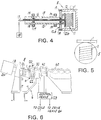
- Fig. 4 is an enlarged sectional view of a detail of a roller of the run-in table in Fig. 3.
- Fig. 5 is an end view of the roller of Fig. 4.
- Fig. 6 is a diagrammatic transverse view of the run-in table of Fig. 3 with a lifting apron and cooling bed.
- a continuous length of steel rod is fed to flying shears 3 at relatively high speed from a rolling apparatus incorporating, for example, the NTA method as disclosed in my earlier patent 5,027,632.
- the flying shears 3 cut the continuous length of rod into sections 1 which are fed to a run-in table 6 shown in Fig. 6.
- the run-in table is of double lift apron type and it operates to deliver rod sections 1 to the rakes of a cooling bed 60.
- the run-in table 6 comprises a plurality of longitudinally spaced rollers 5 rotatably supported by a fixed frame 7 at an inlet end 8 of the run-in table and at a downstream end 9 thereof.
- the rod sections 1 coming from the flying shears 3 enter the run-in table by riding on the surfaces of the rollers 5.
- Between the rollers 5 are arms 10 integral with frame 7.
- the upper surfaces of the rollers 5 are disposed slightly higher than arms 10 to insure that the rod sections 1 ride on the rollers 5.
- a lifting apron 20 is laterally adjacent to the arms 10 of the run-in table 6.
- the lifting apron 20 includes a plurality of fingers 21 which can be displaced vertically by a suitable drive mechanism (not shown) between a lowered position shown in dotted outline in Fig.
- Electromagnetic coils 22 are disposed beneath fingers 21 and form the electromagnetic pads 4.
- rollers 5 Disposed at the downstream end 9 of the run-in table 6 are the rollers 5, arms 10 and fingers 21 of the lifting apron. No electromagnetic coils 22 are provided at the downstream end. Between the upstream and downstream ends of the table 6 is an intermediate section where rollers 5 are present.
- the length of the run-in table and the number of rollers 5 is generally a function of the size of the rod sections and their speed of travel as is well known in the art.
- the rollers 5 at the downstream end 9 of the run-in table 6 include electromagnetic coils 11 therein.
- the rollers 5 comprise hollow cylindrical bodies 12 fixed to a hollow rotatable shaft 13 mounted in bearings 14.
- a smaller hollow shaft 15 is concentrically mounted in shaft 13 through the intermediary of bearings 16 between shafts 13 and 15.
- the inner shaft 15 and coil 11 are stationary.
- Electrical cables 17 pass through the interior of shaft 15 and are connected to coil 11.
- a source of cooling liquid 18 is also connected to the interior of shaft 15 to cool the electromagnetic 11.
- the cylindrical body 12 of the roller 5 includes a flange 12a fixed to shaft 13 and a detachable cylindrical portion 12b connected to flange 12a by bolts 19.
- the electromagnetic coils 11 and 22 and the lifting apron 20 are connected to a control means 23 in the form of a CPU for activating and deactivating the coils 11 and 22 and raising and lowering the lifting apron 20 in sequence to carry out the following operation.
- the continuous rod is supplied at relatively high speed to the flying shears 3.
- the apron 20 is in its raised position as shown in Fig. 6 and the rod rides on the surfaces of rollers 5 at the inlet end 8 of the run-in table.
- the raised apron 20 keeps the rod in alignment in the rolls of the flying shears approximately at the middle of the rollers 5.
- the electromagnetic coils 11 are activated to apply a pulling force on the rod to keep the head end of the rod on the rollers 5 and prevent bouncing of the head end of the rod on the rollers 5.
- the flying shears 3 then cut the rod to separate rod section 1 from the rest of the rod stock.
- the rollers 5 are then driven in rotation by a drive means 24 to accelerate the separated rod section 1 to space the cut end of the rod section from the adjacent end of the rod stock.
- the lifting apron 20 is then lowered, electromagnetic coils 11 are deenergized, the drive of rollers 5 is halted and the rod section 1 rolls downwardly by gravity on rollers 5 until the rod section contacts a fixed flange 30 extending lengthwise along the frame 7 of the run-in table.
- the electromagnetic coils 22 of the electromagnetic pads are energized to apply braking force to the tail end of the rod section 1.
- the lifting apron 20 When the rod section has slowed sufficiently, the lifting apron 20 is raised to its initial position and the rod section 1 is transferred onto the top of flange 30 where the rod rolls laterally downwards thereon to a second lifting apron 40 which is in a raised position to retain the rod section 1 on flange 30. Lifting apron 40 is subsequently lowered and the rod section 1 rolls laterally downwards thereon to abut against the rakes of the cooling bed 60. When the lifting apron 40 is subsequently raised, the rod section 1 is transferred to the top of the rakes of the cooling bed 60 and the rod is advanced stepwise on the rakes of the bed while undergoing cooling.
- the run-in table has been disclosed with reference to a two stage lifting apron which assists in slowing down the advancing rod section before it is transferred to the cooling bed.
- the invention is equally applicable to a one stage lifting apron.
- the control means 23 activates the electromagnetic coils 11 when the leading end of the rod section 1 enters the downstream section 9 to apply the pulling force on the free leading end of the rod section.
- the coils 11 are deactivated when lifting apron 20 is lowered so as not to impede the downward rolling travel of the rod section 1 on the fingers 21 of the lifting apron 20.
- the electromagnetic coils 22 are activated to apply braking force to the trailing end of the rod section, the leading end of the rod section will have been stabilized against bouncing.
- the coils 22 are deenergized so as not to impede the lifting of the rod section 1 from the rollers 5.
- the rollers 5 at the downstream section 9 are present in a number which is a function of the length of the cooling bed, the spacing of the rollers being about 1.5 meters.
- the downward pulling force exerted by the electromagnetic coils 11 in rollers 5 is relatively low and is intended to stabilize the front end of the rod section 1 without applying too great a force which would lift the trailing end of the rod section off the rollers 5.
- the braking force exerted by the electromagnetic coils 11 is much greater as the leading end of the advancing rod section tends to move downwards against the rollers when the braking force is applied. Hence, the rod remains stable on the rollers 5 without bouncing.
Landscapes
- Engineering & Computer Science (AREA)
- Mechanical Engineering (AREA)
- Heat Treatments In General, Especially Conveying And Cooling (AREA)
- Heat Treatment Of Strip Materials And Filament Materials (AREA)
- Metal Rolling (AREA)
- Rollers For Roller Conveyors For Transfer (AREA)
Abstract
Description
- The invention relates to a method and apparatus for delivering longitudinally advancing straight lengths of rolled rod to a cooling bed and particularly to a method and apparatus which avoids the production of cobbles in the rolled rod.
- The invention relates particularly to such method and apparatus for handling longitudinally advancing straight lengths of rolled rod produced in a rolling mill at high speed.
- In the past decade many developments have been made in the high speed finishing of wire rod production. Among these are the introduction of the no twist rod block and the development of "laying reel" coil forming heads. The combination of both of these techniques have increased the finishing speeds of rod rolling from 50 M/s to over 100 M/s. Relatively little development has been made on the rolling of straight bars. This is because there is not much problem with the rolling of larger bars, for example, up to 12 mm diameter. However, for diameters of 10 mm down to 8 mm, the rolling mill has to operate at lower speeds and hence at reduced capacity. In my earlier patent 5,027,632, there is disclosed a method and apparatus for rolling a bar and feeding the rolled bar to a splitter without twisting the bar (the so-called NTA system). The NTA system substantially increases the finishing speeds, but other problems still exist when a smaller diameter bar is fed to the cooling bed at a high speed.
- Essentially, a run-in table receives the bars at high speed and the run-in table should theoretically be as smooth as possible to avoid contact of the front end of the bar with any protruding parts causing a cobble. Unfortunately, there are other functions that the run-in table has to perform and a smooth uninterrupted surface is not possible. Systems requiring limitation on the maximum length of the installation of a closed channel system pose additional maintenance difficulties.
- A steel bar entering the run-in table of the cooling bed at a high speed would require a very long distance for the bar to slow down before it can be discharged onto the cooling bed for cooling purposes. Such long distances require much space and unnecessary expense in the construction of a building to accommodate the extra space. The braking distance is proportional to the square of the finishing speed in the case of natural braking. In order to reduce this braking distance, external brakes are employed.
- Two known methods for braking the bars are as follows:
- 1) Braking by pinch rollers, (Fig. 1) whereby the steel bar 1 is passed through a pair of pinch rollers 2. The pinch rollers 2 serve two purposes, first, the pinch rollers accelerate the bar that has been cut to cooling bed length by flying shears 3 to separate it from the incoming bar and second the pinch rollers 2 are driven in reverse direction to brake the steel bar 1 to a manageable speed before discharge onto rakes of the cooling bed. This method has the disadvantage that it may cause damage to the surface of the steel bar. With this system, it is not required to install additional rollers along the run-in table of the cooling bed.
- 2) Braking by magnetic pads (Fig. 2) wherein
magnetic pads 4 are installed under the lifting aprons of the run-in table. Upon energizing of themagnetic pads 4, the friction between the steel bar and the lifting table surface is increased thereby slowing the bar down. With this arrangement,additional rollers 5 are required along the lifting apron in order to accelerate the cut portion of the steel bar to separate the incoming bars after the flying shears 3. The top surfaces ofrollers 5 must protrude above the level of the lifting apron in order to have contact with the steel bars. This can cause a "bouncing effect" on the front end of the steel bars, when the front end of the bar hits the top surface of the rollers. This may be a potential hazard for producing cobbles in the cooling bed. - An object of the invention is to provide a method and apparatus which minimizes the "bouncing effect" on the bars.
- A further object of the invention is to achieve the above without the use of pinch rollers.
- The above and further objects of the invention are satisfied by a construction in which a first magnetic means is operatively associated with the lifting apron for applying braking force to a tail end of the rolled rod to reduce the speed of advance of the rolled rod and a second magnetic means is operatively associated with the run-in table in spaced downstream location from the first magnetic means for applying a pulling force to a leading end of the rolled rod to maintain the leading end of the rod in contact with the run-in table as the rod is advanced thereon.
- In accordance with the invention, a plurality of longitudinally spaced rollers extend transversely of the run-in table and the lifting apron in an arrangement in which the rolled rod advanced to the run-in table rides on said rollers and said rod is transferred on said rollers to said lifting apron, said second magnetic means being disposed in at least some of said rollers.
- In further accordance with the invention, a control means is operatively connected to the first and second magnetic means for activating the first magnetic means when braking action is to be applied to the advancing rolled rod and for activating the second magnetic means when the rolled rod is on the run-in table.
- Each roller with the included second magnetic means therein comprises a hollow roller member, a hollow rotatable outer shaft supporting the hollow roller member for rotation therewith, a fixed inner shaft rotatably supported within the rotatable outer shaft and an electromagnetic coil fixed to said inner shaft and disposed in said hollow roller member. According to a feature of the invention, the inner shaft is hollow and the second magnetic means further comprises electrical leads in the inner shaft connected to the electromagnetic coil. Additionally, the hollow inner shaft may include means for conveying a cooling fluid to the electromagnetic coil. Furthermore, the hollow roller member may include a detachable portion for exposing the electromagnetic coil.
- Fig. 1 is a diagrammatic longitudinal view of a conventional arrangement of a run-in table.
- Fig. 2 is a diagrammatic longitudinal view of another conventional arrangement of a run-in table.
- Fig. 3 is a diagrammatic longitudinal view of a run-in table, including one embodiment of the present invention.
- Fig. 4 is an enlarged sectional view of a detail of a roller of the run-in table in Fig. 3.
- Fig. 5 is an end view of the roller of Fig. 4.
- Fig. 6 is a diagrammatic transverse view of the run-in table of Fig. 3 with a lifting apron and cooling bed.
- Referring to Fig. 3, a continuous length of steel rod is fed to flying shears 3 at relatively high speed from a rolling apparatus incorporating, for example, the NTA method as disclosed in my earlier patent 5,027,632. The flying shears 3 cut the continuous length of rod into sections 1 which are fed to a run-in table 6 shown in Fig. 6. The run-in table is of double lift apron type and it operates to deliver rod sections 1 to the rakes of a
cooling bed 60. - The run-in table 6 comprises a plurality of longitudinally spaced
rollers 5 rotatably supported by a fixed frame 7 at an inlet end 8 of the run-in table and at adownstream end 9 thereof. The rod sections 1 coming from the flying shears 3 enter the run-in table by riding on the surfaces of therollers 5. Between therollers 5 are arms 10 integral with frame 7. The upper surfaces of therollers 5 are disposed slightly higher than arms 10 to insure that the rod sections 1 ride on therollers 5. A liftingapron 20 is laterally adjacent to the arms 10 of the run-in table 6. Thelifting apron 20 includes a plurality offingers 21 which can be displaced vertically by a suitable drive mechanism (not shown) between a lowered position shown in dotted outline in Fig. 6 and a raised position shown in solid lines in Fig. 6. In the lowered position, the upper surface of thefingers 21 are aligned with the upper surface of the arms 10. The surfaces of the arms 10, thefingers 21 and therollers 5 are inclined laterally downwards so that rod sections 1 can roll laterally downwards by gravity on therollers 5 as will be explained later.Electromagnetic coils 22 are disposed beneathfingers 21 and form theelectromagnetic pads 4. - Disposed at the
downstream end 9 of the run-in table 6 are therollers 5, arms 10 andfingers 21 of the lifting apron. Noelectromagnetic coils 22 are provided at the downstream end. Between the upstream and downstream ends of the table 6 is an intermediate section whererollers 5 are present. The length of the run-in table and the number ofrollers 5 is generally a function of the size of the rod sections and their speed of travel as is well known in the art. - The
rollers 5 at thedownstream end 9 of the run-in table 6 includeelectromagnetic coils 11 therein. Therollers 5 comprise hollowcylindrical bodies 12 fixed to a hollowrotatable shaft 13 mounted inbearings 14. A smallerhollow shaft 15 is concentrically mounted inshaft 13 through the intermediary ofbearings 16 betweenshafts inner shaft 15 andcoil 11 are stationary.Electrical cables 17 pass through the interior ofshaft 15 and are connected tocoil 11. A source of coolingliquid 18 is also connected to the interior ofshaft 15 to cool the electromagnetic 11. In order to furnish access to the interior of theelectromagnetic coil 11 and its related components, thecylindrical body 12 of theroller 5 includes a flange 12a fixed toshaft 13 and a detachable cylindrical portion 12b connected to flange 12a by bolts 19. - The electromagnetic coils 11 and 22 and the lifting
apron 20 are connected to a control means 23 in the form of a CPU for activating and deactivating thecoils apron 20 in sequence to carry out the following operation. - The continuous rod is supplied at relatively high speed to the flying shears 3. The
apron 20 is in its raised position as shown in Fig. 6 and the rod rides on the surfaces ofrollers 5 at the inlet end 8 of the run-in table. The raisedapron 20 keeps the rod in alignment in the rolls of the flying shears approximately at the middle of therollers 5. When the leading or head end of rod l reaches therollers 5 at thedownstream end 9 of the run-in table, theelectromagnetic coils 11 are activated to apply a pulling force on the rod to keep the head end of the rod on therollers 5 and prevent bouncing of the head end of the rod on therollers 5. The flying shears 3 then cut the rod to separate rod section 1 from the rest of the rod stock. Therollers 5 are then driven in rotation by a drive means 24 to accelerate the separated rod section 1 to space the cut end of the rod section from the adjacent end of the rod stock. The liftingapron 20 is then lowered,electromagnetic coils 11 are deenergized, the drive ofrollers 5 is halted and the rod section 1 rolls downwardly by gravity onrollers 5 until the rod section contacts a fixedflange 30 extending lengthwise along the frame 7 of the run-in table. Then theelectromagnetic coils 22 of the electromagnetic pads are energized to apply braking force to the tail end of the rod section 1. When the rod section has slowed sufficiently, the liftingapron 20 is raised to its initial position and the rod section 1 is transferred onto the top offlange 30 where the rod rolls laterally downwards thereon to asecond lifting apron 40 which is in a raised position to retain the rod section 1 onflange 30. Liftingapron 40 is subsequently lowered and the rod section 1 rolls laterally downwards thereon to abut against the rakes of the coolingbed 60. When the liftingapron 40 is subsequently raised, the rod section 1 is transferred to the top of the rakes of the coolingbed 60 and the rod is advanced stepwise on the rakes of the bed while undergoing cooling. - When the lifting
apron 20 has been raised to its initial position and the rod section 1 has been transferred to the top offlange 30, the run-in table is in its initial state to receive the leading end of the rod stock to repeat the operation. - The run-in table has been disclosed with reference to a two stage lifting apron which assists in slowing down the advancing rod section before it is transferred to the cooling bed. The invention, however, is equally applicable to a one stage lifting apron.
- In the sequence of the operation, the control means 23 activates the
electromagnetic coils 11 when the leading end of the rod section 1 enters thedownstream section 9 to apply the pulling force on the free leading end of the rod section. Thecoils 11 are deactivated when liftingapron 20 is lowered so as not to impede the downward rolling travel of the rod section 1 on thefingers 21 of the liftingapron 20. When theelectromagnetic coils 22 are activated to apply braking force to the trailing end of the rod section, the leading end of the rod section will have been stabilized against bouncing. When the liftingapron 20 is ready to be raised again, thecoils 22 are deenergized so as not to impede the lifting of the rod section 1 from therollers 5. - By virtue of the action of both the
electromagnetic coils - The
rollers 5 at thedownstream section 9 are present in a number which is a function of the length of the cooling bed, the spacing of the rollers being about 1.5 meters. The downward pulling force exerted by theelectromagnetic coils 11 inrollers 5 is relatively low and is intended to stabilize the front end of the rod section 1 without applying too great a force which would lift the trailing end of the rod section off therollers 5. The braking force exerted by theelectromagnetic coils 11 is much greater as the leading end of the advancing rod section tends to move downwards against the rollers when the braking force is applied. Hence, the rod remains stable on therollers 5 without bouncing. - Although the invention has been described in relation to a specific embodiment thereof, it will become apparent to those skilled in the art that numerous modifications and variations can be made within the scope and spirit of the invention as defined in the attached claims.
Claims (10)
- Rolling mill apparatus for high speed production of rolled rod in which rolled rod is advanced to an entry end of a run-in table and after supply of the rolled rod onto the run-in table, the rod is laterally displaced onto a lifting apron for braking and subsequent transport towards a cooling bed, characterized in that first magnetic means are operatively associated with the lifting apron for applying braking force to a tail end of the rolled rod to reduce speed of advance of the rolled rod and second magnetic means are operatively associated with the run-in table in spaced downstream location from the first magnetic means for applying a pulling force to a leading end of the rolled rod to maintain the leading end of the rod in contact with the run-in table as the rod is advanced thereon.
- Apparatus as claimed in claim 1, characterized in that a plurality of longitudinally spaced rollers are provided which extend transversely of the run-in table and the lifting apron in an arrangement in which the rolled rod advanced to the run-in table rides on said rollers and said rod is transferred on said rollers to said lifting apron, said second magnetic means being disposed in at least some of the said rollers.
- Apparatus as claimed in claim 2, characterized in that said first magnetic means comprises magnetic pads disposed under the lifting apron between successive rollers in the region of the entry end of the run-in table, control means being provided for activating said first magnetic means when braking action is to be applied to the advancing rod, said second magnetic means being connected to said control means to be activated when the rolled rod is on the run-in table.
- Apparatus as claimed in claim 3, characterized in that said rollers are downwardly inclined from the run-in table to the lifting apron, said lifting apron comprising fingers between the rollers which are vertically displaceable between a lowered position in which the rolled rod travels downwardly on the rollers from the run-in table to the lifting apron, and a raised position in which the rolled rod on the lifting apron is lifted from the rollers for delivery towards the cooling bed, said control means deactivating said first and second magnetic means when the lifting apron is moved from the lowered position to the raised position.
- Apparatus as claimed in claim 2, characterized in that said rollers in which said second magnetic means are disposed, each comprises a hollow roller member, a hollow rotatable outer shaft supporting said hollow roller member for rotation therewith, a fixed inner shaft rotatably supported within the rotatable outer shaft and an electromagnetic coil fixed to said inner shaft and disposed in said hollow roller member.
- Apparatus as claimed in claim 5, characterized in that said inner shaft is hollow, said second magnetic means further comprising electrical leads in said inner shaft connected to said electromagnetic coil, said hollow inner shaft containing means for conveying a cooling fluid to said electromagnetic coil, said hollow roller member including a detachable portion for exposing said electromagnetic coil in the hollow roller member.
- A method of delivering longitudinally advancing lengths of rolled rod to a cooling bed in which the rolled rod is longitudinally advanced through a shearing means to a run-in table whereat the rod travels on the surfaces of longitudinally spaced rollers, characterized in that:a downward pulling force is applied through selected ones of said rollers at a downstream portion of the run-in table to urge a leading portion of the longitudinally advancing rolled rod against the selected rollers;said rolled rod being laterally displaced along said rollers, from said run-in table onto a lifting apron, while said rolled rod is longitudinally advancing,braking force is applied to a trailing end portion of said longitudinally advancing length of rolled rod on said lifting apron; andthereafter, the lifting apron is raised to lift the rolled rod from the rollers for transport to the cooling bed.
- A method as claimed in claim 7, characterized in that the pulling force and the braking force are deactivated when the rolled rod is lifted from the rollers.
- A method as claimed in claim 7, characterized in that said downward pulling force is applied to the leading portion of said rolled rod through said selected ones of said rollers before the braking force is applied to the trailing portion of the rolled rod and the application of downward pulling force on the rod is halted before the rod is laterally displaced onto the lifting apron.
- A method as claimed in claim 7, characterized in that the rod is cut by the shearing means when the leading end of the rolled rod is on the rollers and is being pulled down on the rollers, and the longitudinal advance of the length of rolled rod is accelerated when it is cut by the shearing means in order to space a cut tail end of the rolled rod from a head end of the remainder of the rod.
Priority Applications (5)
| Application Number | Priority Date | Filing Date | Title |
|---|---|---|---|
| AT95106982T ATE194303T1 (en) | 1995-05-09 | 1995-05-09 | METHOD AND DEVICE FOR TRANSFERRING ROLLED BARS TO A COOLING BED |
| PT95106982T PT743108E (en) | 1995-05-09 | 1995-05-09 | METHOD AND APPARATUS FOR PROVIDING LAMINATED VARIUM TO A COOLING BED |
| ES95106982T ES2149905T3 (en) | 1995-05-09 | 1995-05-09 | PROCEDURE AND DEVICE FOR CONDUCTING ROLLED RODS TO A COOLING BED. |
| EP95106982A EP0743108B1 (en) | 1995-05-09 | 1995-05-09 | Method and apparatus for delivering rolled rod to a cooling bed |
| DE69517798T DE69517798T2 (en) | 1995-05-09 | 1995-05-09 | Method and device for transferring rolled bars to a cooling bed |
Applications Claiming Priority (1)
| Application Number | Priority Date | Filing Date | Title |
|---|---|---|---|
| EP95106982A EP0743108B1 (en) | 1995-05-09 | 1995-05-09 | Method and apparatus for delivering rolled rod to a cooling bed |
Publications (2)
| Publication Number | Publication Date |
|---|---|
| EP0743108A1 true EP0743108A1 (en) | 1996-11-20 |
| EP0743108B1 EP0743108B1 (en) | 2000-07-05 |
Family
ID=8219235
Family Applications (1)
| Application Number | Title | Priority Date | Filing Date |
|---|---|---|---|
| EP95106982A Expired - Lifetime EP0743108B1 (en) | 1995-05-09 | 1995-05-09 | Method and apparatus for delivering rolled rod to a cooling bed |
Country Status (5)
| Country | Link |
|---|---|
| EP (1) | EP0743108B1 (en) |
| AT (1) | ATE194303T1 (en) |
| DE (1) | DE69517798T2 (en) |
| ES (1) | ES2149905T3 (en) |
| PT (1) | PT743108E (en) |
Cited By (5)
| Publication number | Priority date | Publication date | Assignee | Title |
|---|---|---|---|---|
| CN110102582A (en) * | 2019-05-16 | 2019-08-09 | 中冶南方工程技术有限公司 | A kind of short ruler bar automatic separating apparatus |
| CN111804742A (en) * | 2020-07-12 | 2020-10-23 | 铜陵市富鑫钢铁有限公司 | Cooling bed afterbody arresting gear on rod |
| CN113909312A (en) * | 2020-07-10 | 2022-01-11 | 北京京诚瑞信长材工程技术有限公司 | Steel feeding system of multi-segmentation cooling bed |
| CN114602975A (en) * | 2022-03-11 | 2022-06-10 | 山东钢铁集团永锋临港有限公司 | Flying shear equipment for solving problem of incapability of breaking steel pile in controlled rolling and controlled cooling bar finish rolling |
| CN117000790A (en) * | 2023-10-07 | 2023-11-07 | 陕西钢铁集团有限公司 | Head-tail separation device and method for cooling bed on steel rolling short distance |
Citations (5)
| Publication number | Priority date | Publication date | Assignee | Title |
|---|---|---|---|---|
| FR659947A (en) * | 1927-09-17 | 1929-07-04 | Schloemann Ag | Roller for transporting magnetic objects |
| EP0031105A1 (en) * | 1979-12-24 | 1981-07-01 | Sms Schloemann-Siemag Aktiengesellschaft | Device for altering the velocity of hot rolled material on roll tables of cooling beds by magnetic fields |
| DD226208A1 (en) * | 1984-07-25 | 1985-08-21 | Thaelmann Schwermaschbau Veb | METHOD AND CIRCUIT ARRANGEMENT FOR SHUT-OFF OF ROLLING GOODS |
| DD228391A1 (en) * | 1984-07-25 | 1985-10-09 | Thaelmann Schwermaschbau Veb | MAGNET BRAKE SHIFTER FOR A REVERSE ROLL BEFORE THE COOLER BED |
| US5027632A (en) * | 1990-02-02 | 1991-07-02 | Pong David T | No-twist slit-rolling approach ("NTA") apparatus and method for manufacturing steel reinforcing rod |
-
1995
- 1995-05-09 EP EP95106982A patent/EP0743108B1/en not_active Expired - Lifetime
- 1995-05-09 DE DE69517798T patent/DE69517798T2/en not_active Expired - Fee Related
- 1995-05-09 ES ES95106982T patent/ES2149905T3/en not_active Expired - Lifetime
- 1995-05-09 AT AT95106982T patent/ATE194303T1/en not_active IP Right Cessation
- 1995-05-09 PT PT95106982T patent/PT743108E/en unknown
Patent Citations (5)
| Publication number | Priority date | Publication date | Assignee | Title |
|---|---|---|---|---|
| FR659947A (en) * | 1927-09-17 | 1929-07-04 | Schloemann Ag | Roller for transporting magnetic objects |
| EP0031105A1 (en) * | 1979-12-24 | 1981-07-01 | Sms Schloemann-Siemag Aktiengesellschaft | Device for altering the velocity of hot rolled material on roll tables of cooling beds by magnetic fields |
| DD226208A1 (en) * | 1984-07-25 | 1985-08-21 | Thaelmann Schwermaschbau Veb | METHOD AND CIRCUIT ARRANGEMENT FOR SHUT-OFF OF ROLLING GOODS |
| DD228391A1 (en) * | 1984-07-25 | 1985-10-09 | Thaelmann Schwermaschbau Veb | MAGNET BRAKE SHIFTER FOR A REVERSE ROLL BEFORE THE COOLER BED |
| US5027632A (en) * | 1990-02-02 | 1991-07-02 | Pong David T | No-twist slit-rolling approach ("NTA") apparatus and method for manufacturing steel reinforcing rod |
Cited By (6)
| Publication number | Priority date | Publication date | Assignee | Title |
|---|---|---|---|---|
| CN110102582A (en) * | 2019-05-16 | 2019-08-09 | 中冶南方工程技术有限公司 | A kind of short ruler bar automatic separating apparatus |
| CN113909312A (en) * | 2020-07-10 | 2022-01-11 | 北京京诚瑞信长材工程技术有限公司 | Steel feeding system of multi-segmentation cooling bed |
| CN113909312B (en) * | 2020-07-10 | 2024-04-26 | 北京京诚瑞信长材工程技术有限公司 | Multi-splitting cooling bed steel feeding system |
| CN111804742A (en) * | 2020-07-12 | 2020-10-23 | 铜陵市富鑫钢铁有限公司 | Cooling bed afterbody arresting gear on rod |
| CN114602975A (en) * | 2022-03-11 | 2022-06-10 | 山东钢铁集团永锋临港有限公司 | Flying shear equipment for solving problem of incapability of breaking steel pile in controlled rolling and controlled cooling bar finish rolling |
| CN117000790A (en) * | 2023-10-07 | 2023-11-07 | 陕西钢铁集团有限公司 | Head-tail separation device and method for cooling bed on steel rolling short distance |
Also Published As
| Publication number | Publication date |
|---|---|
| ATE194303T1 (en) | 2000-07-15 |
| PT743108E (en) | 2000-12-29 |
| ES2149905T3 (en) | 2000-11-16 |
| EP0743108B1 (en) | 2000-07-05 |
| DE69517798T2 (en) | 2001-02-01 |
| DE69517798D1 (en) | 2000-08-10 |
Similar Documents
| Publication | Publication Date | Title |
|---|---|---|
| US5690008A (en) | Method for delivering rolled rod to a cooling bed | |
| EP1877203B2 (en) | Compact plant for continuous production of bars and/or profiles | |
| GB2129723A (en) | Manufacture of metal strip | |
| EP0795361B1 (en) | Method for the continuous rolling of plate and/or strip and the relative continuous rolling line | |
| EP0743108B1 (en) | Method and apparatus for delivering rolled rod to a cooling bed | |
| KR100563535B1 (en) | Bar delivery system and method | |
| CN1067607C (en) | Method for taking rolled thin-rod to cooling bed and apparatus thereof | |
| US3700157A (en) | Apparatus for feeding strip-like material to a processing apparatus | |
| DE2425463C2 (en) | Working method for further processing of profile steel following a fine steel rolling mill and arrangement for carrying out the method | |
| US5921127A (en) | Hot strip rolling mill | |
| JPH09225529A (en) | Method and device for operation of strip plate coiling machine | |
| CN1053397C (en) | Rolling mill material handling system | |
| AU696859B2 (en) | Method and apparatus for delivering rolled rod to a cooling bed | |
| KR100363404B1 (en) | High speed rolling equipment and delivery method for rolling rod | |
| JPH0648562A (en) | Device for transportation of rolled material which is wound around ring in reeling area | |
| US3422649A (en) | Automatic threading device for rolling mills | |
| JP2832585B2 (en) | Method and apparatus for sending a rolling rod to a cooling floor | |
| CN201832928U (en) | Device for winding copper pipe coil | |
| EP1670601B1 (en) | System for contactless application of tension in electrically conductive metal strips | |
| JPS59110415A (en) | Transfer roller table in front of cooling floor for transferring continuously carried standard size rolling material | |
| JP2530409B2 (en) | Conveyance level adjustment method in steel pipe longitudinal feed conveyor | |
| JP2820520B2 (en) | Switching method of winder in endless hot rolling | |
| JPS6247089B2 (en) | ||
| EP0701873B1 (en) | Intermediate storage oven downstream of a thin stab casting plant | |
| SU975131A1 (en) | Method of controlling speed duty of run-out rolling table |
Legal Events
| Date | Code | Title | Description |
|---|---|---|---|
| PUAI | Public reference made under article 153(3) epc to a published international application that has entered the european phase |
Free format text: ORIGINAL CODE: 0009012 |
|
| AK | Designated contracting states |
Kind code of ref document: A1 Designated state(s): AT BE CH DE DK ES FR GB GR IE IT LI LU MC NL PT SE |
|
| AX | Request for extension of the european patent |
Free format text: LT PAYMENT 950608;SI PAYMENT 950608 |
|
| RAX | Requested extension states of the european patent have changed |
Free format text: LT PAYMENT 950608;SI PAYMENT 950608 |
|
| 17P | Request for examination filed |
Effective date: 19970317 |
|
| R17P | Request for examination filed (corrected) |
Effective date: 19970317 |
|
| 17Q | First examination report despatched |
Effective date: 19981007 |
|
| GRAG | Despatch of communication of intention to grant |
Free format text: ORIGINAL CODE: EPIDOS AGRA |
|
| GRAG | Despatch of communication of intention to grant |
Free format text: ORIGINAL CODE: EPIDOS AGRA |
|
| GRAH | Despatch of communication of intention to grant a patent |
Free format text: ORIGINAL CODE: EPIDOS IGRA |
|
| GRAH | Despatch of communication of intention to grant a patent |
Free format text: ORIGINAL CODE: EPIDOS IGRA |
|
| GRAA | (expected) grant |
Free format text: ORIGINAL CODE: 0009210 |
|
| AK | Designated contracting states |
Kind code of ref document: B1 Designated state(s): AT BE CH DE DK ES FR GB GR IE IT LI LU MC NL PT SE |
|
| AX | Request for extension of the european patent |
Free format text: LT PAYMENT 19950608;SI PAYMENT 19950608 |
|
| LTIE | Lt: invalidation of european patent or patent extension | ||
| REF | Corresponds to: |
Ref document number: 194303 Country of ref document: AT Date of ref document: 20000715 Kind code of ref document: T |
|
| REG | Reference to a national code |
Ref country code: CH Ref legal event code: EP |
|
| REG | Reference to a national code |
Ref country code: IE Ref legal event code: FG4D |
|
| REF | Corresponds to: |
Ref document number: 69517798 Country of ref document: DE Date of ref document: 20000810 |
|
| ITF | It: translation for a ep patent filed |
Owner name: BARZANO' E ZANARDO ROMA S.P.A. |
|
| PG25 | Lapsed in a contracting state [announced via postgrant information from national office to epo] |
Ref country code: DK Free format text: LAPSE BECAUSE OF FAILURE TO SUBMIT A TRANSLATION OF THE DESCRIPTION OR TO PAY THE FEE WITHIN THE PRESCRIBED TIME-LIMIT Effective date: 20001005 |
|
| ET | Fr: translation filed | ||
| REG | Reference to a national code |
Ref country code: ES Ref legal event code: FG2A Ref document number: 2149905 Country of ref document: ES Kind code of ref document: T3 |
|
| REG | Reference to a national code |
Ref country code: CH Ref legal event code: NV Representative=s name: A. BRAUN, BRAUN, HERITIER, ESCHMANN AG PATENTANWAE |
|
| REG | Reference to a national code |
Ref country code: PT Ref legal event code: SC4A Free format text: AVAILABILITY OF NATIONAL TRANSLATION Effective date: 20000921 |
|
| PLBE | No opposition filed within time limit |
Free format text: ORIGINAL CODE: 0009261 |
|
| STAA | Information on the status of an ep patent application or granted ep patent |
Free format text: STATUS: NO OPPOSITION FILED WITHIN TIME LIMIT |
|
| PG25 | Lapsed in a contracting state [announced via postgrant information from national office to epo] |
Ref country code: IE Free format text: LAPSE BECAUSE OF NON-PAYMENT OF DUE FEES Effective date: 20010509 |
|
| PG25 | Lapsed in a contracting state [announced via postgrant information from national office to epo] |
Ref country code: MC Free format text: LAPSE BECAUSE OF NON-PAYMENT OF DUE FEES Effective date: 20010531 |
|
| 26N | No opposition filed | ||
| REG | Reference to a national code |
Ref country code: GB Ref legal event code: IF02 |
|
| REG | Reference to a national code |
Ref country code: IE Ref legal event code: MM4A |
|
| PGFP | Annual fee paid to national office [announced via postgrant information from national office to epo] |
Ref country code: CH Payment date: 20020422 Year of fee payment: 8 |
|
| PGFP | Annual fee paid to national office [announced via postgrant information from national office to epo] |
Ref country code: NL Payment date: 20020423 Year of fee payment: 8 |
|
| PGFP | Annual fee paid to national office [announced via postgrant information from national office to epo] |
Ref country code: AT Payment date: 20020426 Year of fee payment: 8 |
|
| PGFP | Annual fee paid to national office [announced via postgrant information from national office to epo] |
Ref country code: LU Payment date: 20020502 Year of fee payment: 8 |
|
| PGFP | Annual fee paid to national office [announced via postgrant information from national office to epo] |
Ref country code: BE Payment date: 20020521 Year of fee payment: 8 |
|
| PG25 | Lapsed in a contracting state [announced via postgrant information from national office to epo] |
Ref country code: LU Free format text: LAPSE BECAUSE OF NON-PAYMENT OF DUE FEES Effective date: 20030509 Ref country code: AT Free format text: LAPSE BECAUSE OF NON-PAYMENT OF DUE FEES Effective date: 20030509 |
|
| PG25 | Lapsed in a contracting state [announced via postgrant information from national office to epo] |
Ref country code: LI Free format text: LAPSE BECAUSE OF NON-PAYMENT OF DUE FEES Effective date: 20030531 Ref country code: CH Free format text: LAPSE BECAUSE OF NON-PAYMENT OF DUE FEES Effective date: 20030531 Ref country code: BE Free format text: LAPSE BECAUSE OF NON-PAYMENT OF DUE FEES Effective date: 20030531 |
|
| BERE | Be: lapsed |
Owner name: *PONG DAVID TENG Effective date: 20030531 |
|
| PG25 | Lapsed in a contracting state [announced via postgrant information from national office to epo] |
Ref country code: NL Free format text: LAPSE BECAUSE OF NON-PAYMENT OF DUE FEES Effective date: 20031201 |
|
| REG | Reference to a national code |
Ref country code: CH Ref legal event code: PL |
|
| NLV4 | Nl: lapsed or anulled due to non-payment of the annual fee |
Effective date: 20031201 |
|
| PGFP | Annual fee paid to national office [announced via postgrant information from national office to epo] |
Ref country code: PT Payment date: 20050408 Year of fee payment: 11 Ref country code: GB Payment date: 20050408 Year of fee payment: 11 |
|
| PGFP | Annual fee paid to national office [announced via postgrant information from national office to epo] |
Ref country code: FR Payment date: 20050420 Year of fee payment: 11 |
|
| PGFP | Annual fee paid to national office [announced via postgrant information from national office to epo] |
Ref country code: DE Payment date: 20050421 Year of fee payment: 11 |
|
| PGFP | Annual fee paid to national office [announced via postgrant information from national office to epo] |
Ref country code: GR Payment date: 20050427 Year of fee payment: 11 |
|
| PGFP | Annual fee paid to national office [announced via postgrant information from national office to epo] |
Ref country code: ES Payment date: 20050504 Year of fee payment: 11 |
|
| PG25 | Lapsed in a contracting state [announced via postgrant information from national office to epo] |
Ref country code: GB Free format text: LAPSE BECAUSE OF NON-PAYMENT OF DUE FEES Effective date: 20060509 |
|
| PG25 | Lapsed in a contracting state [announced via postgrant information from national office to epo] |
Ref country code: ES Free format text: LAPSE BECAUSE OF NON-PAYMENT OF DUE FEES Effective date: 20060510 |
|
| PGFP | Annual fee paid to national office [announced via postgrant information from national office to epo] |
Ref country code: IT Payment date: 20060531 Year of fee payment: 12 |
|
| PG25 | Lapsed in a contracting state [announced via postgrant information from national office to epo] |
Ref country code: PT Free format text: LAPSE BECAUSE OF NON-PAYMENT OF DUE FEES Effective date: 20061109 |
|
| PG25 | Lapsed in a contracting state [announced via postgrant information from national office to epo] |
Ref country code: DE Free format text: LAPSE BECAUSE OF NON-PAYMENT OF DUE FEES Effective date: 20061201 |
|
| REG | Reference to a national code |
Ref country code: PT Ref legal event code: MM4A Free format text: LAPSE DUE TO NON-PAYMENT OF FEES Effective date: 20061109 |
|
| GBPC | Gb: european patent ceased through non-payment of renewal fee |
Effective date: 20060509 |
|
| REG | Reference to a national code |
Ref country code: FR Ref legal event code: ST Effective date: 20070131 |
|
| PGFP | Annual fee paid to national office [announced via postgrant information from national office to epo] |
Ref country code: SE Payment date: 20070504 Year of fee payment: 13 |
|
| REG | Reference to a national code |
Ref country code: ES Ref legal event code: FD2A Effective date: 20060510 |
|
| PG25 | Lapsed in a contracting state [announced via postgrant information from national office to epo] |
Ref country code: FR Free format text: LAPSE BECAUSE OF NON-PAYMENT OF DUE FEES Effective date: 20060531 |
|
| PG25 | Lapsed in a contracting state [announced via postgrant information from national office to epo] |
Ref country code: GR Free format text: LAPSE BECAUSE OF NON-PAYMENT OF DUE FEES Effective date: 20061205 |
|
| PG25 | Lapsed in a contracting state [announced via postgrant information from national office to epo] |
Ref country code: IT Free format text: LAPSE BECAUSE OF NON-PAYMENT OF DUE FEES Effective date: 20070509 |
|
| PG25 | Lapsed in a contracting state [announced via postgrant information from national office to epo] |
Ref country code: SE Free format text: LAPSE BECAUSE OF NON-PAYMENT OF DUE FEES Effective date: 20080510 |