EP0742435A1 - Mixing apparatus - Google Patents
Mixing apparatus Download PDFInfo
- Publication number
- EP0742435A1 EP0742435A1 EP96400962A EP96400962A EP0742435A1 EP 0742435 A1 EP0742435 A1 EP 0742435A1 EP 96400962 A EP96400962 A EP 96400962A EP 96400962 A EP96400962 A EP 96400962A EP 0742435 A1 EP0742435 A1 EP 0742435A1
- Authority
- EP
- European Patent Office
- Prior art keywords
- support member
- mixing apparatus
- linking
- mobile
- vessel
- Prior art date
- Legal status (The legal status is an assumption and is not a legal conclusion. Google has not performed a legal analysis and makes no representation as to the accuracy of the status listed.)
- Granted
Links
Images

Classifications
-
- A—HUMAN NECESSITIES
- A61—MEDICAL OR VETERINARY SCIENCE; HYGIENE
- A61B—DIAGNOSIS; SURGERY; IDENTIFICATION
- A61B5/00—Measuring for diagnostic purposes; Identification of persons
-
- B—PERFORMING OPERATIONS; TRANSPORTING
- B01—PHYSICAL OR CHEMICAL PROCESSES OR APPARATUS IN GENERAL
- B01F—MIXING, e.g. DISSOLVING, EMULSIFYING OR DISPERSING
- B01F31/00—Mixers with shaking, oscillating, or vibrating mechanisms
- B01F31/20—Mixing the contents of independent containers, e.g. test tubes
- B01F31/265—Mixing the contents of independent containers, e.g. test tubes the vibrations being caused by an unbalanced rotating member
Definitions
- the present invention relates to a mixing apparatus for mixing a liquid in a vessel. More particularly, it relates to a mixing apparatus utilized for well mixing of a liquid sample and a liquid reagent contained in a vessel in an automatic analyzer.
- an automatic analyzer such as a blood coagulation measuring apparatus for measuring the coagulability of blood involves mixing of a subject liquid sample (plasma) and a liquid reagent in a vessel.
- Known apparatus for mixing a liquid in a vessel are, for example, one which allows the liquid to be discharged into the vessel and makes use of the discharging pressure for mixing (Apparatus A), one which allows a bar-like member to be inserted into the vessel containing the liquid and utilizes the bar-like member for mixing (Apparatus B), and one which allows an eccentric rotational movement of the vessel containing the liquid for mixing (Apparatus C) as disclosed in Japanese Examined Utility Model Publication No. Hei. 5(1993)-9069.
- Apparatus A is liable to cause mixing nonuniformity because it utilizes discharging pressure.
- Apparatus B necessitates washing of the bar-like member every time the mixing is conducted and, moreover, when the washing is insufficient, it may possibly cause mutual contamination of liquids.
- Apparatus C has a drawback that it tends to be large and mechanically complicated. Moreover, there is a problem of control that the driving source such as the motor must be stopped at a predetermined position to place the vessel at a prescribed location after the mixing.
- the present invention has been made in view of the above circumstances, and the purpose thereof is to provide a mixing apparatus which can prevent the possibility of generating mixing nonuniformity or contamination, employs a small and simple mechanism, and is advantageous with respect to costs.
- the present invention provides a mixing apparatus comprising: a hand member for holding a vessel for containing a liquid to be mixed; a support member for supporting the hand member; a mobile member which moves in a predetermined region; a vibration motor mounted to the support member; and a linking member for linking the support member to the mobile member so that the support member is conically revolvable with respect to the mobile member when the vibration motor is driven, thereby enabling conical revolution movement of the vessel held by the hand member.
- Fig. 1 is a side view of a mixing apparatus according to one embodiment of the present invention.
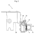
- Fig. 2 is a plan view of the mixing apparatus in Fig. 1.
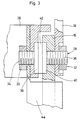
- Fig. 3 is an enlarged side sectional view of a part (around a linking member) of the mixing apparatus in Fig. 1.
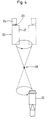
- Fig. 4 is an explanatory view for explaining the mixing operation of the mixing apparatus in Fig. 1.
- vessels for containing a liquid to be mixed suitable ones having various sizes, shapes and materials are selectively used.
- An example thereof is what is known as a cuvette made of plastic or glass which can contain 50 to 300 ⁇ l of a liquid to be measured such as a sample or a reagent.
- the hand member is constructed to be able to hold or release the upper, the middle or the like portion of the vessel located at a prescribed position of a rack, a turntable or the like, depending on the needs.
- the hand member to be used is, for example, one which comprises a pair of right and left board-like members and a coil spring stretched over the end portions of the board-like members in such a manner that the pair of board-like members are pivoted at each of the base end portions to be horizontally rotatable by an urging power of the coil spring.
- the holding portions of these board-like members are adapted to have a suitable shape and structure in accordance with the external shape, the material or the like of the vessel to be held.
- the holding portions of the board-like members have a recessed portion in accordance with the cylindrical shape of the vessel so as to hold the vessel firmly in the recessed portion, or are formed of a resilient material.
- the method for holding a vessel by the hand member employs gripping and holding, in a sandwich-like configuration, of an external upper surface of the vessel in a state in which the liquid may not spill out of the vessel when the mixing apparatus is in operation, for example, in a state in which the vessel is substantially vertical.
- the hand member is constructed to hold one vessel.
- the hand member may be constructed to hold a plurality of vessels in a row in accordance with the needs. By using such a hand member, it is possible to mix liquids in a plurality of vessels simultaneously.
- the holding and releasing of the hand member are actuated by, for example, a forward and backward movement of the hand member based on the horizontal back and forth movement of the mobile member linked to the hand member via the support member and the linking member.
- the support member supports the hand member.
- the hand member comprises the above-mentioned board-like members and the coil spring
- the support member may be, for example, a vertical board-like member supporting the base end portion of each of the board-like members for pivoting movement.
- the mobile member is linked to the support member via the linking member and moves in a predetermined region.
- the predetermined region herein referred to represents a determined region of movement selected from a linear region (one-dimensional region), a planar region (two-dimensional region), a spatial region (three-dimensional region).
- the vibration motor is mounted to the support member and generates an eccentric rotational movement.
- An example of the vibration motor to be used is a small-sized DC coreless motor.
- the rotation speed of the vibration motor is adjusted to be in the range of, for example, 5000 to 10000rpm. More preferably, the rotation speed is in the range of, for example, 7000 to 8000rpm.
- the linking member links the support member and the mobile member into a semi-fixed state.
- the linking connection is adapted in such a manner that the support member is capable of conical revolution movement with respect to the mobile member when the vibration motor is driven.
- the conical revolution movement herein referred to represents a movement wherein, when the support member revolves with respect to a point serving as a fulcrum, the support member describes a trajectory of a conical shape with its apex at the above-mentioned fulcrum and with its base having a circular shape.
- This movement of the support member enables the vessel held by the hand member to eccentrically revolve to rotate and mix the liquid in the vessel.
- the radius and the speed of this revolution movement are determined by the eccentricity and the rotation speed of the vibration motor, the position of the above fulcrum, and others.
- the hand member is mounted on one side of the support member and the vibration motor is mounted on the other side of the support member.
- the support member revolves with a fulcrum at the linking portion linking the support member to the mobile member.
- the linking member comprises a resilient member and that the support member is linked to the mobile member via the resilient member.
- the resilient member transmits and amplifies the eccentric rotational movement of the vibration motor and changes the movement into a conical revolution movement of the support member.
- a urethane rubber, a foamed sponge, or a coil spring may be preferably used as the resilient member.
- the Shore hardness (JIS) of the urethane rubber to be used is preferably in the range of 20 to 50 degrees, more preferably in the range of 30 to 40 degrees when a liquid of about 50 to 300 ⁇ l is to be mixed.
- the vibration motor preferably comprises a motor body and a weight, the weight being eccentrically mounted to the motor shaft of the motor body and having a cross section of a generally semicircular shape.
- Fig. 1 to Fig. 4 are views showing a mixing apparatus D according to an embodiment of the present invention.
- Fig. 1 is a side view of the mixing apparatus D.
- Fig. 2 is a plan view of the mixing apparatus D.
- Fig. 3 is an enlarged side sectional view of a part (around a linking member) of the mixing apparatus D.
- Fig. 4 is an explanatory view for explaining the mixing operation of the mixing apparatus D.
- the reference numeral 10 represents a vessel made of plastic for containing and holding a subject liquid sample and a liquid reagent and for generating a prescribed reaction by mixing of the sample with the reagent.
- the vessel 10 is transparent if the change in optical characteristics (scattered light intensity) of the mixed solution is to be measured.
- the vessel 10 is gripped and held from the right and left sides by a hand member 12.
- the hand member 12 comprises a pair of horizontally disposed right and left board-like members and a coil spring 14 stretched over the base end portions of the board-like members.
- the hand member 12 is constructed in such a manner that the pair of board-like members are pivoted at each of the base end portions to be horizontally revolvable by an urging power of the coil spring 14 at the bottom of a vertically disposed rectangular board-like support member 16.
- the reference numeral 20 represents a vibration motor, which is integrally mounted to the support member 16 by upper and lower board-like mounting members 18 and 22 at the top of the support member 16.
- the vibration motor 20 comprises a DC coreless motor body 21 and an eccentric weight 24, the weight 24 being eccentrically mounted to a motor shaft 23 of the motor body 21.
- the rotation of the weight 24 allows the motor body 21 to conically revolve and vibrate.
- the weight 24 preferably has a large moment with respect to the motor shaft 23.
- the weight 24 is adapted to have a semicircular cross section (the shape of a circular cylinder longitudinally halved along the motor shaft 23).
- the reference numeral 26 represents a mobile member which moves in a prescribed region by a mechanism not shown.
- the mobile member 26 moves in three-dimensional directions (in X, Y, and Z axis directions).
- the mechanism therefor can be provided by a known art.
- the mobile member 26 and the support member 16 are linked by a linking member 28. However, they are not completely fixed but are linked in a semi-fixed state.
- the semi-fixed state herein referred to represents a state in which the support member 16 is linked to the mobile member 26 with some three-dimensional degree of freedom.
- the linking member 28 comprises a resilient member 42, via which the mobile member 26 is linked to the support member 16. More specifically explained, the linking member 28 is constructed by contacting and linking a first member 34 and a second member 36 with each other by using the resilient member 42, the first and second members 34 and 36 being made of metal and having flange portions 38 and 40, respectively.
- the linking is such that the mobile member 26 contacts with the flange portion 38 on one side, the support member 16 contacts with the flange portion 40 on the other side, and there is a gap between the mobile member 26 and the support member 16.
- the resilient member 42 has a disk-like shape with a diameter of 7mm and a thickness of lmm and, specifically, is made of an ether type polyurethane ("Sorbothane” manufactured by Sanshin Enterprises Co., Ltd. in Japan) having a hardness in the range of 30 to 50 when measured by a Shore (OO scale) hardness meter.
- an ether type polyurethane (“Sorbothane” manufactured by Sanshin Enterprises Co., Ltd. in Japan) having a hardness in the range of 30 to 50 when measured by a Shore (OO scale) hardness meter.
- the linking member 28 has only to link the support member 16 to the mobile member 26 so that the support member 16 is conically revolvable with the linking portion serving as a fulcrum.
- the same operational effect can be obtained by providing a male screw member and an O-ring and by linking the members 26 and 16 using a nut member via the O-ring.
- the support member 16 has only to be loosely linked to the mobile member 26.
- the linking between the support member 16 and the mobile member 26 may be constructed as follows in order to generate the conical revolution movement.
- the linking member 28 is formed with a bar-like member having a screw portion and with a resilient member (for example, an O-ring or a coil spring) penetrating through the bar-like member.
- the mobile member 26 and the support member 16 respectively contact with the resilient member, and there is a gap between the mobile member 26 and the support member 16.
- the linking member 28 may be constructed by providing a ball member between the first and second members.
- the support member 16 By thus linking the mobile member 26 to the support member 16, the support member 16 revolves conically with the linking portion serving as a fulcrum 46 by the rotation of the vibration motor 20, as shown in Fig. 4.
- the liquid (sample + reagent) contained in the vessel 10 conically revolves to be suitably mixed.
- Figs. 1 to 4 show a construction in which, in view of facility in construction and others, the vibration motor 20 is disposed on one side of the support member 16, the hand member 12 is disposed on the other side, and the linking member 28 (the fulcrum 46) is disposed therebetween. Alternatively, however, the vibration motor 20 may be provided on the side of the hand member 12.
- the hand member 12 proceeds toward an empty vessel 10 to grip and hold the empty vessel 10 at a predetermined position by pressing.
- the hand member 12 rises and moves to a different position so that a sample of 50 to 100 ⁇ l is dispensed into the vessel 10.
- the hand member 12 further moves to a different position so that a reagent of 50 to 200 ⁇ l is dispensed into the vessel 10.
- the liquid is immediately mixed for a prescribed amount of time (for example, 0.6 seconds) by the driven motion of the vibration motor 20.
- the rotation speed of the vibration motor 20 for mixing may be any amount of time, for example, 7500 ⁇ 500 rpm.
- the hand member 12 moves to a measuring portion to release the vessel 10, whereby the optical characteristics of the mixed liquid in the vessel 10 are measured. After the measurement, the vessel 10 is discarded.
- the mixing apparatus D is constructed in such a manner that the vibration motor 20 is disposed on one side of the support member 16, the hand member 12 is disposed on the other side, and the linking member 28 (the fulcrum 46) is disposed therebetween, whereby the support member 16 conically revolves by the driven motion of the vibration motor 20 with the linking portion serving as the fulcrum 46.
- the vibration motor 20 comprises the eccentric weight 24, and the linking member 28 comprises the resilient member 42. Accordingly, the liquid (sample + reagent) in the vessel 10 conically revolves to be suitably mixed. Further, when the vibration motor 20 stops, the support member 16 halts at its original location, irrespective of the position at which the motor shaft 23 stops.
- the mixing apparatus according to the present invention is constructed in such a manner as in the above, the mixing apparatus produces the following remarkable effects.
- the mixing apparatus comprises a hand member for holding a vessel for containing a liquid to be mixed, a support member for supporting the hand member, a mobile member which moves in a predetermined region, a vibration motor mounted to the support member, and a linking member for linking the support member to the mobile member so that the support member is conically revolvable with respect to the mobile member when the vibration motor is driven.
- the eccentric rotational movement of the vibration motor mounted to the support member is converted to the conical revolving movement by the linking member, thereby allowing the hand member to revolve.
- the liquid in the vessel held by the hand member revolves along the inner surface of the vessel to be suitably mixed. This can prevent the possibility of mixing nonuniformity and contamination.
- the mixing apparatus according to the present invention employs a small and simple mechanism, and is advantageous with respect to costs.
- the mixing apparatus does not particularly need a control mechanism for determining the position of the vessel.
- the hand member is disposed on one side of the support member, and the vibration motor is disposed on the other side of the support member, thereby allowing the support member to revolve with a fulcrum at a linking portion linking the support member to the mobile member. Therefore, the effect produced by the mixing apparatus according to the present invention can be simply and securely achieved by a mixing apparatus which employs a small and simple mechanism and which is advantageous with respect to costs.
- the linking member comprises a resilient member via which the support member is linked to the mobile member, allowing the support member to conically revolve well in such a simple construction. Therefore, the effect produced by the mixing apparatus according to the present invention can be more securely achieved.
- the vibration motor comprises a motor body and a weight, the weight being eccentrically mounted to a motor shaft of the motor body and having a semicircular cross section. Therefore, the effect produced by the mixing apparatus according to the present invention can be more effectively and smoothly obtained.
Landscapes
- Life Sciences & Earth Sciences (AREA)
- Health & Medical Sciences (AREA)
- Chemical Kinetics & Catalysis (AREA)
- Chemical & Material Sciences (AREA)
- Biomedical Technology (AREA)
- Molecular Biology (AREA)
- Pathology (AREA)
- Engineering & Computer Science (AREA)
- Physics & Mathematics (AREA)
- Heart & Thoracic Surgery (AREA)
- Medical Informatics (AREA)
- Biophysics (AREA)
- Surgery (AREA)
- Animal Behavior & Ethology (AREA)
- General Health & Medical Sciences (AREA)
- Public Health (AREA)
- Veterinary Medicine (AREA)
- Mixers With Rotating Receptacles And Mixers With Vibration Mechanisms (AREA)
- Automatic Analysis And Handling Materials Therefor (AREA)
Abstract
Description
- The present invention relates to a mixing apparatus for mixing a liquid in a vessel. More particularly, it relates to a mixing apparatus utilized for well mixing of a liquid sample and a liquid reagent contained in a vessel in an automatic analyzer.
- Conventionally, an automatic analyzer such as a blood coagulation measuring apparatus for measuring the coagulability of blood involves mixing of a subject liquid sample (plasma) and a liquid reagent in a vessel.
- Known apparatus for mixing a liquid in a vessel are, for example, one which allows the liquid to be discharged into the vessel and makes use of the discharging pressure for mixing (Apparatus A), one which allows a bar-like member to be inserted into the vessel containing the liquid and utilizes the bar-like member for mixing (Apparatus B), and one which allows an eccentric rotational movement of the vessel containing the liquid for mixing (Apparatus C) as disclosed in Japanese Examined Utility Model Publication No. Hei. 5(1993)-9069.
- Apparatus A is liable to cause mixing nonuniformity because it utilizes discharging pressure. Apparatus B necessitates washing of the bar-like member every time the mixing is conducted and, moreover, when the washing is insufficient, it may possibly cause mutual contamination of liquids. Apparatus C has a drawback that it tends to be large and mechanically complicated. Moreover, there is a problem of control that the driving source such as the motor must be stopped at a predetermined position to place the vessel at a prescribed location after the mixing.
- The present invention has been made in view of the above circumstances, and the purpose thereof is to provide a mixing apparatus which can prevent the possibility of generating mixing nonuniformity or contamination, employs a small and simple mechanism, and is advantageous with respect to costs.
- Accordingly, the present invention provides a mixing apparatus comprising: a hand member for holding a vessel for containing a liquid to be mixed; a support member for supporting the hand member; a mobile member which moves in a predetermined region; a vibration motor mounted to the support member; and a linking member for linking the support member to the mobile member so that the support member is conically revolvable with respect to the mobile member when the vibration motor is driven, thereby enabling conical revolution movement of the vessel held by the hand member.
- Fig. 1 is a side view of a mixing apparatus according to one embodiment of the present invention.
- Fig. 2 is a plan view of the mixing apparatus in Fig. 1.
- Fig. 3 is an enlarged side sectional view of a part (around a linking member) of the mixing apparatus in Fig. 1.
- Fig. 4 is an explanatory view for explaining the mixing operation of the mixing apparatus in Fig. 1.
- As the vessels for containing a liquid to be mixed, suitable ones having various sizes, shapes and materials are selectively used. An example thereof is what is known as a cuvette made of plastic or glass which can contain 50 to 300 µl of a liquid to be measured such as a sample or a reagent.
- The hand member is constructed to be able to hold or release the upper, the middle or the like portion of the vessel located at a prescribed position of a rack, a turntable or the like, depending on the needs. The hand member to be used is, for example, one which comprises a pair of right and left board-like members and a coil spring stretched over the end portions of the board-like members in such a manner that the pair of board-like members are pivoted at each of the base end portions to be horizontally rotatable by an urging power of the coil spring.
- The holding portions of these board-like members are adapted to have a suitable shape and structure in accordance with the external shape, the material or the like of the vessel to be held. For example, if the vessel has a cylindrical shape, the holding portions of the board-like members have a recessed portion in accordance with the cylindrical shape of the vessel so as to hold the vessel firmly in the recessed portion, or are formed of a resilient material.
- The method for holding a vessel by the hand member employs gripping and holding, in a sandwich-like configuration, of an external upper surface of the vessel in a state in which the liquid may not spill out of the vessel when the mixing apparatus is in operation, for example, in a state in which the vessel is substantially vertical.
- Generally, the hand member is constructed to hold one vessel. Alternatively, however, the hand member may be constructed to hold a plurality of vessels in a row in accordance with the needs. By using such a hand member, it is possible to mix liquids in a plurality of vessels simultaneously.
- The holding and releasing of the hand member are actuated by, for example, a forward and backward movement of the hand member based on the horizontal back and forth movement of the mobile member linked to the hand member via the support member and the linking member.
- The support member supports the hand member. If the hand member comprises the above-mentioned board-like members and the coil spring, the support member may be, for example, a vertical board-like member supporting the base end portion of each of the board-like members for pivoting movement.
- The mobile member is linked to the support member via the linking member and moves in a predetermined region. The predetermined region herein referred to represents a determined region of movement selected from a linear region (one-dimensional region), a planar region (two-dimensional region), a spatial region (three-dimensional region).
- The vibration motor is mounted to the support member and generates an eccentric rotational movement. An example of the vibration motor to be used is a small-sized DC coreless motor. Preferably, the rotation speed of the vibration motor is adjusted to be in the range of, for example, 5000 to 10000rpm. More preferably, the rotation speed is in the range of, for example, 7000 to 8000rpm.
- The linking member links the support member and the mobile member into a semi-fixed state. The linking connection is adapted in such a manner that the support member is capable of conical revolution movement with respect to the mobile member when the vibration motor is driven. The conical revolution movement herein referred to represents a movement wherein, when the support member revolves with respect to a point serving as a fulcrum, the support member describes a trajectory of a conical shape with its apex at the above-mentioned fulcrum and with its base having a circular shape. This movement of the support member enables the vessel held by the hand member to eccentrically revolve to rotate and mix the liquid in the vessel. The radius and the speed of this revolution movement are determined by the eccentricity and the rotation speed of the vibration motor, the position of the above fulcrum, and others.
- If one wishes to attach importance to obtaining a mixing apparatus which employs a small and simple mechanism and is advantageous with respect to costs, it is more preferable that the hand member is mounted on one side of the support member and the vibration motor is mounted on the other side of the support member. In such a case, the support member revolves with a fulcrum at the linking portion linking the support member to the mobile member.
- In order that the above revolution movement is well generated in a simple construction, it is preferable that the linking member comprises a resilient member and that the support member is linked to the mobile member via the resilient member. In other words, the resilient member transmits and amplifies the eccentric rotational movement of the vibration motor and changes the movement into a conical revolution movement of the support member. As the resilient member, a urethane rubber, a foamed sponge, or a coil spring may be preferably used. The Shore hardness (JIS) of the urethane rubber to be used is preferably in the range of 20 to 50 degrees, more preferably in the range of 30 to 40 degrees when a liquid of about 50 to 300 µl is to be mixed.
- In view of generating the above revolution movement more effectively and smoothly, the vibration motor preferably comprises a motor body and a weight, the weight being eccentrically mounted to the motor shaft of the motor body and having a cross section of a generally semicircular shape.
- The present invention will be hereinafter detailed, in conjunction with the attached drawings, by way of an embodiment thereof, which is not to be construed as being intended to limit the scope of the present invention.
- Fig. 1 to Fig. 4 are views showing a mixing apparatus D according to an embodiment of the present invention. Fig. 1 is a side view of the mixing apparatus D. Fig. 2 is a plan view of the mixing apparatus D. Fig. 3 is an enlarged side sectional view of a part (around a linking member) of the mixing apparatus D. Fig. 4 is an explanatory view for explaining the mixing operation of the mixing apparatus D.
- In Figs. 1 and 2, the
reference numeral 10 represents a vessel made of plastic for containing and holding a subject liquid sample and a liquid reagent and for generating a prescribed reaction by mixing of the sample with the reagent. Thevessel 10 is transparent if the change in optical characteristics (scattered light intensity) of the mixed solution is to be measured. - The
vessel 10 is gripped and held from the right and left sides by ahand member 12. Thehand member 12 comprises a pair of horizontally disposed right and left board-like members and acoil spring 14 stretched over the base end portions of the board-like members. Thehand member 12 is constructed in such a manner that the pair of board-like members are pivoted at each of the base end portions to be horizontally revolvable by an urging power of thecoil spring 14 at the bottom of a vertically disposed rectangular board-like support member 16. - The
reference numeral 20 represents a vibration motor, which is integrally mounted to thesupport member 16 by upper and lower board-like mounting members support member 16. Thevibration motor 20 comprises a DCcoreless motor body 21 and aneccentric weight 24, theweight 24 being eccentrically mounted to amotor shaft 23 of themotor body 21. The rotation of theweight 24 allows themotor body 21 to conically revolve and vibrate. In order to increase the amplitude of the conical revolution vibration, theweight 24 preferably has a large moment with respect to themotor shaft 23. In view of this, theweight 24 is adapted to have a semicircular cross section (the shape of a circular cylinder longitudinally halved along the motor shaft 23). - The
reference numeral 26 represents a mobile member which moves in a prescribed region by a mechanism not shown. Themobile member 26 moves in three-dimensional directions (in X, Y, and Z axis directions). The mechanism therefor can be provided by a known art. - The
mobile member 26 and thesupport member 16 are linked by a linkingmember 28. However, they are not completely fixed but are linked in a semi-fixed state. The semi-fixed state herein referred to represents a state in which thesupport member 16 is linked to themobile member 26 with some three-dimensional degree of freedom. - Referring to Fig. 3, the periphery (the linking portion) of the linking
member 28 will be hereinafter explained. Themobile member 26 and thesupport member 16 are linked by screwing the linkingmember 28 withnut members reference numeral 44 represents a protection cover. The linkingmember 28 comprises aresilient member 42, via which themobile member 26 is linked to thesupport member 16. More specifically explained, the linkingmember 28 is constructed by contacting and linking afirst member 34 and asecond member 36 with each other by using theresilient member 42, the first andsecond members flange portions - In other words, the linking is such that the
mobile member 26 contacts with theflange portion 38 on one side, thesupport member 16 contacts with theflange portion 40 on the other side, and there is a gap between themobile member 26 and thesupport member 16. - Here, the
resilient member 42 has a disk-like shape with a diameter of 7mm and a thickness of lmm and, specifically, is made of an ether type polyurethane ("Sorbothane" manufactured by Sanshin Enterprises Co., Ltd. in Japan) having a hardness in the range of 30 to 50 when measured by a Shore (OO scale) hardness meter. - The linking
member 28 has only to link thesupport member 16 to themobile member 26 so that thesupport member 16 is conically revolvable with the linking portion serving as a fulcrum. The same operational effect can be obtained by providing a male screw member and an O-ring and by linking themembers - The
support member 16 has only to be loosely linked to themobile member 26. The linking between thesupport member 16 and themobile member 26 may be constructed as follows in order to generate the conical revolution movement. The linkingmember 28 is formed with a bar-like member having a screw portion and with a resilient member (for example, an O-ring or a coil spring) penetrating through the bar-like member. Themobile member 26 and thesupport member 16 respectively contact with the resilient member, and there is a gap between themobile member 26 and thesupport member 16. Alternatively, the linkingmember 28 may be constructed by providing a ball member between the first and second members. - By thus linking the
mobile member 26 to thesupport member 16, thesupport member 16 revolves conically with the linking portion serving as afulcrum 46 by the rotation of thevibration motor 20, as shown in Fig. 4. In accordance with this movement, the liquid (sample + reagent) contained in thevessel 10 conically revolves to be suitably mixed. - Figs. 1 to 4 show a construction in which, in view of facility in construction and others, the
vibration motor 20 is disposed on one side of thesupport member 16, thehand member 12 is disposed on the other side, and the linking member 28 (the fulcrum 46) is disposed therebetween. Alternatively, however, thevibration motor 20 may be provided on the side of thehand member 12. - Next, an overall operation of the mixing apparatus D will be briefly explained. First, by the forward movement of the
mobile member 26, thehand member 12 proceeds toward anempty vessel 10 to grip and hold theempty vessel 10 at a predetermined position by pressing. - Then, the
hand member 12 rises and moves to a different position so that a sample of 50 to 100 µl is dispensed into thevessel 10. Thehand member 12 further moves to a different position so that a reagent of 50 to 200 µl is dispensed into thevessel 10. - After the reagent is dispensed, the liquid is immediately mixed for a prescribed amount of time (for example, 0.6 seconds) by the driven motion of the
vibration motor 20. The rotation speed of thevibration motor 20 for mixing may be any amount of time, for example, 7500 ± 500 rpm. After mixing, thehand member 12 moves to a measuring portion to release thevessel 10, whereby the optical characteristics of the mixed liquid in thevessel 10 are measured. After the measurement, thevessel 10 is discarded. - The mixing apparatus D is constructed in such a manner that the
vibration motor 20 is disposed on one side of thesupport member 16, thehand member 12 is disposed on the other side, and the linking member 28 (the fulcrum 46) is disposed therebetween, whereby thesupport member 16 conically revolves by the driven motion of thevibration motor 20 with the linking portion serving as thefulcrum 46. Also, thevibration motor 20 comprises theeccentric weight 24, and the linkingmember 28 comprises theresilient member 42. Accordingly, the liquid (sample + reagent) in thevessel 10 conically revolves to be suitably mixed. Further, when thevibration motor 20 stops, thesupport member 16 halts at its original location, irrespective of the position at which themotor shaft 23 stops. - Since the mixing apparatus according to the present invention is constructed in such a manner as in the above, the mixing apparatus produces the following remarkable effects.
- In other words, the mixing apparatus according to the present invention comprises a hand member for holding a vessel for containing a liquid to be mixed, a support member for supporting the hand member, a mobile member which moves in a predetermined region, a vibration motor mounted to the support member, and a linking member for linking the support member to the mobile member so that the support member is conically revolvable with respect to the mobile member when the vibration motor is driven. Accordingly, the eccentric rotational movement of the vibration motor mounted to the support member is converted to the conical revolving movement by the linking member, thereby allowing the hand member to revolve. By this movement, the liquid in the vessel held by the hand member revolves along the inner surface of the vessel to be suitably mixed. This can prevent the possibility of mixing nonuniformity and contamination. Also, the mixing apparatus according to the present invention employs a small and simple mechanism, and is advantageous with respect to costs. Moreover, the mixing apparatus does not particularly need a control mechanism for determining the position of the vessel.
- In the mixing apparatus according to the invention, the hand member is disposed on one side of the support member, and the vibration motor is disposed on the other side of the support member, thereby allowing the support member to revolve with a fulcrum at a linking portion linking the support member to the mobile member. Therefore, the effect produced by the mixing apparatus according to the present invention can be simply and securely achieved by a mixing apparatus which employs a small and simple mechanism and which is advantageous with respect to costs.
- In the mixing apparatus according to the invention, the linking member comprises a resilient member via which the support member is linked to the mobile member, allowing the support member to conically revolve well in such a simple construction. Therefore, the effect produced by the mixing apparatus according to the present invention can be more securely achieved.
- In the mixing apparatus according to the invention, the vibration motor comprises a motor body and a weight, the weight being eccentrically mounted to a motor shaft of the motor body and having a semicircular cross section. Therefore, the effect produced by the mixing apparatus according to the present invention can be more effectively and smoothly obtained.
Claims (8)
- A mixing apparatus comprising :a hand member (12) for holding a vessel (10) for containing a liquide to be mixed ;a support member (16) for supporting the hand member (12) ;a mobile member (26) which moves in a predetermined region ;a vibration motor (20) mounted to the support member (16) ; anda linking member (28) for linking the support member (16) to the mobile member (26) so that the support member (16) is capable of conical revolution movement with respect to the mobile member (26) when the vibration motor (20) is driven, thereby enabling conical revolution movement of the vessel (10) held by the hand member (12).
- A mixing apparatus according to claim 1, in which the hand member (12) is disposed on one side of the support member (16), and the vibration motor (20) is disposed on the other side of the support member (16), thereby allowing the support member (16) to perform the conical revolution movement with a fulcrum (46) at a linking portion linking the support member (16) to the mobile member (26).
- A mixing apparatus according to claim 1, in which the linking member (28) comprises a resilient member (42) via which the support member (16) is linked to the mobile member (26).
- A mixing apparatus according to claim 1, in which the hand member (12) comprises a pair of horizontally disposed board-like members and a coil spring (14) stretched over the end portions of the board-like members so that the pair of the board-like members are pivoted at each of the base end portions to be horizontally rotatable by an urging power of the coil spring (14).
- A mixing apparatus according to claim 1, in which the support member (16) has a vertically disposed rectangular board-like shape.
- A mixing apparatus according to claim 1, in which the mobile member (26) is capable of moving in three-dimensional directions.
- A mixing apparatus according to claim 1, in which the vibration motor (20) comprises a motor body (21) and a weight (24), the weight (24) being eccentrically mounted to a motor shaft (23) of the motor body and having a semicircular cross section.
- A mixing apparatus according to claim 1, in which the linking member (28) is constructed by contacting and linking a first member and a second member with each other by intermediation of a resilient member (42) made of polyurethane, the first member (34) being made of a metal and having a flange portion with which the mobile member contacts, and the second member (36) being made of a metal and having a flange portion (38, 40) with which the support member contacts.
Applications Claiming Priority (3)
| Application Number | Priority Date | Filing Date | Title |
|---|---|---|---|
| JP11096595 | 1995-05-09 | ||
| JP110965/95 | 1995-05-09 | ||
| JP11096595A JP3230561B2 (en) | 1995-05-09 | 1995-05-09 | Stirrer |
Publications (2)
| Publication Number | Publication Date |
|---|---|
| EP0742435A1 true EP0742435A1 (en) | 1996-11-13 |
| EP0742435B1 EP0742435B1 (en) | 2002-01-23 |
Family
ID=14549005
Family Applications (1)
| Application Number | Title | Priority Date | Filing Date |
|---|---|---|---|
| EP96400962A Expired - Lifetime EP0742435B1 (en) | 1995-05-09 | 1996-05-06 | Mixing apparatus |
Country Status (7)
| Country | Link |
|---|---|
| US (1) | US5642938A (en) |
| EP (1) | EP0742435B1 (en) |
| JP (1) | JP3230561B2 (en) |
| KR (1) | KR100402650B1 (en) |
| CN (1) | CN1048189C (en) |
| DE (1) | DE69618708T2 (en) |
| TW (1) | TW311102B (en) |
Cited By (2)
| Publication number | Priority date | Publication date | Assignee | Title |
|---|---|---|---|---|
| EP2308588A2 (en) | 2009-10-10 | 2011-04-13 | Siemens Healthcare Diagnostics Products GmbH | Device and method for mixing a liquid sample |
| EP3173794A1 (en) | 2015-11-25 | 2017-05-31 | Siemens Healthcare Diagnostics Products GmbH | Method for transferring a fluid volume in an analyzer |
Families Citing this family (15)
| Publication number | Priority date | Publication date | Assignee | Title |
|---|---|---|---|---|
| US6979307B2 (en) * | 1997-06-24 | 2005-12-27 | Cascade Medical Enterprises Llc | Systems and methods for preparing autologous fibrin glue |
| US5947594A (en) * | 1998-03-19 | 1999-09-07 | Dolatli; George | Agitator device with vibrating clamping member |
| KR100340950B1 (en) * | 1999-08-06 | 2002-06-20 | 신성균 | Sample Mixer |
| US20080190857A1 (en) * | 2005-03-22 | 2008-08-14 | Cascade Medical Entrprises, Llc | System and Methods of Producing Membranes |
| JP4018131B2 (en) | 2005-07-27 | 2007-12-05 | シスメックス株式会社 | Cuvette |
| CN100560194C (en) * | 2005-10-28 | 2009-11-18 | 鸿富锦精密工业(深圳)有限公司 | Mixing device for heat radiation paste |
| JP4768410B2 (en) * | 2005-11-15 | 2011-09-07 | シスメックス株式会社 | Stirring device and sample analyzer |
| US20070172390A1 (en) | 2006-01-23 | 2007-07-26 | Sysmex Corporation | Analyzing apparatus, solid-liquid separation device and solid-liquid separation method |
| JP6014424B2 (en) * | 2012-08-30 | 2016-10-25 | シスメックス株式会社 | Stirring device and sample analyzer |
| JP6324865B2 (en) | 2014-09-30 | 2018-05-16 | シスメックス株式会社 | Analytical apparatus and stirring unit |
| CN104474951B (en) * | 2014-12-17 | 2023-07-14 | 重庆康乐制药有限公司 | Clamping type vibration emulsifying device |
| ES2701914T3 (en) * | 2016-03-10 | 2019-02-26 | Siemens Healthcare Diagnostics Products Gmbh | Procedure for mixing a liquid in an automatic analysis device |
| CN109021274B (en) * | 2018-06-26 | 2021-06-25 | 泗县微腾知识产权运营有限公司 | Preparation method of straw fireproof insulation board |
| AU2023266199A1 (en) * | 2022-05-03 | 2024-12-12 | Thomas Edwards | Enhanced mixing device, system and method of mixing |
| GB2610674A (en) * | 2022-05-03 | 2023-03-15 | Joseph Edwards Thomas | Mixing device, system and method for mixing |
Citations (1)
| Publication number | Priority date | Publication date | Assignee | Title |
|---|---|---|---|---|
| US4943164A (en) * | 1988-08-26 | 1990-07-24 | Hitachi, Ltd. | Mixing apparatus for mixing reagent for use in automatic chemistry analyzer |
Family Cites Families (7)
| Publication number | Priority date | Publication date | Assignee | Title |
|---|---|---|---|---|
| US3061280A (en) * | 1959-04-06 | 1962-10-30 | Kraft Scient Corp | Apparatus for mixing fluent material |
| US3159384A (en) * | 1962-07-02 | 1964-12-01 | Bio Science Labor | Agitator for laboratory tubes and flasks |
| US4555183A (en) * | 1984-02-06 | 1985-11-26 | Reese Scientific Corporation | High speed test tube agitator apparatus |
| SE449964B (en) * | 1985-02-12 | 1987-06-01 | Skandex Ab | APPLIANCE FOR MIXING THE CONTENT IN A CLOSED PACKAGING LIKE A PREPARATION |
| CA1313616C (en) * | 1987-06-01 | 1993-02-16 | Robert B. Sargeant | Lateral flow, non-bibulous membrane protocols |
| US5431201A (en) * | 1993-12-03 | 1995-07-11 | Technology 2000 Incororated | Robotic admixture system |
| US5466065A (en) * | 1994-04-13 | 1995-11-14 | Catrombon; George T. | Conical motion mixing machine |
-
1995
- 1995-05-09 JP JP11096595A patent/JP3230561B2/en not_active Expired - Fee Related
-
1996
- 1996-04-11 TW TW085104295A patent/TW311102B/zh not_active IP Right Cessation
- 1996-05-02 KR KR1019960014212A patent/KR100402650B1/en not_active IP Right Cessation
- 1996-05-06 DE DE69618708T patent/DE69618708T2/en not_active Expired - Lifetime
- 1996-05-06 EP EP96400962A patent/EP0742435B1/en not_active Expired - Lifetime
- 1996-05-07 US US08/646,034 patent/US5642938A/en not_active Expired - Lifetime
- 1996-05-09 CN CN96110025A patent/CN1048189C/en not_active Expired - Lifetime
Patent Citations (1)
| Publication number | Priority date | Publication date | Assignee | Title |
|---|---|---|---|---|
| US4943164A (en) * | 1988-08-26 | 1990-07-24 | Hitachi, Ltd. | Mixing apparatus for mixing reagent for use in automatic chemistry analyzer |
Cited By (6)
| Publication number | Priority date | Publication date | Assignee | Title |
|---|---|---|---|---|
| EP2308588A2 (en) | 2009-10-10 | 2011-04-13 | Siemens Healthcare Diagnostics Products GmbH | Device and method for mixing a liquid sample |
| DE102009048918A1 (en) | 2009-10-10 | 2011-04-14 | Siemens Healthcare Diagnostics Products Gmbh | Device for mixing a liquid sample |
| EP2308588A3 (en) * | 2009-10-10 | 2012-10-03 | Siemens Healthcare Diagnostics Products GmbH | Device and method for mixing a liquid sample |
| US8899821B2 (en) | 2009-10-10 | 2014-12-02 | Siemens Healthcare Diagnostics Products Gmbh | Device having a detachable connection between a sample holder and a shaking apparatus for mixing a liquid sample |
| EP3173794A1 (en) | 2015-11-25 | 2017-05-31 | Siemens Healthcare Diagnostics Products GmbH | Method for transferring a fluid volume in an analyzer |
| US10365291B2 (en) | 2015-11-25 | 2019-07-30 | Siemens Healthcare Diagnostics Products Gmbh | Method for transferring a liquid volume in an analyzer |
Also Published As
| Publication number | Publication date |
|---|---|
| DE69618708T2 (en) | 2002-08-14 |
| JP3230561B2 (en) | 2001-11-19 |
| DE69618708D1 (en) | 2002-03-14 |
| CN1048189C (en) | 2000-01-12 |
| TW311102B (en) | 1997-07-21 |
| CN1154266A (en) | 1997-07-16 |
| JPH08299775A (en) | 1996-11-19 |
| EP0742435B1 (en) | 2002-01-23 |
| KR960040312A (en) | 1996-12-17 |
| KR100402650B1 (en) | 2004-02-11 |
| US5642938A (en) | 1997-07-01 |
Similar Documents
| Publication | Publication Date | Title |
|---|---|---|
| EP0742435B1 (en) | Mixing apparatus | |
| AU618956B2 (en) | Device for mixing at least one aqueous fluid substance | |
| US4702610A (en) | Undulating mixing device | |
| CA1167437A (en) | Apparatus and method for the controlled, non-invasive mixing of substances | |
| US4259289A (en) | Apparatus for retrieving liquid samples from test tubes | |
| SE432890B (en) | APPARATUS FOR ROTATING REACTION BATTERIES IN SLANING | |
| JPH02502126A (en) | Biological sample mixing device and method | |
| EP0525577B1 (en) | Carrier device | |
| JP3580864B2 (en) | Stirrer | |
| JPH0621853B2 (en) | Device for preparing and carrying out sedimentation velocity test | |
| JPH06509277A (en) | vortex mixer drive | |
| US6781689B2 (en) | Continuous inspection apparatus | |
| EP2023148A1 (en) | Analytical instrument | |
| EP1434027A3 (en) | Apparatus for measuring angular position and displacement of a rotary table and accuracy analyzing apparatus therefor | |
| JPWO2020166127A1 (en) | Specimen rack, sample rack adapter and automatic analyzer | |
| JPH0583298B2 (en) | ||
| JPH08294478A (en) | Blood drawing apparatus | |
| JP3481732B2 (en) | Automatic analyzer | |
| JP4201271B2 (en) | Sample holding device and X-ray diffractometer using the same | |
| US3876380A (en) | Mixing device | |
| JP2000275251A (en) | Automatic analysing device and reagent vessel | |
| JP3179581B2 (en) | Stirring device and device provided with the same | |
| JPH0843407A (en) | Automatic instrument for chemical analysis | |
| JPH03296429A (en) | Mixing apparatus | |
| JPH04296654A (en) | Automatic analyzing device |
Legal Events
| Date | Code | Title | Description |
|---|---|---|---|
| PUAI | Public reference made under article 153(3) epc to a published international application that has entered the european phase |
Free format text: ORIGINAL CODE: 0009012 |
|
| AK | Designated contracting states |
Kind code of ref document: A1 Designated state(s): DE FR GB IT |
|
| 17P | Request for examination filed |
Effective date: 19970505 |
|
| RAP1 | Party data changed (applicant data changed or rights of an application transferred) |
Owner name: SYSMEX CORPORATION |
|
| GRAG | Despatch of communication of intention to grant |
Free format text: ORIGINAL CODE: EPIDOS AGRA |
|
| 17Q | First examination report despatched |
Effective date: 20010510 |
|
| GRAG | Despatch of communication of intention to grant |
Free format text: ORIGINAL CODE: EPIDOS AGRA |
|
| GRAH | Despatch of communication of intention to grant a patent |
Free format text: ORIGINAL CODE: EPIDOS IGRA |
|
| GRAH | Despatch of communication of intention to grant a patent |
Free format text: ORIGINAL CODE: EPIDOS IGRA |
|
| GRAA | (expected) grant |
Free format text: ORIGINAL CODE: 0009210 |
|
| REG | Reference to a national code |
Ref country code: GB Ref legal event code: IF02 |
|
| AK | Designated contracting states |
Kind code of ref document: B1 Designated state(s): DE FR GB IT |
|
| REF | Corresponds to: |
Ref document number: 69618708 Country of ref document: DE Date of ref document: 20020314 |
|
| ET | Fr: translation filed | ||
| PLBE | No opposition filed within time limit |
Free format text: ORIGINAL CODE: 0009261 |
|
| STAA | Information on the status of an ep patent application or granted ep patent |
Free format text: STATUS: NO OPPOSITION FILED WITHIN TIME LIMIT |
|
| 26N | No opposition filed | ||
| PGFP | Annual fee paid to national office [announced via postgrant information from national office to epo] |
Ref country code: IT Payment date: 20100514 Year of fee payment: 15 |
|
| PGFP | Annual fee paid to national office [announced via postgrant information from national office to epo] |
Ref country code: FR Payment date: 20110523 Year of fee payment: 16 |
|
| PGFP | Annual fee paid to national office [announced via postgrant information from national office to epo] |
Ref country code: GB Payment date: 20110504 Year of fee payment: 16 |
|
| PG25 | Lapsed in a contracting state [announced via postgrant information from national office to epo] |
Ref country code: IT Free format text: LAPSE BECAUSE OF NON-PAYMENT OF DUE FEES Effective date: 20110506 |
|
| GBPC | Gb: european patent ceased through non-payment of renewal fee |
Effective date: 20120506 |
|
| REG | Reference to a national code |
Ref country code: FR Ref legal event code: ST Effective date: 20130131 |
|
| PG25 | Lapsed in a contracting state [announced via postgrant information from national office to epo] |
Ref country code: FR Free format text: LAPSE BECAUSE OF NON-PAYMENT OF DUE FEES Effective date: 20120531 Ref country code: GB Free format text: LAPSE BECAUSE OF NON-PAYMENT OF DUE FEES Effective date: 20120506 |
|
| PGFP | Annual fee paid to national office [announced via postgrant information from national office to epo] |
Ref country code: DE Payment date: 20140430 Year of fee payment: 19 |
|
| REG | Reference to a national code |
Ref country code: DE Ref legal event code: R119 Ref document number: 69618708 Country of ref document: DE |
|
| PG25 | Lapsed in a contracting state [announced via postgrant information from national office to epo] |
Ref country code: DE Free format text: LAPSE BECAUSE OF NON-PAYMENT OF DUE FEES Effective date: 20151201 |