EP0742319A2 - Sound absorbing construction for railway track without ballast and slip form paver - Google Patents
Sound absorbing construction for railway track without ballast and slip form paver Download PDFInfo
- Publication number
- EP0742319A2 EP0742319A2 EP96107492A EP96107492A EP0742319A2 EP 0742319 A2 EP0742319 A2 EP 0742319A2 EP 96107492 A EP96107492 A EP 96107492A EP 96107492 A EP96107492 A EP 96107492A EP 0742319 A2 EP0742319 A2 EP 0742319A2
- Authority
- EP
- European Patent Office
- Prior art keywords
- cheek
- soundproofing
- formwork
- building material
- sound
- Prior art date
- Legal status (The legal status is an assumption and is not a legal conclusion. Google has not performed a legal analysis and makes no representation as to the accuracy of the status listed.)
- Withdrawn
Links
- 238000010276 construction Methods 0.000 title claims description 21
- 239000004567 concrete Substances 0.000 claims abstract description 20
- 239000011148 porous material Substances 0.000 claims abstract description 13
- 239000010426 asphalt Substances 0.000 claims abstract description 5
- 238000000034 method Methods 0.000 claims abstract 6
- 238000009415 formwork Methods 0.000 claims description 75
- 239000004566 building material Substances 0.000 claims description 57
- 238000004519 manufacturing process Methods 0.000 claims description 37
- 239000000463 material Substances 0.000 claims description 31
- 239000006096 absorbing agent Substances 0.000 claims description 21
- 239000004568 cement Substances 0.000 claims description 16
- 229920001971 elastomer Polymers 0.000 claims description 15
- 230000008878 coupling Effects 0.000 claims description 8
- 238000010168 coupling process Methods 0.000 claims description 8
- 238000005859 coupling reaction Methods 0.000 claims description 8
- 238000009826 distribution Methods 0.000 claims description 7
- 239000004020 conductor Substances 0.000 claims description 5
- XLYOFNOQVPJJNP-UHFFFAOYSA-N water Substances O XLYOFNOQVPJJNP-UHFFFAOYSA-N 0.000 claims description 4
- 229920003171 Poly (ethylene oxide) Polymers 0.000 claims description 3
- 239000000440 bentonite Substances 0.000 claims description 3
- 229910000278 bentonite Inorganic materials 0.000 claims description 3
- SVPXDRXYRYOSEX-UHFFFAOYSA-N bentoquatam Chemical compound O.O=[Si]=O.O=[Al]O[Al]=O SVPXDRXYRYOSEX-UHFFFAOYSA-N 0.000 claims description 3
- 230000006835 compression Effects 0.000 claims description 3
- 238000007906 compression Methods 0.000 claims description 3
- 229910021487 silica fume Inorganic materials 0.000 claims description 3
- 239000007787 solid Substances 0.000 claims description 3
- 229920003169 water-soluble polymer Polymers 0.000 claims description 3
- 238000009416 shuttering Methods 0.000 abstract 3
- 239000002250 absorbent Substances 0.000 abstract 2
- 239000011248 coating agent Substances 0.000 abstract 1
- 238000000576 coating method Methods 0.000 abstract 1
- 238000005056 compaction Methods 0.000 description 8
- 238000010521 absorption reaction Methods 0.000 description 5
- 238000009413 insulation Methods 0.000 description 5
- 230000006978 adaptation Effects 0.000 description 4
- 230000033001 locomotion Effects 0.000 description 4
- 230000004888 barrier function Effects 0.000 description 3
- 230000005540 biological transmission Effects 0.000 description 3
- 238000005516 engineering process Methods 0.000 description 3
- 239000008187 granular material Substances 0.000 description 3
- 238000009434 installation Methods 0.000 description 3
- 230000009467 reduction Effects 0.000 description 3
- 239000004927 clay Substances 0.000 description 2
- 238000013016 damping Methods 0.000 description 2
- 230000000694 effects Effects 0.000 description 2
- 238000005538 encapsulation Methods 0.000 description 2
- 230000005855 radiation Effects 0.000 description 2
- 230000002787 reinforcement Effects 0.000 description 2
- 230000000284 resting effect Effects 0.000 description 2
- 238000007493 shaping process Methods 0.000 description 2
- 238000009751 slip forming Methods 0.000 description 2
- 239000000758 substrate Substances 0.000 description 2
- 108010053481 Antifreeze Proteins Proteins 0.000 description 1
- 239000000654 additive Substances 0.000 description 1
- 230000002528 anti-freeze Effects 0.000 description 1
- 230000008901 benefit Effects 0.000 description 1
- 239000011230 binding agent Substances 0.000 description 1
- QXJJQWWVWRCVQT-UHFFFAOYSA-K calcium;sodium;phosphate Chemical compound [Na+].[Ca+2].[O-]P([O-])([O-])=O QXJJQWWVWRCVQT-UHFFFAOYSA-K 0.000 description 1
- 239000007795 chemical reaction product Substances 0.000 description 1
- 239000004035 construction material Substances 0.000 description 1
- 230000007613 environmental effect Effects 0.000 description 1
- 230000002349 favourable effect Effects 0.000 description 1
- 238000005243 fluidization Methods 0.000 description 1
- 239000011494 foam glass Substances 0.000 description 1
- 239000006261 foam material Substances 0.000 description 1
- 239000011521 glass Substances 0.000 description 1
- 239000004816 latex Substances 0.000 description 1
- 229920000126 latex Polymers 0.000 description 1
- 238000003908 quality control method Methods 0.000 description 1
- OPKPRGDJBUTJEZ-AGILITTLSA-N ram-336 Chemical class C1([C@]23CCN(C)[C@@H]([C@@]2(CCC(=O)C3)O)CC1=CC=C1OC)=C1OC1=CC=CC=C1 OPKPRGDJBUTJEZ-AGILITTLSA-N 0.000 description 1
- 239000011150 reinforced concrete Substances 0.000 description 1
- 238000005096 rolling process Methods 0.000 description 1
- 238000007789 sealing Methods 0.000 description 1
- 238000000926 separation method Methods 0.000 description 1
- 230000000087 stabilizing effect Effects 0.000 description 1
- 239000004753 textile Substances 0.000 description 1
Images


Classifications
-
- E—FIXED CONSTRUCTIONS
- E01—CONSTRUCTION OF ROADS, RAILWAYS, OR BRIDGES
- E01C—CONSTRUCTION OF, OR SURFACES FOR, ROADS, SPORTS GROUNDS, OR THE LIKE; MACHINES OR AUXILIARY TOOLS FOR CONSTRUCTION OR REPAIR
- E01C19/00—Machines, tools or auxiliary devices for preparing or distributing paving materials, for working the placed materials, or for forming, consolidating, or finishing the paving
- E01C19/48—Machines, tools or auxiliary devices for preparing or distributing paving materials, for working the placed materials, or for forming, consolidating, or finishing the paving for laying-down the materials and consolidating them, or finishing the surface, e.g. slip forms therefor, forming kerbs or gutters in a continuous operation in situ
- E01C19/4886—Machines, tools or auxiliary devices for preparing or distributing paving materials, for working the placed materials, or for forming, consolidating, or finishing the paving for laying-down the materials and consolidating them, or finishing the surface, e.g. slip forms therefor, forming kerbs or gutters in a continuous operation in situ for forming in a continuous operation kerbs, gutters, berms, safety kerbs, median barriers or like structures in situ, e.g. by slip-forming, by extrusion
-
- E—FIXED CONSTRUCTIONS
- E01—CONSTRUCTION OF ROADS, RAILWAYS, OR BRIDGES
- E01B—PERMANENT WAY; PERMANENT-WAY TOOLS; MACHINES FOR MAKING RAILWAYS OF ALL KINDS
- E01B19/00—Protection of permanent way against development of dust or against the effect of wind, sun, frost, or corrosion; Means to reduce development of noise
- E01B19/003—Means for reducing the development or propagation of noise
-
- E—FIXED CONSTRUCTIONS
- E01—CONSTRUCTION OF ROADS, RAILWAYS, OR BRIDGES
- E01F—ADDITIONAL WORK, SUCH AS EQUIPPING ROADS OR THE CONSTRUCTION OF PLATFORMS, HELICOPTER LANDING STAGES, SIGNS, SNOW FENCES, OR THE LIKE
- E01F8/00—Arrangements for absorbing or reflecting air-transmitted noise from road or railway traffic
- E01F8/0005—Arrangements for absorbing or reflecting air-transmitted noise from road or railway traffic used in a wall type arrangement
- E01F8/0023—Details, e.g. foundations
-
- E—FIXED CONSTRUCTIONS
- E01—CONSTRUCTION OF ROADS, RAILWAYS, OR BRIDGES
- E01F—ADDITIONAL WORK, SUCH AS EQUIPPING ROADS OR THE CONSTRUCTION OF PLATFORMS, HELICOPTER LANDING STAGES, SIGNS, SNOW FENCES, OR THE LIKE
- E01F8/00—Arrangements for absorbing or reflecting air-transmitted noise from road or railway traffic
- E01F8/02—Arrangements for absorbing or reflecting air-transmitted noise from road or railway traffic specially adapted for sustaining vegetation or for accommodating plants ; Embankment-type or crib-type noise barriers; Retaining walls specially adapted to absorb or reflect noise
- E01F8/027—Arrangements for absorbing or reflecting air-transmitted noise from road or railway traffic specially adapted for sustaining vegetation or for accommodating plants ; Embankment-type or crib-type noise barriers; Retaining walls specially adapted to absorb or reflect noise with external support, e.g. wall facing
- E01F8/028—Through-type, e.g. between adjacent kerbs
Definitions
- the invention relates to a sound absorber construction for a solid carriageway for track-bound vehicles.
- a sound absorber construction for a solid carriageway for track-bound vehicles comprising a continuous concrete cheek arranged on the side of the pair of rails, which extends beyond the rail level into an area to the side and above the underside of the vehicle.
- the concrete cheeks are each trough-like prefabricated elements into which the sleepers of the track grate are inserted. Manufacture and assembly of these voluminous and accordingly weighty finished parts is complex.
- the invention has for its object to provide a sound absorber construction that is easy to manufacture with good sound insulation.
- the soundproofing cheek is made of concrete or asphalt by means of slipform pavers.
- the soundproofing beam can thus be manufactured quickly and inexpensively and, if necessary, continuously according to the construction progress. Large cross-sectional dimensions with a correspondingly high sound absorption capacity can also be selected.
- the sound absorber construction according to the invention thus leads to an effective reduction in driving noise level.
- the concrete cheek covers the area of the rail and wheel from the side, so that the direct sound path is interrupted. This dampens the transmission of the sound to the outside.
- the underbody of the vehicle is shifted downward over the wheel axles in order to obtain an extensive encapsulation of the wheels. Accordingly, it is sufficient if the soundproofing cheek protrudes 25 to 40 cm, preferably 30 to 35 cm, above the top of the rail in order thereby to encompass the vehicle partially and with a sufficient safety distance.
- the soundproofing cheek is particularly preferably designed with a side surface that is concavely curved toward the rail and the impeller. This has the advantage that sound vibrations emitted by the rail and wheel are reflected back to a greater extent than are deflected laterally outwards, which in turn reduces the lateral sound radiation.
- the cheek can also be brought closer to the vehicle with a correspondingly curved vehicle, with a correspondingly reduced sound outlet gap between the cheek and the vehicle.
- An essentially cylindrically curved side surface with a radius of curvature has proven advantageous here preferably between 35 and 150 cm, more preferably 40 to 80 cm, preferably about 60 cm.
- the soundproofing cheek is provided with a sound-absorbing covering at least on its side surface facing the rail and the impeller.
- the sound-absorbing covering reduces the sound level between the sound absorber and the vehicle. The sound intensity emitted from the side is reduced accordingly, as is the sound level perceptible in the vehicle itself.
- Many materials are suitable for the sound-absorbing covering, such as rigid foam materials or textile materials or rubber materials.
- the use of open-pore foam glass spheres, which are held together by open-pore binders, has proven to be particularly favorable. (Also porous building material, such as bulk concrete, comes into question, in which case the entire soundproofing cheek is particularly preferably produced from this building material, so that the production is accordingly simplified).
- the covering ceiling is preferably 8 to 10 cm, more preferably 6 to 8 cm.
- a cheek head that protrudes from the upper longitudinal edge of the curved side surface in accordance with the thickness of the covering.
- the sound absorbing covering extend into the fastening area of the rail and preferably also in the area between the rails.
- a continuous concrete cheek is preferably provided on both sides of a pair of rails. If two or more pairs of rails lying side by side, the two concrete cheeks between two successive pairs of rails can be designed as separate concrete cheeks, depending on the distance between the two pairs of rails, or can be integrated into a single concrete cheek, which is then formed on both sides with concave curved side surfaces. In the case of separate soundproof walls, the space between the two is preferably filled, preferably with floor material.
- At least one of the sound-absorbing cheeks be formed integrally with a cable receiving channel. This results in significantly reduced manufacturer and installation costs.
- the sound insulation cheek can connect to a continuous support plate on the side.
- the soundproofing beam can also rest on the continuous support plate.
- the soundproofing beam is connected to the support plate via anchors.
- Preferred drainage passages in the soundproofing cheek and / or on the continuous support plate ensure adequate drainage.
- an earthed conductor be arranged on the soundproofing cheek, preferably on the cheek head.
- the conductor is preferably a lightning rod.
- the sound-absorbing covering can also be applied to the previously made soundproofing beam using slipform pavers.
- a bonded expanded glass granulate is preferred for the sound absorber.
- bound expanded clay granulate can also be used, as can bulk concrete.
- the invention also relates to a method for producing a continuous soundproofing cheek of a fixed carriageway for track-bound vehicles arranged on the side of the rail, which is characterized in that the soundproofing cheek is manufactured by means of a preferably slipform paver which can be passed through rails, preferably subsequent to the production of a continuous support plate.
- the sound-absorbing covering can then be molded onto the soundproof wall using a slipform paver.
- the soundproofing wall is particularly preferably made from a pile-like, cement-bound building material, preferably with a cement content of 150 kg to 300 kg cement / m 3 , more preferably 200 kg to 300 kg cement / m 3 and preferably with a grain size between 2 mm and 5 mm or between 4 mm and 8 mm.
- a building material with a reduced water content of 35 to 45, preferably about 40 percent by weight based on the cement weight and / or with an addition of bentonite, microsilica and / or of water-soluble polymers, preferably polyethylene oxide.
- the invention further relates to a slipform paver for the manufacture of buildings, in particular sound absorber constructions of the type described above, from porous building materials, in particular heap-like, cement-bound building materials.
- a slipform paver for the manufacture of buildings, in particular sound absorber constructions of the type described above, from porous building materials, in particular heap-like, cement-bound building materials.
- a slipform paver for the manufacture of buildings, in particular sound absorber constructions of the type described above, from porous building materials, in particular heap-like, cement-bound building materials.
- a slipform paver for the manufacture of buildings, in particular sound absorber constructions of the type described above, from porous building materials, in particular heap-like, cement-bound building materials.
- the slipform paver With the slipform paver according to the invention, it is possible for the first time to manufacture porous building materials, in particular heap-like, cement-bound building materials using slipforming technology.
- the entire front section of the sliding formwork is set in vibration, so that due to the large-scale attack of the vibrating force there is sufficient vibration of the material over a larger area of material and sufficient deformability and compression is guaranteed.
- this vibration of the material at least over a substantial part of the cross-section, leads to the fact that the material is not sufficiently stable in itself when leaving the vibrating front section of the sliding formwork in order to maintain its impressed shape.
- the rear formwork part following the front vibrating formwork part according to the invention which is decoupled from the vibrations of the front formwork part and thus does not vibrate itself, keeps the building material between them in the desired cross-sectional shape.
- the material calms down and the internal friction increases accordingly.
- the building material is sufficiently cohesive.
- a building material feed chamber can be provided in the area of the front formwork part, which is subdivided into subchambers by at least one transverse wall, the lower edges of the transverse walls increasing in the opposite direction to the production direction from the distance through the lower edges of the slipform have a defined sub-level.
- the at least one transverse wall is bevelled in a lower region in the direction opposite to the production direction. It is further proposed to design the lower area so that its angle of inclination can be optionally adjusted so as to optimize the manufacturing process.
- the front formwork part is preferably provided with a compaction element, preferably a tamper or vibrating plate, in a rear end region of the construction material supply chamber in the direction of production, preferably only for compaction an essentially horizontal narrow surface of the structure tapering upwards.
- a compaction element preferably a tamper or vibrating plate
- the locking element be preceded by a metering element, preferably a metering slide.
- the metering slide can be chamfered on its underside and adjustable in height and / or inclination.
- a main frame and a formwork frame holding the formwork parts and carried by the main frame can be provided to hold the formwork parts.
- the formwork parts be connected to the formwork frame via vibration dampers.
- These rubber elements can be rubber sleeves or the like. Via the coupling elements, the rear formwork part can be dragged from the front formwork part like a "drag formwork".
- the main frame can be provided with at least two crawler tracks and at least four rail wheels provided with a wheel flange, the crawler tracks being designed to be height-adjustable relative to the rail wheels.
- the paver including the permanently installed rail wheels, is raised on the crawler tracks so that the paver can travel on the crawler tracks outside the rail area.
- the paver is supported only on the four rail wheels with wheel flanges and can thus be pulled on the rails. In this position, rail transport over long distances is possible.
- a further development of the invention is characterized by a material distribution device with two conveyor belts, which convey the building material for the simultaneous production of two structures to building material receiving chambers spaced apart from one another transversely to the conveying direction.
- a material distributor preferably a swivel arm, is provided at the ends of the two conveyor belts on the side of the building material feed chamber for optionally distributing the material to the respective subchambers. This enables simple and easy adaptation to the respective requirements.
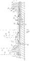
- the track superstructure is constructed in a conventional manner, namely from an HGT layer (hydraulically bound base layer) 10 on an anti-freeze layer 12 and a continuous support plate 14 applied to the HGT layer 10 using slip formwork technology with reinforcement indicated in FIG. 1 Longitudinal bars 16 and transverse bars 18.
- the two rails 20 are connected directly to the support plate 14, namely via a conventional fastening device (type IOARV 300), not shown, and with lateral support on inclined side surfaces 22 of a corresponding continuous recess in the support plate 14.
- the aforementioned fastening is already in itself known for connecting the rail 20 with a separate threshold.
- Fig. 1 left half is indicated by broken lines the outline of a wheel 24 rolling on the rail 20 and the outline of an associated vehicle of the newer type with the vehicle floor 28 pulled down below the wheel axle 26.
- This encapsulation of most of the undercarriage is already achieved a certain noise reduction.
- a soundproofing cheek 30 is now built up on the side of the support plate 14, preferably on both sides, which extends the said contact area between the rail 20 and wheel 24 laterally to the outside covers at least so far that at most a small amount of sound can penetrate directly between the soundproof wall 30 and the lower longitudinal edge 29 of the vehicle.
- the approximately L-shaped soundproof cheek 30 in the cross section of FIG. 1 ends at a height distance a of about 35 cm above the top of the rails 20.
- the cheek head 32 is laterally opposite the side wall 31 of the vehicle offset on the outside, possibly in adaptation to a lower curved edge area of the side wall 31.
- the soundproofing beam 30 does not penetrate into the predetermined so-called clearance profile, which must be kept free of internals for safety reasons (dash-dot-dot line 33 in FIG. 1) ).
- the dewatering channel 64 serves to dewater the inner area that is laterally delimited by the soundproofing cheek 30.
- the soundproofing cheek 30 has a side surface 34 which is concavely curved toward the rail 20 and towards the impeller 26 and which is preferably cylindrically curved with a radius of curvature b of preferably approximately 60 cm.
- a sound-absorbing covering 36 applied with a covering thickness c of preferably 6 to 8 cm.
- Said cheek head 32 adjoins the upper longitudinal edge of the side surface 34 and projects over the side surface 34 in accordance with the covering thickness c. This projection thus covers the covering 36 upwards in order to protect the covering 36 from the weather and mechanical damage.
- the opposite side surface 38 is slightly inclined with respect to the vertical plane.
- a cable receiving channel 40 can be integrally formed, in particular by shaping a correspondingly L-shaped cross-section.
- the cable duct 40 serves to accommodate the usual supply and control lines 42 running along the rail paths. After the cables have been laid, the cable duct 40 is closed by a suitable cover 44.
- a further soundproofing cheek 30 ' is indicated on the right in FIG. 1. This serves simultaneously for sound insulation in the area of the track pair shown, as well as for sound insulation in the area of a track pair, not shown, which adjoins on the right in FIG. 1. Due to the corresponding small transverse distance between the two pairs of tracks, the soundproofing cheek 30 'is formed on both sides with the concavely curved side surface 34', each provided with the corresponding covering 36 '.
- the sound-absorbing covering 36 can, as shown in FIG. 1, extend beyond the respective end of the side surface 34 into the area of the rail fastening of the support plate 14.
- the respective side surface 34 merges into a corresponding contact surface 46 of the continuous support plate 14.
- the sound-absorbing covering 34 can also be applied between the rail fastening areas on the continuous support plate 14, as can also be seen from FIG. 1.
- the cable receiving channel 40 can also be formed simultaneously with the side cheek 30.
- the soundproofing cheek can be built onto the prefabricated support plate 14 immediately laterally on the HGT layer 10.
- both components can be connected to one another by means of conventional anchors 47 in the area of the vertical separation joint 52.
- the soundproofing cheek 30 ' can alternatively also be constructed on the support plate 14 which is correspondingly wider to be produced, so that a horizontal parting line results.
- the described construction prevents direct sound radiation of the sound generated in the area of the rail 20 and wheel 24 laterally outwards.
- the sound-absorbing covering ensures that high noise levels do not even occur between the underside of the vehicle and the track superstructure, which in turn ensures a significant reduction in noise both on the side of the railroad and in the respective vehicle.
- the manufacturing costs for the sound absorber are low, especially if slipform pavers for the production of the respective side cheek and, if necessary, also subsequently for the production of the sound-absorbing covering. These pavers can run on the carrier plate that has already been manufactured, if necessary using appropriate track bogies. It is then not necessary to provide a lane on the HGT layer 10 or the subgrade next to the support plate and the soundproofing beam for the corresponding chassis of the paver.
- FIG. 2 again shows a simplified sectional view of a sound absorber construction similar to FIG. 1, but only for a single pair of rails and with a trough-like continuous support plate (corresponding to European patent specification 0 379 148 D1).
- Components which correspond to those in FIG. 1 in terms of their function are provided with the same reference numbers, but with the number 100 increasing.
- the trough-shaped, continuous support plate 114 including reinforcement made of cross bars 118 and longitudinal bars 116.
- a track grate made of sleepers 160 and the two rails 120 with pouring concrete 162 is cast into the trough-shaped support plate 114.
- a soundproofing cheek 130 is formed on both sides of the support plate 114 and laterally afterwards (corresponding to FIG. 1, left half). Both side walls are in turn provided with sound-absorbing covering 134.
- Anchors 147 ensure the mutual connection of support plate 114 and side wall 130.
- the drainage of the area between the sound absorption cheeks 130 is shown in FIG. 2 by the dewatering channels 164 indicated by the broken lines, which lead laterally outwards from the level above the pouring concrete 162.
- Fig. 3 shows a further variant with two pairs of tracks and sleepers resting on a continuous support plate and supporting the rails.
- Components that function according to those in 2 and FIG. 1 correspond, are provided with the same reference numerals, but increased by the number 100 and 200 respectively.
- the sleepers thus designated with 260 are fastened in the area of their longitudinal center with a fastening device 270 (not shown in detail) to the continuous support plate 214 previously produced. They carry the two rails 220 on which the wheels 224 of the vehicle 231 indicated in outline roll. The wheels 224 only protrude slightly below the underside 272 of the vehicle 231. In Fig. 3 on the left with the line 233 the clearance profile is also indicated.
- the double-sided soundproofing beam 30 'according to FIG. 1 on the right is replaced by two separate soundproofing beams 230. These correspond in structure to the external soundproofing beam.
- the space between the two inner soundproof walls 230 is filled, in particular with floor material 274, in order to ensure an essentially smooth, continuous surface.
- the continuous support plate can also be an asphalt plate, just as the soundproofing beam can be formed not only from reinforced concrete, if necessary, but also from asphalt or similar material. Under certain circumstances, the soundproofing covering can also be omitted.
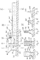
- a soundproofing beam 300 with the aid of a special slipform paver 302 is explained below with reference to FIGS. 4-13.
- This is suitable for the installation of porous building materials, especially aggregate-like cement-bound building materials, which are characterized by their particularly high sound absorption capacity.
- These are building materials with a high proportion of pores, in particular 20% to 40%, preferably about 30%.
- Such a high proportion of pores is easily achieved by a special grain size, namely by a grain with a small diameter variation, in particular of ⁇ 1 mm.
- a mean grain size of 4 mm ( grain size 3/5 mm), ie with a maximum grain size of 5 mm and without grain parts below 3 mm in diameter, is particularly preferred.
- Other possible grain sizes are 3/6 mm or 4/6 mm.
- the building material is installed in two layers.
- a building material supply chamber which widens upwards in the manner of a funnel is divided by a transverse wall 314, the lower edge 316 of which is at a distance a defining the thickness of the first layer from the surface 318 of the substrate 320.
- the transverse wall 314 is beveled with its lower edge region 314a in the direction opposite to direction A, in particular rounded.
- the inclination of the lower edge region 314a can be adjustable relative to the vertical direction for optional adaptation to the respective conditions, in particular to the consistency of the building material used in each case.
- the transverse wall 314 therefore divides the building material supply chamber 312 into a front partial chamber 312a and a rear partial chamber 312b. Building materials are supplied to both chambers via the material distribution device 380, which will be explained below with reference to FIG. 12. Therefore, another layer 322b is automatically used up on the layer 322a leaving the front partial chamber 312a by correspondingly advancing the building material 322 of the rear partial chamber 312b, and is fed to the outlet end 326 of the rear formwork part 310 in accordance with the forward movement of the slipform paver 302 in direction A.
- the cross section of the front formwork part 306 in the direction of the outlet end 326 becomes increasingly the desired, final cross-sectional shape Sound insulation cheek 300 approximated (see Fig. 5-7 and 9).
- the cross section of the soundproof cheek 300 tapers upwards in order to end in a horizontal narrow surface 332. This surface is formed by a ceiling wall 334 connecting the two side walls 328 and 330 in the region of the outlet end 326.
- the front ceiling wall 334 (i.e. in direction A) is arranged with a compression device in the form of a ram 336 which can be moved vertically up and down. This in turn is preceded by a metering slide 338, which is located at the rear end in relation to the direction A of the building material supply chamber 312 which is expanded in a funnel-like manner (more precisely the rear partial chamber 312b).
- the metering slide is vertically movable in a manner not shown; its underside can be bevelled; it can be designed to be adjustable in height and / or incline in order to ensure a finely metered supply of material into the all-round closed end region 340 of the front formwork part 306.
- the rear formwork part 310 is connected to the front formwork part 306 via coupling elements in the form of rubber elements 342 shown in more detail in FIG. 13.
- rubber elements 342 shown in more detail in FIG. 13.
- one of these rubber elements (rubber sleeves) 342 connects one of the side walls 328 (or 330) of the front formwork part 306 with its associated side wall 344 (or 346) of the rear formwork part 310.
- the corresponding side walls z. B. 328 and 344 shown in FIG. 13 formed retaining profile rails 348 in corresponding vertical grooves 350 on the outer side 352 of the rubber element 342 facing away from the building material 322.
- the inner side 354 of the respective rubber element 342 is flush with the respective inner side 356 or 358 of the side wall 328 or 344.
- the rubber element 342 which is made of rubber or similar flexible material, transmits essentially no vibration from the front formwork part 306 to the rear formwork part 310 the two formwork parts 306 and 310 formed Joints on both sides of the building material 322 are sealed by the two rubber elements 342.
- the two side walls 344 and 346 of the rear formwork part 310 can be connected to one another by means of crossbars 360 indicated in FIGS. 4 and 8.
- the rear formwork part 310 is open at the top, so that the narrow surface 332 can still be reworked by hand if necessary.
- early quality control of the soundproofing beam 300 is possible.
- the soundproofing cheek 330 is formed laterally on a continuous support plate 362, resting on an HGT layer 364. Accordingly, the left side wall 330 and 346 of the two formwork parts in FIGS. 5-8 ends 306 and 310 in the area of the corresponding edge 366 of the support plate 362.
- the soundproof cheek 300 has an approximately L-shape with a horizontal leg ending on the support plate 362.
- the inner region of the L cross-sectional shape is preferably curved approximately inwards in a cylindrical manner.
- the circular arc essentially ends in the edge 366 (see also FIG. 11).
- FIGS. 10 and 11 The general structure of the slipform paver 302 is shown in FIGS. 10 and 11.
- a chassis frame 368 can be seen, each with a caterpillar track 370 on the side in the exemplary embodiment shown and at least four rail wheels 372 with a flange.
- the slipform paver 302 travels with the crawler tracks 370 on the rails 374, which are anchored in associated recesses 376 of the support plate 362 via fastening means, not shown.
- the rail wheels 372 with their flanges are used only for directional control.
- the crawler tracks 370 can be adjusted in height in a manner not shown relative to the rail wheels 372.
- the rail wheels 372 disengage from the rails 374, so that the slipform paver 302 outside the Rail area on the crawler tracks 370 can drive.
- the slipform paver 302 is supported on the rails 374 exclusively via the four rail running wheels 372 and can thus be pulled on the rails. In this position, transport over longer distances is possible.
- This mode of operation enables the generally very precisely adjusted rails 374 to be used as a reference for the height and lateral position of the noise barriers to be installed in the form of the noise barriers 300.
- the soundproof cheeks 300 can easily be made so high that they protrude beyond the underside of the rail vehicles for effective noise control, as has already been explained with reference to FIGS. 1-3.
- the manufacturing costs are low at a high manufacturing speed, especially since the slipform paver 302 can be used to manufacture two lateral noise barriers 300 at the same time.
- the slipform paver 302 is formed on both sides with a slipform 304 each consisting of a front formwork part 306 and a rear formwork part 310.
- a swivel arm 388 with a vertical axis of rotation 390 is provided at the respective discharge end of the conveyor belts 382a and b, which can be pivoted alternately in the direction of the double arrow B from its pure transverse position shown in FIG. 12 by adjusting means (not shown).
- adjusting means not shown.
- an optionally height-adjustable main frame 392 is held on chassis frame 368.
- the main frame 392 in turn carries the material distribution device 380 already described. It also carries at least one formwork frame 394 on both sides.
- the two swivel arms 388 are held via corresponding bearing forks 396; on the other hand, they carry the two sliding formworks 304 on both sides of the paver 302, wherein coupling elements 398 indicated in FIG. 11 can be interposed for vibration decoupling, in particular in the form of springs or rubber elements.
- the main frame 392 is connected to the two formwork frames 394 by inclined connecting bars 400 indicated in FIG. 11. In this way, the main frame 392 is kept free from the vibrations generated by the vibrators 308. In addition, vibration transmission to the rear formwork part 310 is also avoided, provided that the rear formwork part is also held on the formwork frame 394 in a manner not shown (in addition to the coupling via the coupling elements 342), preferably also via vibration-damping coupling elements.
- the soundproofing beam (or the two soundproofing beams) can also be manufactured on the side of a conventional ballast bed with track grating, although production at the same time or subsequent to the production of a continuous support plate (also with slipform paver) is particularly preferred.
- a large number of cross-sectional shapes are possible for the soundproofing cheek, and additional elements, such as a cable duct 40 (see FIG. 1), can also be molded on. Since the material (bulk concrete) of the soundproofing beam itself is sound-absorbing, there is usually no need to apply an additional sound-absorbing layer.
Abstract
Description
Die Erfindung betrifft eine Schallabsorberkonstruktion für eine feste Fahrbahn für gleisgebundene Fahrzeuge.The invention relates to a sound absorber construction for a solid carriageway for track-bound vehicles.
Gleisgebundene Verkehrsmittel gewinnen aufgrund ihrer Umweltfreundlichkeit und der bereits erzielten und noch zu erwartenden Geschwindigkeitserhöhung zunehmend an Bedeutung. Mit zunehmender Frequenz und vor allem mit zunehmender Geschwindigkeit wächst jedoch auch die Lärmbelastung durch den Schienenverkehr.Track-bound modes of transport are becoming increasingly important due to their environmental friendliness and the speed increase already achieved and still to be expected. With increasing frequency and above all with increasing speed, however, the noise pollution caused by rail traffic also increases.
Aus der GB-A-2 236 343 ist eine Schallabsorberkonstruktion für eine feste Fahrbahn für gleisgebundene Fahrzeuge bekannt, umfassend eine seitlich des Schienenpaars angeordnete durchgehende Betonwange, die sich über das Schienenniveau hinaus bis in einen Bereich seitlich und oberhalb der Unterseite des Fahrzeugs erstreckt. Die Betonwangen sind hierbei jeweils trogartige Fertigteilelemente, in die die Schwellen des Gleisrostes eingelegt werden. Herstellung und Montage dieser voluminösen und dementsprechend gewichtigen Fertigteile ist aufwendig.From GB-A-2 236 343 a sound absorber construction for a solid carriageway for track-bound vehicles is known, comprising a continuous concrete cheek arranged on the side of the pair of rails, which extends beyond the rail level into an area to the side and above the underside of the vehicle. The concrete cheeks are each trough-like prefabricated elements into which the sleepers of the track grate are inserted. Manufacture and assembly of these voluminous and accordingly weighty finished parts is complex.
Aus der DE-A-41 00 881 ist es bekannt, den Gleisrost in eine Schotterbettung innerhalb eines Trogs wiederum aus Beton-Fertigteilen einzusetzen. Auf den Oberrändern der beiden Trogseitenwangen können Schallschluckplatten befestigt werden. Um eine einfache Handhabung dieser Schallschutzplatte sicherzustellen, sind diese vergleichsweise dünnwandig ausgebildet. Darunter leidet jedoch der Lärmschutz.From DE-A-41 00 881 it is known to use the track grate in a ballast bed within a trough in turn made of prefabricated concrete parts. Sound absorption panels can be attached to the upper edges of the two side walls of the trough. In order to ensure easy handling of this soundproofing plate, these are comparatively thin-walled. However, noise protection suffers from this.
Der Erfindung liegt die Aufgabe zugrunde, eine Schallabsorberkonstruktion bereitzustellen, die bei gutem Schallschutz einfach herstellbar ist.The invention has for its object to provide a sound absorber construction that is easy to manufacture with good sound insulation.
Diese Aufgabe wird dadurch gelöst, daß die Schallschutzwange mittels Gleitschalungsfertiger aus Beton oder Asphalt gefertigt ist. Die Schallschutzwange kann somit schnell und kostengünstig und bei Bedarf auch kontinuierlich entsprechend dem Baufortschritt hergestellt werden. Dabei können auch große Querschnittsabmessungen gewählt werden mit entsprechend hohem Schallabsorbtionsvermögen.This object is achieved in that the soundproofing cheek is made of concrete or asphalt by means of slipform pavers. The soundproofing beam can thus be manufactured quickly and inexpensively and, if necessary, continuously according to the construction progress. Large cross-sectional dimensions with a correspondingly high sound absorption capacity can also be selected.
Die erfindungsgemäße Schallabsorberkonstruktion führt somit zu einer wirksamen Fahrgeräuschpegel-Erniedrigung. Die Betonwange deckt den Bereich Schiene - Rad seitlich ab, so daß der direkte Schallweg unterbrochen ist. Dies dämpft die Weitergabe des Schalls seitlich nach außen hin. Bei neueren Schienenfahrzeugen ist der Unterboden des Fahrzeugs über die Radachsen nach unten verlagert, um auf diese Weise eine weitgehende Einkapselung der Räder zu erhalten. Dementsprechend reicht es aus, wenn die Schallschutzwange die Oberseite der Schiene um 25 bis 40 cm, vorzugsweise 30 bis 35 cm überragt, um hierdurch das Fahrzeug seitlich teilweise und mit ausreichendem Sicherheitsabstand zu umgreifen.The sound absorber construction according to the invention thus leads to an effective reduction in driving noise level. The concrete cheek covers the area of the rail and wheel from the side, so that the direct sound path is interrupted. This dampens the transmission of the sound to the outside. In newer rail vehicles, the underbody of the vehicle is shifted downward over the wheel axles in order to obtain an extensive encapsulation of the wheels. Accordingly, it is sufficient if the soundproofing cheek protrudes 25 to 40 cm, preferably 30 to 35 cm, above the top of the rail in order thereby to encompass the vehicle partially and with a sufficient safety distance.
Besonders bevorzugt ist die Schallschutzwange mit einer zur Schiene und zum Laufrad hin konkav gewölbten Seitenfläche ausgebildet. Dies hat den Vorteil, daß von Schiene und Rad emittierte Schallschwingungen stärker zurückreflektiert als seitlich nach außen hin abgelenkt werden, was die seitliche Schallabstrahlung wiederum reduziert. Auch kann die Wange bei entsprechend gewölbtem Fahrzeug näher an das Fahrzeug herangeführt werden, mit dementsprechend reduziertem Schallaustrittsspalt zwischen Wange und Fahrzeug.The soundproofing cheek is particularly preferably designed with a side surface that is concavely curved toward the rail and the impeller. This has the advantage that sound vibrations emitted by the rail and wheel are reflected back to a greater extent than are deflected laterally outwards, which in turn reduces the lateral sound radiation. The cheek can also be brought closer to the vehicle with a correspondingly curved vehicle, with a correspondingly reduced sound outlet gap between the cheek and the vehicle.
Als vorteilhaft hat sich hierbei eine im wesentlichen zylindrisch gewölbte Seitenfläche herausgestellt mit einem Krümmungsradius vorzugsweise zwischen 35 und 150 cm, besser 40 bis 80 cm, am besten etwa von 60 cm.An essentially cylindrically curved side surface with a radius of curvature has proven advantageous here preferably between 35 and 150 cm, more preferably 40 to 80 cm, preferably about 60 cm.
Gemäß einer besonders bevorzugten Ausführungsform der Erfindung ist vorgesehen, daß die Schallschutzwange zumindest an ihrer der Schiene und dem Laufrad zugewandten Seitenfläche mit einem schallabsorbierenden Belag versehen ist. Der schallabsorbierende Belag sorgt für eine Reduzierung des Schallpegels zwischen Schallabsorber und Fahrzeug. Die seitlich abgestrahlte Schallintensität wird dementsprechend reduziert, wie auch der im Fahrzeug selbst wahrnehmbare Schallpegel. Für den schallabsorbierenden Belag kommen viele Materialien in Frage, wie Hartschaummaterialien oder Textilmaterialien oder auch Kautschukmaterialien. Als besonders günstig hat sich der Einsatz von offenporigen Schaumglaskugeln herausgestellt, die mittels Bindemittel offenporig zusammengehalten werden. (Auch kommt poriger Baustoff, wie Haufwerksbeton in Frage, wobei dann besonders bevorzugt die gesamte Schallschutzwange aus diesem Baustoff hergestellt wird, so daß sich die Herstellung dementsprechend vereinfacht).According to a particularly preferred embodiment of the invention, it is provided that the soundproofing cheek is provided with a sound-absorbing covering at least on its side surface facing the rail and the impeller. The sound-absorbing covering reduces the sound level between the sound absorber and the vehicle. The sound intensity emitted from the side is reduced accordingly, as is the sound level perceptible in the vehicle itself. Many materials are suitable for the sound-absorbing covering, such as rigid foam materials or textile materials or rubber materials. The use of open-pore foam glass spheres, which are held together by open-pore binders, has proven to be particularly favorable. (Also porous building material, such as bulk concrete, comes into question, in which case the entire soundproofing cheek is particularly preferably produced from this building material, so that the production is accordingly simplified).
Bei einem derartigen Material beträgt die Belagdecke bevorzugt 8 bis 10 cm, besser 6 bis 8 cm.With such a material, the covering ceiling is preferably 8 to 10 cm, more preferably 6 to 8 cm.
Als mechanischer Schutz für den schallabsorbierenden Belag sowie als Witterungsschutz dient ein sich an den oberen Längsrand der gewölbten Seitenfläche anschließender entsprechend der Belagdicke vorspringender Wangenkopf.Mechanical cheek protection for the sound-absorbing covering and weather protection is provided by a cheek head that protrudes from the upper longitudinal edge of the curved side surface in accordance with the thickness of the covering.
Um die Schallabsorptionswirkung weiter zu verbessern, wird vorgeschlagen, daß sich der schallabsorbierende Belag bis in den Befestigungsbereich der Schiene und vorzugsweise auch im Bereich zwischen den Schienen erstreckt.In order to further improve the sound absorption effect, it is proposed that the sound absorbing covering extend into the fastening area of the rail and preferably also in the area between the rails.
Um eine beidseitige Lärmabschirmung zu erreichen, ist bevorzugt jeweils an beiden Seiten eines Schienenpaares eine durchlaufende Betonwange vorgesehen. Wenn zwei oder mehrere Schienenpaare nebeneinander liegen, können die beiden Betonwangen zwischen zwei aufeinanderfolgenden Schienenpaaren je nach Abstand zwischen beiden Schienenpaaren als gesonderte Betonwangen ausgebildet sein oder zu einer einzigen Betonwange integriert sein, wobei diese dann beidseitig mit konkav gewölbten Seitenflächen ausgebildet ist. Für den Fall separater Schallschutzwangen wird der Zwischenraum zwischen beiden bevorzugt aufgefüllt, vorzugsweise mit Bodenmaterial.In order to achieve noise shielding on both sides, a continuous concrete cheek is preferably provided on both sides of a pair of rails. If two or more pairs of rails lying side by side, the two concrete cheeks between two successive pairs of rails can be designed as separate concrete cheeks, depending on the distance between the two pairs of rails, or can be integrated into a single concrete cheek, which is then formed on both sides with concave curved side surfaces. In the case of separate soundproof walls, the space between the two is preferably filled, preferably with floor material.
Als Ersatz für die bisher üblichen gesonderten Kabelkanäle seitlich der Schienen wird vorgeschlagen, daß wenigstens eine der schallabsorbierenden Wangen integral mit einem Kabelaufnahmekanal ausgebildet ist. Dadurch ergeben sich deutlich reduzierte Hersteller- und Verlegekosten.As a replacement for the previously customary separate cable channels on the side of the rails, it is proposed that at least one of the sound-absorbing cheeks be formed integrally with a cable receiving channel. This results in significantly reduced manufacturer and installation costs.
Die Schallschutzwange kann sich seitlich an eine durchgehende Tragplatte anschließen. Alternativ kann die Schallschutzwange auch auf der durchgehenden Tragplatte aufliegen. Vor allem im ersteren Fall wird die Schallschutzwange mit der Tragplatte über Anker verbunden.The sound insulation cheek can connect to a continuous support plate on the side. As an alternative, the soundproofing beam can also rest on the continuous support plate. Especially in the former case, the soundproofing beam is connected to the support plate via anchors.
Bevorzugt vorgesehene Entwässerungsdurchgänge in der Schallschutzwange und/oder auf der durchgehenden Tragplatte sorgen für ausreichende Entwässerung.Preferred drainage passages in the soundproofing cheek and / or on the continuous support plate ensure adequate drainage.
Um bei einem Fahrleitungsbruch eine Gefährdung durch die abhängende Fahrleitung wesentlich zu vermindern, wird vorgeschlagen, daß an der Schallschutzwange ein geerdeter Leiter angeordnet ist, vorzugsweise am Wangenkopf. Bevorzugt ist der Leiter ein Blitzableiterdraht.In order to significantly reduce the danger from the overhead contact line in the event of a catenary breakage, it is proposed that an earthed conductor be arranged on the soundproofing cheek, preferably on the cheek head. The conductor is preferably a lightning rod.
Auch der schallabsorbierende Belag kann mittels Gleitschalungsfertiger auf die bereits vorher hergestellte Schallschutzwange aufgebracht werden.The sound-absorbing covering can also be applied to the previously made soundproofing beam using slipform pavers.
Für den Schallabsorber kommt bevorzugt ein gebundenes Blähglasgranulat in Frage. Daneben kommt aber auch gebundenes Blähtongranulat in Frage, wie auch Haufwerksbeton.A bonded expanded glass granulate is preferred for the sound absorber. In addition, bound expanded clay granulate can also be used, as can bulk concrete.
Die Erfindung betrifft auch ein Verfahren zur Herstellung einer seitlich an der Schiene angeordneten durchgehenden Schallschutzwange einer festen Fahrbahn für gleisgebundene Fahrzeuge, welches dadurch gekennzeichnet ist, daß man die Schallschutzwange mittels eines bevorzugterweise schienengängigen Gleitschalungsfertigers fertigt, vorzugsweise anschließend an die Fertigung einer durchgehenden Tragplatte. Anschließend kann man den schallabsorbierenden Belag mittels Gleitschalungsfertiger an die Schallschutzwange anformen.The invention also relates to a method for producing a continuous soundproofing cheek of a fixed carriageway for track-bound vehicles arranged on the side of the rail, which is characterized in that the soundproofing cheek is manufactured by means of a preferably slipform paver which can be passed through rails, preferably subsequent to the production of a continuous support plate. The sound-absorbing covering can then be molded onto the soundproof wall using a slipform paver.
Als besonders vorteilhaft für hohen Lärmschutz hat sich herausgestellt, die gesamte Schallschutzwange aus einem porigen Baustoff mit einem Porenvolumenanteil von 20 % bis 40 %, vorzugsweise etwa 30 % herzustellen.It has been found to be particularly advantageous for high noise protection to produce the entire soundproofing cheek from a porous building material with a pore volume fraction of 20% to 40%, preferably about 30%.
Besonders bevorzugt wird die Schallschutzwand aus haufwerksartigem, zementgebundenem Baustoff hergestellt, vorzugsweise mit einem Zementanteil von 150 kg bis 300 kg Zement/m3, besser 200 kg bis 300 kg Zement/m3 und vorzugsweise mit Körnung zwischen 2 mm und 5 mm oder zwischen 4 mm und 8 mm.The soundproofing wall is particularly preferably made from a pile-like, cement-bound building material, preferably with a cement content of 150 kg to 300 kg cement / m 3 , more preferably 200 kg to 300 kg cement / m 3 and preferably with a grain size between 2 mm and 5 mm or between 4 mm and 8 mm.
Um den Zusammenhalt des Baustoffs nach Verlassen des Gleitschalungsfertigers und vor Verfestigung des Betonanteils zu verbessern, wird vorgeschlagen, einen Baustoff mit einem reduziertem Wassergehalt von 35 bis 45, vorzugsweise etwa 40 Gewichtsprozent bezogen auf das Zementgewicht einzusetzen und/oder mit einem Zusatz von Bentonit, Mikrosilika und/oder von wasserlöslichen Polymeren, vorzugsweise Polyethylenoxid.In order to improve the cohesion of the building material after leaving the slipform paver and before the concrete portion has solidified, it is proposed to use a building material with a reduced water content of 35 to 45, preferably about 40 percent by weight based on the cement weight and / or with an addition of bentonite, microsilica and / or of water-soluble polymers, preferably polyethylene oxide.
Die Erfindung betrifft ferner einen Gleitschalungsfertiger zur Fertigung von Bauwerken, insbesondere Schallabsorberkonstruktionen der vorstehend beschriebenen Art, aus porigen Baustoffen, insbesondere haufswerkartigen, zementgebundenen Baustoffen, umfassend eine Gleitschalung mit zwei gesonderten Schalungsteilen, von denen einer einen in Fertigungsrichtung vorderen Abschnitt der Gleitschalung bildet und durch wenigstens eine Rütteleinrichtung in Vibration versetzbar ist, und von denen der andere einen in Fertigungsrichtung hinteren Abschnitt der Gleitschaltung bildet und vom vorderen Abschnitt derart mechanisch entkoppelt ist, daß die Vibrationen des vorderen Schalungsteils im wesentlichen nicht auf den hinteren Schalungsteil übertragen werden.The invention further relates to a slipform paver for the manufacture of buildings, in particular sound absorber constructions of the type described above, from porous building materials, in particular heap-like, cement-bound building materials. comprising a sliding formwork with two separate formwork parts, one of which forms a front section of the sliding formwork in the production direction and can be set in vibration by at least one vibrating device, and of which the other forms a rear section of the sliding circuit in the production direction and is mechanically decoupled from the front section that the vibrations of the front formwork part are essentially not transmitted to the rear formwork part.
Die Herstellung von Bauwerken aus porigen Baustoffen, insbesonder haufwerksartigen Baustoffen in Gleitschalungstechnik, wurde bislang für unmöglich gehalten. Dies liegt daran, daß bei den bekannten Gleitschalungsfertigern die Verdichtung und Formanpassung an die Gleitschalung mit Hilfe von Innenrüttlern und sich im wesentlichen über die gesamte Oberfläche erstreckenden vibrierenden Gleitbohlen erfolgt. Damit lassen sich Baustoffe einbauen, die sich durch eine bei Null beginnende stetige Körnungslinie und einen geringen Porenanteil im Bereich zwischen 0 % und 5 % im verdichteten Zustand auszeichnen, da in diesem Material beim Verdichten durch Vibration Wasserdruck in den Poren aufgebaut wird, so daß sich die Vibrationen ausgehend von den Innenrüttlern über den gesamten Querschnitt ausbreiten. Bei porigem Baustoff dagegen beschränken sich die Vibrationen unmittelbar auf den Bereich um den Innenrüttler, da das mit einem hohen Anteil von Luftporen versehene Material rund um den Rüttler entsprechend nachgiebig und somit vibrationsdämpfend ist.The production of structures from porous building materials, in particular pebble-like building materials using slipform technology, was previously considered impossible. This is because, in the known slipform pavers, the compaction and shape adaptation to the slipforming is carried out with the help of internal vibrators and vibrating screeds which extend essentially over the entire surface. This allows building materials to be built in which are characterized by a steady grain line starting at zero and a low pore content in the range between 0% and 5% in the compacted state, since water pressure builds up in the pores when compacted by vibration, so that spread the vibrations from the internal vibrators over the entire cross-section. In the case of porous building materials, on the other hand, the vibrations are limited to the area around the internal vibrator, since the material with a high proportion of air pores around the vibrator is correspondingly flexible and therefore vibration-damping.
Mit dem erfindungsgemäßen Gleitschalungsfertiger ist es erstmals möglich, porige Baustoffe, insbesondere haufwerksartige, zementgebundene Baustoffe in Gleitschalungstechnik zu fertigen. Erfindungsgemäß wird der gesamte vordere Abschnitt der Gleitschalung in Vibration versetzt, so daß es aufgrund der großflächigen Angriffs der Vibrationskraft zu einer ausreichenden Vibration des Materials über einen größeren Materialbereich kommt und eine ausreichende Verformbarkeit und Verdichtung gewährleistet ist. Diese Vibration des Materials, zumindest über einen wesentlichen Teil des Querschnitts, führt jedoch dazu, daß das Material beim Verlassen des vibrierenden vorderen Abschnitts der Gleitschalung in sich nicht ausreichend stabil ist, um seine aufgeprägte Form beizubehalten. Der erfindungsgemäß auf den vorderen vibrierenden Schalungsteil folgende hintere Schalungsteil, der von den Vibrationen des vorderen Schalungsteils entkoppelt ist und damit selbst nicht vibriert, hält den Baustoff zwischen sich weiterhin in der gewünschten Querschnittsform. Das Material beruhigt sich und die innere Reibung wächst dementsprechend an. Beim Verlassen des hinteren Schalungsteils weist der Baustoff somit ausreichenden Zusammenhalt auf.With the slipform paver according to the invention, it is possible for the first time to manufacture porous building materials, in particular heap-like, cement-bound building materials using slipforming technology. According to the invention, the entire front section of the sliding formwork is set in vibration, so that due to the large-scale attack of the vibrating force there is sufficient vibration of the material over a larger area of material and sufficient deformability and compression is guaranteed. However, this vibration of the material, at least over a substantial part of the cross-section, leads to the fact that the material is not sufficiently stable in itself when leaving the vibrating front section of the sliding formwork in order to maintain its impressed shape. The rear formwork part following the front vibrating formwork part according to the invention, which is decoupled from the vibrations of the front formwork part and thus does not vibrate itself, keeps the building material between them in the desired cross-sectional shape. The material calms down and the internal friction increases accordingly. When leaving the rear formwork part, the building material is sufficiently cohesive.
Zur Erzielung einer guten Verdichtung erfolgt der Einbau in mindestens zwei Lagen, wozu entsprechend wenigstens zwei Baustoff-Zuführungen vorgesehen sind. Dies reduziert den jeweiligen Einbauquerschnitt, der dementsprechend leichter durch Vibrationen zu formen und zu verdichten ist.To achieve good compaction, it is installed in at least two layers, for which purpose at least two building material feeds are provided. This reduces the respective installation cross-section, which is accordingly easier to shape and compress through vibrations.
Zur Realisierung dieser wenigstens zwei Baustoff-Zuführungen kann eine Baustoff-Zuführkammer im Bereich des vorderen Schalungsteils vorgesehen sein, die durch wenigstens eine Querwand in Teilkammern unterteilt ist, wobei die unteren Ränder der Querwände in zur Fertigungsrichtung entgegengesetzter Richtung zunehmenden Abstand zu der durch die unteren Ränder der Gleitschalung festgelegten Untergrundebene aufweisen. Um das Material bei der Vorwärtsbewegung der Gleitschalung zwangsläufig in die Schalungsform zu pressen und zu verdichten, ist vorgesehen, daß die wenigstens eine Querwand in einem unteren Bereich in zur Fertigungsrichtung entgegengesetzter Richtung abgeschrägt ausgebildet ist. Es wird weiterhin vorgeschlagen, den unteren Bereich so auszubilden, daß sein Neigungswinkel wahlweise verstellt werden kann, um so das Herstellungsverfahren zu optimieren.To implement these at least two building material feeds, a building material feed chamber can be provided in the area of the front formwork part, which is subdivided into subchambers by at least one transverse wall, the lower edges of the transverse walls increasing in the opposite direction to the production direction from the distance through the lower edges of the slipform have a defined sub-level. In order to inevitably press and compact the material into the form of the form during the forward movement of the sliding formwork, it is provided that the at least one transverse wall is bevelled in a lower region in the direction opposite to the production direction. It is further proposed to design the lower area so that its angle of inclination can be optionally adjusted so as to optimize the manufacturing process.
Zur zusätzlichen Verdichtung des Bauwerks, insbesondere im Falle eines sich nach oben verjüngenden Bauwerks, wird vorgeschlagen, daß der vordere Schalungsteil vorzugsweise in einem in Fertigungsrichtung hinteren Endbereich der Baustoff-Zuführkammer mit einem Verdichtungselement, vorzugsweise Stampfer oder Rüttelplatte, versehen ist, vorzugsweise zur Verdichtung lediglich einer im wesentlichen horizontalen Schmalfläche des sich nach oben verjüngenden Bauwerks.For additional compaction of the structure, in particular in the case of a structure tapering upwards, it is proposed that the front formwork part is preferably provided with a compaction element, preferably a tamper or vibrating plate, in a rear end region of the construction material supply chamber in the direction of production, preferably only for compaction an essentially horizontal narrow surface of the structure tapering upwards.
Um eine gleichmäßige Oberflächenverdichtung mit Hilfe des Verdichtungselements zu erreichen, wird vorgeschlagen, daß dem Verriegelungselement ein Dosierelement, vorzugsweise Dosierschieber, vorgelagert ist. Der Dosierschieber kann an seiner Unterseite abgeschrägt und in der Höhe und/oder der Neigung verstellbar sein.In order to achieve a uniform surface compaction with the aid of the compaction element, it is proposed that the locking element be preceded by a metering element, preferably a metering slide. The metering slide can be chamfered on its underside and adjustable in height and / or inclination.
Zur Halterung der Schalungsteile kann ein Hauptrahmen sowie ein die Schalungsteile halternder, vom Hauptrahmen getragener Schalungsrahmen vorgesehen sein.A main frame and a formwork frame holding the formwork parts and carried by the main frame can be provided to hold the formwork parts.
Um eine Vibrationsübertragung auf den Hauptrahmen und damit auf den hinteren Schalungsteil weitestgehend auszuschließen, wird vorgeschlagen, daß die Schalungsteile über Vibrationsdämpfer mit dem Schalungsrahmen verbunden sind. Hierzu dient auch die Maßnahme, das vordere Schalungsteil mit dem hinteren Schalungsteil über schwingungsentkoppelnde Kopplungselemente, insbesondere Gummielemente, miteinander zu verbinden, ggf. unter Abdichtung einer zwischen den Schalungsteilen auftretenden Fuge. Bei diesen Gummielementen kann es sich um Gummimanschetten oder dergleichen handeln. Über die Kopplungselemente kann das hintere Schalungsteil nach Art einer "Schleppschalung" vom vorderen Schalungsteil nachgeschleppt werden.In order to largely rule out the transmission of vibrations to the main frame and thus to the rear formwork part, it is proposed that the formwork parts be connected to the formwork frame via vibration dampers. The measure to connect the front formwork part with the rear formwork part via vibration-decoupling coupling elements, in particular rubber elements, is also used for this purpose, if necessary by sealing a joint that occurs between the formwork parts. These rubber elements can be rubber sleeves or the like. Via the coupling elements, the rear formwork part can be dragged from the front formwork part like a "drag formwork".
Der Hauptrahmen kann mit mindestens zwei Raupenfahrwerken und mindestens vier mit Spurkranz versehenen Schienenrädern versehen sein, wobei die Raupenfahrwerke relativ zu den Schienenrädern höhenverstellbar ausgebildet sind. Durch Absenken der Raupenfahrwerke wird der Fertiger einschließlich der fest eingebauten Schienenräder gehoben, so daß der Fertiger außerhalb des Schienenbereichs auf den Raupenfahrwerken fahren kann. Durch Anheben der Raupenfahrwerke wird erreicht, daß sich der Fertiger ausschließlich auf die vier mit Spurkranz versehenen Schienenräder abstützt und somit auf den Schienen gezogen werden kann. In dieser Stellung sind Transporte auf den Schienenweg über längere Strecken möglich.The main frame can be provided with at least two crawler tracks and at least four rail wheels provided with a wheel flange, the crawler tracks being designed to be height-adjustable relative to the rail wheels. By lowering the The paver, including the permanently installed rail wheels, is raised on the crawler tracks so that the paver can travel on the crawler tracks outside the rail area. By lifting the crawler tracks, the paver is supported only on the four rail wheels with wheel flanges and can thus be pulled on the rails. In this position, rail transport over long distances is possible.
Eine Weiterbildung der Erfindung ist gekennzeichnet durch eine Materialverteileinrichtung mit zwei Förderbändern, die den Baustoff zur gleichzeitigen Fertigung zweier Bauwerke zu quer zur Förderrichtung voneinander beabstandeten Baustoff-Aufnahmekammern fördern. Somit ist die gleichzeitige Fertigung zweier Bauwerke ohne weiteres möglich. Ferner kann vorgesehen sein, daß an den Baustoffzuführkammer-seitigen Enden der beiden Förderbänder jeweils ein Materialverteiler, vorzugsweise Schwenkarm vorgesehen ist zur wahlweisen Verteilung des Materials auf die jeweiligen Teilkammern. Dies ermöglicht eine einfache und leichte Anpassung an die jeweiligen Erfordernisse.A further development of the invention is characterized by a material distribution device with two conveyor belts, which convey the building material for the simultaneous production of two structures to building material receiving chambers spaced apart from one another transversely to the conveying direction. Thus, the simultaneous production of two structures is easily possible. Furthermore, it can be provided that a material distributor, preferably a swivel arm, is provided at the ends of the two conveyor belts on the side of the building material feed chamber for optionally distributing the material to the respective subchambers. This enables simple and easy adaptation to the respective requirements.
Die Erfindung wird im folgenden an bevorzugten Ausführungsbeispielen erläutert. Es zeigt:
- Fig. 1
- eine vereinfachte Querschnittsdarstellung eines Eisenbahnoberbaus mit auf einer durchgehenden Tragplatte unmmittelbar montierten Schienen und mit seitlichen Schallabsorberwangen;
- Fig. 2
- eine Ansicht ähnlich Fig. 1, jedoch mit trogartig ausgebildeter durchgehender Tragplatte und ausgegossenem Gleisrost;
- Fig. 3
-
eine Ansicht wiederum ähnlich den Fig. 1 und 2, jedoch mit zwei Schienenpaaren mit gesonderten Schwellen auf jeweils einer durchgehenden Tragplatte; - Fig. 4
- einen stark vereinfachten Längsschnitt durch einen vorderen und einen hinteren Schalungsteil eines im übrigen nicht dargestellten Gleitschalungsfertigers entsprechend den Fig. 10 und 11;
- Fig. 5-9
- Querschnitte der Anordnung in Fig. 4 entlang der Linien V-V bis IX-IX;
- Fig. 10
- eine stark vereinfachte Seitenansicht des die Schalungsteile gemäß Fig. 4-9 einsetzenden Gleitschalungsfertigers;
- Fig. 11
- eine ebenfalls stark vereinfachte Querschnittsansicht des Gleitschalungsfertigers gemäß Fig. 10 im Schnitt nach Linie XI-XI;
- Fig. 12
- eine vereinfachte Draufsicht auf eine Materialverteileinrichtung sowie auf einen von dieser beschickten vorderen und hinteren Schalungsteil des Gleitschalungsfertigers gemäß Fig. 10 und 11 (Blickrichtungspfeil XII in Figur 11); und
- Fig. 13
- eine vergrößerte Schnittansicht des Details XIII in Fig. 12.
- Fig. 1
- a simplified cross-sectional view of a railway superstructure with rails directly mounted on a continuous support plate and with lateral sound absorber cheeks;
- Fig. 2
- a view similar to Figure 1, but with a trough-shaped continuous support plate and poured track grate.
- Fig. 3
-
a view again similar to Figures 1 and 2, but with two pairs of rails with separate sleepers on a continuous support plate. - Fig. 4
- a greatly simplified longitudinal section through a front and a rear formwork part of an otherwise not shown slipform paver according to FIGS. 10 and 11;
- Fig. 5-9
- Cross sections of the arrangement in Figure 4 along lines VV to IX-IX;
- Fig. 10
- a greatly simplified side view of the slipform paver using the formwork parts according to FIGS. 4-9;
- Fig. 11
- a likewise greatly simplified cross-sectional view of the slipform paver according to FIG 10 in section along line XI-XI.
- Fig. 12
- a simplified plan view of a material distribution device and one of the front and rear formwork part of the slipform paver, which is fed by this, according to FIGS. 10 and 11 (arrow XII in FIG. 11); and
- Fig. 13
- an enlarged sectional view of detail XIII in Fig. 12th
Gemäß Fig. 1 ist der Gleisoberbau in herkömmlicher Weise aufgebaut, nämlich aus einer HGT-Schicht (hydraulisch gebundene Tragschicht) 10 auf einer Frostschutzschicht 12 und einer auf der HGT-Schicht 10 in Gleitschalungstechnik aufgebrachten durchgehenden Tragplatte 14 mit in Fig. 1 angedeuteter Bewehrung aus Längsstäben 16 und Querstäben 18. Die beiden Schienen 20 sind unmittelbar mit der Tragplatte 14 verbunden und zwar über eine übliche, nicht dargestellte Befestigungseinrichtung (Typ IOARV 300) und mit seitlicher Abstützung an geneigten Seitenflächen 22 einer entsprechenden durchgehenden Ausnehmung der Tragplatte 14. Die genannte Befestigung ist an sich bereits zur Verbindung der Schiene 20 mit einer gesonderten Schwelle bekannt.1, the track superstructure is constructed in a conventional manner, namely from an HGT layer (hydraulically bound base layer) 10 on an
In Fig. 1, linke Hälfte ist mit unterbrochenen Linien der Umriß eines an der Schiene 20 abrollenden Rades 24 angedeutet sowie der Umriß eines zugehörigen Fahrzeugs der neueren Bauart mit bis unter die Radachse 26 heruntergezogenem Fahrzeugboden 28. Durch diese Einkapselung des Großteils des Fahrwerks wird bereits eine gewisse Schallreduzierung erreicht. Um auch Schallemissionen zu reduzieren, die aus dem Kontaktbereich zwischen Schiene 20 und Rad 24 stammen, wird nunmehr seitlich der Tragplatte 14, am besten auf beiden Seiten, jeweils eine Schallschutzwange 30 aufgebaut, die den besagten Kontaktbereich zwischen Schiene 20 und Rad 24 seitlich nach außen hin zumindest so weit abdeckt, daß allenfalls ein geringer Schallanteil auf direktem Wege zwischen Schallschutzwange 30 und dem unteren Längsrand 29 des Fahrzeugs nach außen dringen kann.In Fig. 1, left half is indicated by broken lines the outline of a wheel 24 rolling on the
Hierzu endet die im Querschnitt der Fig. 1 angenähert L-förmige Schallschutzwange 30 in einem Höhenabstand a von etwa 35 cm oberhalb der Oberseite der Schienen 20. Um nicht mit dem Fahrzeug zu kollidieren, ist der Wangenkopf 32 gegenüber der Seitenwand 31 des Fahrzeugs seitlich nach außen versetzt, ggf. in Anpassung an einen unteren gewölbten Randbereich der Seitenwand 31. Auf jeden Fall dringt die Schallschutzwange 30 nicht in das vorgegebene sogenannte Lichtraumprofil ein, welches aus Sicherheitsgründen von Einbauten freizuhalten ist (Strich-Punkt-Punkt-Linie 33 in Figur 1).For this purpose, the approximately L-shaped
Der strichliert angedeutete Entwässerungskanal 64 dient der Entwässerung des von der Schallschutzwange 30 seitlich begrenzten inneren Bereiches.The dewatering
Die Schallschutzwange 30 weist eine zur Schiene 20 und zum Laufrad 26 hin konkav gewölbte Seitenfläche 34 auf, die bevorzugt zylindrisch gewölbt ist mit einem Krümmungsradius b von bevorzugt etwa 60 cm. Auf diese Seitenfläche 34 ist ein schallabsorbierender Belag 36 aufgetragen mit einer Belagdicke c von vorzugsweise 6 bis 8 cm. An den oberen Längsrand der Seitenfläche 34 schließt sich der besagte Wangenkopf 32 an, der entsprechend der Belagdicke c über die Seitenfläche 34 vorspringt. Dieser Vorsprung deckt somit den Belag 36 nach oben hin ab, um den Belag 36 vor Witterungseinflüssen und mechanischer Beschädigung zu beschützen.The soundproofing
Die gegenüberliegende Seitenfläche 38 ist geringfügig gegenüber der Vertikalebene geneigt. Im Bereich des unteren Längsrandes der Seitenfläche 38 kann ein Kabelaufnahmekanal 40 integral angeformt sein, insbesondere durch Anformung eines entsprechend im Querschnitt L-förmigen Winkels. Der Kabelkanal 40 dient der Aufnahme der üblichen, längs der Schienenwege verlaufenden Versorgungs- und Steuerleitungen 42. Nach dem Verlegen der Kabel wird der Kabelkanal 40 durch eine geeignete Abdeckung 44 verschlossen.The opposite side surface 38 is slightly inclined with respect to the vertical plane. In the region of the lower longitudinal edge of the side surface 38, a cable receiving channel 40 can be integrally formed, in particular by shaping a correspondingly L-shaped cross-section. The cable duct 40 serves to accommodate the usual supply and
In Fig. 1 rechts ist eine weitere Schallschutzwange 30' angedeutet. Diese dient gleichzeitig zur Schalldämmung im Bereich des dargestellten Gleispaares wie auch zur Schalldämmung im Bereich eines sich in Fig. 1 rechts anschließenden, nicht dargestellten Gleispaares. Aufgrund des entsprechenden geringen Querabstands zwischen beiden Gleispaaren ist die Schallschutzwange 30' beidseits jeweils mit der konkav gewölbten Seitenfläche 34' ausgebildet, jeweils versehen mit dem entsprechenden Belag 36'.A further soundproofing cheek 30 'is indicated on the right in FIG. 1. This serves simultaneously for sound insulation in the area of the track pair shown, as well as for sound insulation in the area of a track pair, not shown, which adjoins on the right in FIG. 1. Due to the corresponding small transverse distance between the two pairs of tracks, the soundproofing cheek 30 'is formed on both sides with the concavely curved side surface 34', each provided with the corresponding covering 36 '.
Was den schallabsorbierenden Belag 36 betrifft, so kann dieser, wie in Fig. 1 dargestellt, sich über das jeweilige Ende der Seitenfläche 34 hinaus bis in den Bereich der Schienenbefestigung der Tragplatte 14 erstrecken. Hierzu geht die jeweilige Seitenfläche 34 über in eine entsprechende Auflagefläche 46 der durchgehenden Tragplatte 14.As far as the sound-absorbing
Auch zwischen den Schienenbefestigungsbereichen auf der durchgehenden Tragplatte 14 kann der schallabsorbierende Belag 34 aufgebracht werden, wie aus Fig. 1 ebenfalls ersichtlich ist.The sound-absorbing
Für den schallabsorbierenden Belag kommen vielfältige Materialien in Frage, wie z. B. Haufwerksbeton oder gebundenes Blähtongranulat.For the sound-absorbing covering, a variety of materials come into question, such as. B. bulk concrete or bound expanded clay granulate.
Nach der Herstellung der Tragplatte 14 mit Hilfe eines entsprechenden Gleitschalungsfertigers werden die Seitenwangen 30 bzw. 30' gefertigt, und zwar bevorzugt mit Hilfe eines entsprechenden Gleitschalungsfertigers, wie dieser nachfolgend anhand der Fig. 4-13 beschrieben wird.After the
Wie in Fig. 1 links angedeutet, kann gleichzeitig mit der Seitenwange 30 auch der Kabelaufnahmekanal 40 ausgeformt werden. Gemäß Fig. 1 links kann die Schallschutzwange an die vorgefertigte Tragplatte 14 unmittelbar seitlich anschließend auf der HGT-Schicht 10 aufgebaut werden. Um den Zusammenhalt von Tragplatte 14 und Schallschutzwange 30 sicherzustellen, können beide Bauteile mittels üblicher Anker 47 im Bereich der Vertikaltrennfuge 52 miteinander verbunden werden.As indicated on the left in FIG. 1, the cable receiving channel 40 can also be formed simultaneously with the
Gemäß Fig. 1 rechts kann die Schallschutzwange 30' auch alternativ auf der dementsprechend breiter zu fertigenden Tragplatte 14 aufgebaut werden, so daß sich eine horizontale Trennfuge ergibt.According to FIG. 1 on the right, the soundproofing cheek 30 'can alternatively also be constructed on the
Durch die beschriebene Konstruktion ist zum einen eine direkte Schallabstrahlung des im Bereich Schiene 20 und Rad 24 erzeugten Schalls seitlich nach außen hin unterbunden. Zum anderen sorgt der schallabsorbierende Belag dafür, daß hoher Geräuschpegel zwischen der Unterseite des Fahrzeugs und dem Gleisoberbau gar nicht erst entsteht, was wiederum zur deutlichen Geräuschreduzierung sowohl seitlich des Schienenwegs als auch im jeweiligen Fahrzeug sorgt. Dabei sind die Herstellungskosten für den Schallabsorber gering, vor allem dann, wenn Gleitschalungsfertiger zur Herstellung der jeweiligen Seitenwange sowie ggf. auch noch anschließend zur Herstellung des schallabsorbierenden Belags eingesetzt werden. Diese Fertiger können auf der bereits vorher gefertigten Tragplatte führen, ggf. mittels entsprechender Gleisfahrwerke. Es ist dann nicht erforderlich, seitlich neben Tragplatte und der Schallschutzwange für das entsprechende Fahrwerk des Fertigers einen Fahrstreifen auf der HGT-Schicht 10 oder dem Planum vorzusehen.The described construction, on the one hand, prevents direct sound radiation of the sound generated in the area of the
Fig. 2 zeigt in einer vereinfachten Schnittansicht wiederum eine Schallabsorberkonstruktion ähnlich Fig. 1, jedoch nur für ein einziges Schienenpaar und mit trogartiger durchgehender Tragplatte (entsprechend der europäischen Patentschrift 0 379 148 D1). Bauelemente, die ihrer Funktion nach solchen in Fig. 1 entsprechen, sind mit denselben Bezugsziffern, jedoch vermehrt um die Zahl 100 versehen.FIG. 2 again shows a simplified sectional view of a sound absorber construction similar to FIG. 1, but only for a single pair of rails and with a trough-like continuous support plate (corresponding to European patent specification 0 379 148 D1). Components which correspond to those in FIG. 1 in terms of their function are provided with the same reference numbers, but with the number 100 increasing.
Man erkennt also auf der HGT-Schicht 110 die trogförmige durchgehende Tragplatte 114 samt Bewehrung aus Querstäben 118 und Längsstäben 116. In die trogförmige Tragplatte 114 ist, nach entsprechender Justierung, ein Gleisrost aus Schwellen 160 und den beiden Schienen 120 mit Ausgießbeton 162 eingegossen. Zu beiden Seiten der Tragplatte 114 ist jeweils eine Schallschutzwange 130 ausgeformt und zwar seitlich anschließend (entsprechend Fig. 1, linke Hälfte). Beide Seitenwangen sind wiederum mit schallabsorbierendem Belag 134 versehen. Für die gegenseitige Verbindung von Tragplatte 114 und Seitenwange 130 sorgen Anker 147.On the
Der Entwässerung des Bereichs zwischen den Schallabsorptionswangen 130 dienen in Fig. 2 die strichliert angedeuteten Entwässerungskanäle 164, die vom Niveau oberhalb des Ausgießbetons 162 seitlich nach außen führen.The drainage of the area between the
Fig. 3 zeigt eine weitere Variante mit zwei Gleispaaren sowie auf durchgehender Tragplatte ruhenden und die Schienen tragenden Schwellen. Bauelemente, die ihrer Funktion nach solchen in Fig. 2 bzw. Fig. 1 entsprechen, sind mit denselben Bezugsziffern, jedoch vermehrt um die Zahl 100 bzw. 200 versehen.Fig. 3 shows a further variant with two pairs of tracks and sleepers resting on a continuous support plate and supporting the rails. Components that function according to those in 2 and FIG. 1 correspond, are provided with the same reference numerals, but increased by the number 100 and 200 respectively.
Die demnach mit 260 bezeichneten Schwellen sind im Bereich ihrer Längenmitte mit einer nicht näher dargestellten Befestigungseinrichtung 270 an der vorher gefertigten durchgehenden Tragplatte 214 befestigt. Sie tragen die beiden Schienen 220, auf denen die Räder 224 des im Umriß angedeuteten Fahrzeugs 231 abrollen. Die Räder 224 stehen nur geringfügig nach unten über die Unterseite 272 des Fahrzeugs 231 vor. In Fig. 3 links ist mit der Linie 233 zusätzlich das Lichtraumprofil angedeutet.The sleepers thus designated with 260 are fastened in the area of their longitudinal center with a fastening device 270 (not shown in detail) to the continuous support plate 214 previously produced. They carry the two
Aufgrund des vergleichsweise größeren Abstands zwischen den beiden Schienenpaaren ist die doppelseitige Schallschutzwange 30' gemäß Fig. 1 rechts ersetzt durch zwei gesonderte Schallschutzwangen 230. Diese entsprechen in dem Aufbau jeweils außen liegenden Schallschutzwange. Der Raum zwischen beiden inneren Schallschutzwangen 230 ist aufgefüllt, insbesondere mit Bodenmaterial 274, um für eine im wesentlichen glatte durchgehende Fläche zu sorgen.Due to the comparatively greater distance between the two pairs of rails, the double-sided soundproofing beam 30 'according to FIG. 1 on the right is replaced by two separate soundproofing beams 230. These correspond in structure to the external soundproofing beam. The space between the two inner
Bei der durchgehenden Tragplatte kann es sich auch um eine Asphaltplatte handeln, wie auch die Schallschutzwange nicht nur aus ggf. bewehrtem Beton, sondern auch aus Asphalt oder ähnlichem Material gebildet sein kann. Der Schallschutzbelag kann unter Umständen auch entfallen.The continuous support plate can also be an asphalt plate, just as the soundproofing beam can be formed not only from reinforced concrete, if necessary, but also from asphalt or similar material. Under certain circumstances, the soundproofing covering can also be omitted.
Nachfolgend wird die Herstellung einer Schallschutzwange 300 mit Hilfe eines speziellen Gleitschalungsfertigers 302 anhand der Fig. 4-13 erläutert. Dieser ist für den Einbau von porigen Baustoffen, insbesondere haufwerksartigen zementgebundenen Baustoffen geeignet, die sich durch besonders hohes Schallabsorbtionsvermögen auszeichnen. Es handelt sich hierbei um Baustoffe mit hohem Porenanteil, insbesondere 20 % bis 40 %, bevorzugt etwa 30 %. Ein derartig hoher Porenanteil wird ohne weiteres durch eine spezielle Körnung erreicht, nämlich durch eine Körnung mit geringer Durchmesservaria tion, insbesondere von ± 1 mm. Besonders bevorzugt ist ein mittlerer Körnungsdurchmesser von 4 mm (= Körnung 3/5 mm) d. h. mit einem Größtkorn von 5 mm und ohne Kornanteile unter 3 mm Durchmesser. Weitere mögliche Körnungen sind 3/6 mm oder 4/6 mm. Unter Umständen kommt auch eine etwas größere Variationsbreite in Frage, beispielsweise 2/5 mm oder 4/8 mm. Wesentlich ist ein allenfalls geringer Anteil an Feinzuschlag (mit einer Größe von 0 bis 2 mm Durchmesser). Ausreichenden Zusammenhalt dieses hochporigen Materials erhält man bei Verwendung von 200 kg bis 300 kg Zement/m3 im Endprodukt. Derartige "haufwerksartige" Baustoffe haben aufgrund des großen Porenanteils eine geringere innere Reibung und Kohäsion als Normalbeton. Ohne Zusatzmaßnahmen reicht in vielen Fällen die Grundfestigkeit dieses Baustoffs nicht zur Formstabilität nach dem Austritt aus der Gleitschalung aus. Zur Erhöhung der inneren Kohäsion kann der Wasseranteil reduziert werden, insbesondere auf 40 % Gewichtsanteil bezogen auf den Zementgehalt. Es können stabilisierende Zusatzstoffe hinzugefügt werden wie Bentonit, Mikrosilika und wasserlösliche Polymere (z. B. Polyethylenoxid bzw. Latex).The production of a
Derartiger Baustoff läßt sich mit konventionellen Gleitschalungsfertigern nicht verarbeiten, da sich dieser Baustoff aufgrund des hohen Porenanteils und der reduzierten Kohäsion nicht mit Innenrüttlern verdichten läßt. Bei dem nachfolgend beschriebenen erfindungsgemäßem Gleitschalungsfertiger wird ausreichende Verdichtung zum einen dadurch erreicht, daß die Gleitschalung 304 selbst, genauer gesagt ein vorderes Schalungsteil 306, insgesamt in Rüttelbewegung versetzt wird (mit Hilfe von in den Fig. 5-7, 11 angedeuteten Rütteleinrichtungen 308). In einem vom Schalungsteil 306 nachgeschleppten hinteren Schalungsteil 310, mit einem dem Ausgangsquerschnitt (Fig. 7) des vorderen Schalungsteils 306 entsprechenden Querschnitt (Fig. 8) kommt das anfangs noch vibrierende Material zur Ruhe. Die bei Vibration wesentlich reduzierte innere Reibung des Baustoffs (Fluidisierungseffekt) nimmt entsprechend wieder zu, so daß der aus dem vorderen Schalungsteil 310 austretende Baustoff seine Form beibehält (Fig. 9).Such building material cannot be processed with conventional slipform pavers, since this building material cannot be compacted with internal vibrators due to the high proportion of pores and the reduced cohesion. In the slipform paver according to the invention described below, sufficient compaction is achieved, on the one hand, by placing the
Um die Bauqualität weiter zu verbessern, erfolgt der Einbau des Baustoffs in zwei Schichten. Hierzu ist eine nach oben trichterartig erweiternde Baustoff-Zuführkammer durch eine Querwand 314 unterteilt, deren unterer Rand 316 in einem die Dicke der ersten Schicht definierenden Abstands a von der Oberfläche 318 des Untergrunds 320 entfernt ist. Um bei der Vorwärtsbewegung (Fertigungsrichtung A) aufgrund der Reibungsmitnahme des haufwerkartigen Baustoffs 322 selbsttätig eine Verdichtung des Materials zwischen der unteren Kante 316 und dem Untergrund 320 zu erhalten, ist die Querwand 314 mit ihrem unteren Randbereich 314a in zur Richtung A entgegengesetzter Richtung abgeschrägt, insbesondere abgerundet. In nicht dargestellter Weise kann der untere Randbereich 314a in seiner Neigung relativ zur Vertikalrichtung verstellbar ausgebildet sein zur wahlweisen Anpassung an die jeweiligen Verhältnisse, insbesondere an die Konsistenz des jeweils verwendeten Baustoffs.To further improve the construction quality, the building material is installed in two layers. For this purpose, a building material supply chamber which widens upwards in the manner of a funnel is divided by a
Die Querwand 314 unterteilt daher die Baustoff-Zuführkammer 312 in eine vordere Teilkammer 312a und eine hintere Teilkammer 312b. Beiden Kammern wird über die nachfolgend noch anhand von Fig. 12 zu erläuternde Materialverteileinrichtung 380 Baustoff zugeführt. Daher wird auf die die vordere Teilkammer 312a verlassende Lage 322a eine weitere Lage 322b durch entsprechendes Nachrücken des Baustoffs 322 der hinteren Teilkammer 312b selbsttätig weiterer Baustoff nachrutschend aufgebraucht und entsprechend der Vorwärtsbewegung des Gleitschalungsfertigers 302 in Richtung A dem Austrittsende 326 des hinteren Schalungsteils 310 zugeführt.The
Durch entsprechende Formung der beiden Seitenwände 328 und 330 des vorderen Schalungsteils 306 wird der Querschnitt des vorderen Schalungsteils 306 in Richtung zum Austrittsende 326 hin zunehmend der gewünschten, endgültigen Querschnittsform der Schallschutzwange 300 angenähert (siehe Fig. 5-7 und 9). Der Querschnitt der Schallschutzwange 300 verjüngt sich nach oben hin, um in einer horizontalen Schmalfläche 332 zu enden. Diese Fläche wird durch eine die beiden Seitenwände 328 und 330 verbindende Deckenwand 334 im Bereich des Austrittsendes 326 geformt.By appropriately shaping the two
Der Vorderdeckenwand 334 (d. h. in Richtung A) ist eine Verdichtungseinrichtung in Form eines vertikal auf- und abbewegbaren Stampfers 336 angeordnet. Diesem wiederum ist ein Dosierschieber 338 vorgelagert, der am in Bezug auf die Richtung A hinteren Ende der nach oben trichterartig erweiterten Baustoff-Zuführkammer 312 (genauer gesagt der hinteren Teilkammer 312b) liegt. Der Dosierschieber ist in nicht dargestellter Weise vertikal beweglich gelagert; seine Unterseite kann abgeschrägt ausgebildet sein; er kann in der Höhe und/oder in der Neigung verstellbar ausgebildet sein, um eine feindosierte Zuführung von Material in den rundum geschlossenen Endbereich 340 des vorderen Schalungsteils 306 sicherzustellen.The front ceiling wall 334 (i.e. in direction A) is arranged with a compression device in the form of a
Das hintere Schalungsteil 310 ist mit dem vorderen Schalungsteil 306 über in Fig. 13 näher dargestellte Kopplungselemente in Form von Gummielementen 342 verbunden. Jeweils eines dieser Gummielemente (Gummimanschetten) 342 verbindet jeweils eine der Seitenwände 328 (bzw. 330) des vorderen Schalungsteils 306 mit seiner zugeordneten Seitenwand 344 (bzw. 346) des hinteren Schalungsteils 310. Zur Fixierung des Gummielements 342 greifen an den entsprechenden Seitenwänden z. B. 328 und 344 gemäß Fig. 13 ausgebildete Halteprofilschienen 348 in entsprechende Vertikalnuten 350 an der vom Baustoff 322 abgewandten Außenseite 352 des Gummielements 342 ein. Die Innenseite 354 des jeweiligen Gummielements 342 fluchtet mit der jeweiligen Innenseite 356 bzw. 358 der Seitenwand 328 bzw. 344. Das aus Gummi oder ähnlichem flexiblem Werkstoff bestehende Gummielement 342 überträgt im wesentlichen keine Vibration vom vorderen Schalungsteil 306 auf das hintere Schalungsteil 310. Die zwischen den beiden Schalungsteilen 306 und 310 gebildeten Fugen beiderseits des Baustoffs 322 wird durch die beiden Gummielemente 342 abgedichtet.The
Durch in den Fig. 4 und 8 angedeutete Querbügel 360 können die beiden Seitenwände 344 und 346 des hinteren Schalungsteils 310 miteinander verbunden werden. Im übrigen ist das hintere Schalungsteil 310 nach oben hin offen, so daß die Schmalfläche 332 ggf. noch per Hand nachbearbeitet werden kann. Zudem ist eine frühe Qualitätskontrolle der Schallschutzwange 300 möglich.The two
Wie den Fig. 4-11 zu entnehmen ist, wird die Schallschutzwange 330 seitlich an eine durchgehende Tragplatte 362 angeformt unter Auflage auf einer HGT-Schicht 364. Dementsprechend endet die in den Fig. 5-8 linke Seitenwand 330 bzw. 346 der beiden Schalungsteile 306 und 310 im Bereich der entsprechenden Kante 366 der Tragplatte 362. Die Schallschutzwange 300 hat angenähert L-Form mit an der Tragplatte 362 endendem horizontalen Schenkel. Der Innenbereich der L-Querschnittsform ist vorzugsweise etwa zylindrisch nach innen gewölbt. Der Kreisbogen endet dabei im wesentlichen in der Kante 366 (siehe auch Fig. 11).As can be seen in FIGS. 4-11, the
Der generelle Aufbau des Gleitschalungsfertigers 302 geht aus den Fig. 10 und 11 hervor. Man erkennt einen Fahrwerksrahmen 368 mit im dargestellten Ausführungsbeispiel jeweils einem seitlichen Raupenfahrwerk 370 sowie wenigstens vier Schienenlaufrädern 372 mit Spurkranz. Im Normalbetrieb fährt der Gleitschalungsfertiger 302 mit den Raupenfahrwerken 370 auf den Schienen 374, die über nicht dargestellte Befestigungsmittel in zugeordneten Aussparungen 376 der Tragplatte 362 verankert sind. Wie in Fig. 11 angedeutet, dienen die Schienenlaufräder 372 mit ihren Spurkränzen lediglich der Richtungssteuerung. Die Raupenfahrwerke 370 sind in nicht dargestellter Weise relativ zu den Schienenlaufrädern 372 in der Höhe verstellbar. Durch Absenken der Raupenfahrwerke 370 geraten die Schienenlaufräder 372 außer Eingriff mit den Schienen 374, so daß der Gleitschalungsfertiger 302 außerhalb des Schienenbereich auf den Raupenfahrwerken 370 fahren kann. Durch Anheben der Raupenfahrwerke 370 dagegen erreicht man, daß sich der Gleitschalungsfertiger 302 ausschließlich über die vier Schienenlaufräder 372 auf den Schienen 374 abstützt und somit auf den Schienen gezogen werden kann. In dieser Stellung ist ein Transport über längere Strecken möglich.The general structure of the
Diese Betriebsweise ermöglicht es, die in aller Regel sehr präzise justierten Schienen 374 als Referenz für die Höhe und Seitenlage der einzubauenden Lärmschutzwände in Form der Schallschutzwangen 300 einzusetzen. Prinzipiell scheint eine Fertigung der Schallschutzwangen 300 unabhängig von einer bereits verlegten durchgehenden Tragplatte 362 möglich; auch kann der Gleisrost in einem herkömmlichem Schotterbett verlegt sein, wobeidann die Schallschutzwangen auf dementsprechend planierten seitlichen Randstreifen gefertigt werden. Die Schallschutzwangen 300 können dabei ohne weiteres derart hoch gefertigt werden, daß sie zur wirksamen Lärmbekämpfung über die Unterseite der Schienenfahrzeuge hinausragen, wie vorstehend bereits anhand der Fig. 1-3 erläutert worden ist. Dabei sind die Herstellungskosten gering bei hoher Fertigungsgeschwindigkeit, zumal mit dem Gleitschalungsfertiger 302 gleichzeitig zwei seitliche Schallschutzwände 300 gefertigt werden können.This mode of operation enables the generally very precisely adjusted
Hierzu ist der Gleitschalungsfertiger 302, wie in Fig. 11 angedeutet ist, an beiden Seiten jeweils mit einer Gleitschalung 304 jeweils aus vorderem Schalungsteil 306 und hinterem Schalungsteil 310 ausgebildet.For this purpose, the
Die einheitliche Zuführung des Baustoffs 322, beispielsweise mit Hilfe eines in Fig. 10 angedeuteten Vorderbeschickers, erfolgt über eine gemeinsame Materialverteilereinrichtung 380 aus zwei querorientierten, jeweils nach außen fördernden Förderbändern 382a und 382b unterhalb eines flachen Materialaufnahmetrichters 384. Zentral über beide Förderbänder 382a und b zugeführter Baustoff wird von einem Verteilerkeil 386 auf beide Förderbänden 382a und b verteilt.The uniform supply of the building material 322, for example with the aid of a front feeder indicated in FIG. 10, takes place via a common
Am jeweiligen Abgabeende der Förderbänder 382a und b ist jeweils ein Schwenkarm 388 mit vertikaler Drehachse 390 vorgesehen, der aus seiner in Fig. 12 dargestellten reinen Querposition wechselweise durch nicht dargestellte Verstellmittel in Richtung des Doppelpfeils B verschwenkbar ist. Bei Verschwenkung im Uhrzeigersinn der Fig. 12 wird Baustoff zunehmend der vorderen Teilkammer 312a zugeführt bzw. bei Verschwenkung entgegen dem Uhrzeigersinn bevorzugt der hinteren Teilkammer 312b zugeführt. Hierdurch läßt sich eine gewünschte Verteilung des Baustoffs auf die beiden Teilkammern 312a und 312b ohne weiteres einstellen.A
Zum generellen Aufbau des Fertigers 302 gemäß der grobschematischen Darstellung, insbesondere in den Fig. 10 und 11, ist noch nachzutragen, daß ein ggf. höhenverstellbarer Hauptrahmen 392 am Fahrwerksrahmen 368 gehalten ist. Der Hauptrahmen 392 wiederum trägt die bereits beschriebene Materialverteileinrichtung 380. Er trägt ferner beidseitig jeweils wenigstens einen Schalungsrahmen 394. Am Schalungsrahmen sind zum einen die beiden Schwenkarme 388 über entsprechende Lagergabeln 396 gehaltert; zum anderen tragen sie die beiden Gleitschalungen 304 beidseits des Fertigers 302, wobei zur Schwingungsentkopplung in Fig. 11 angedeutete Kopplungselemente 398 zwischengeschaltet sein können, insbesondere in Form von Federn oder Gummielementen. Der Hauptrahmen 392 ist mit den beiden Schalungsrahmen 394 durch in Fig. 11 angedeutete schrägverlaufende Verbindungsholme 400 verbunden. Auf diese Weise wird der Hauptrahmen 392 von den durch die Rütteleinrichtungen 308 erzeugten Vibrationen freigehalten. Darüber hinaus wird auch eine Schwingungsübertragung auf den hinteren Schalungsteil 310 vermieden, sofern auch das hintere Schalungsteil in nicht dargestellter Weise (zusätzlich zur Kopplung über die Kopplungselemente 342) am Schalungsrahmen 394 gehaltert ist, am besten ebenfalls über vibrationsdämpfende Kopplungselemente.Regarding the general structure of
Wie vorstehend bereits ausgeführt wurde, kann die Schallschutzwange (bzw. die beiden Schallschutzwangen) auch seitlich eines herkömmlichen Schotterbetts mit Gleisrost gefertigt werden, wenn auch eine Fertigung gleichzeitig oder anschließend an die Fertigung einer durchgehenden Tragplatte (ebenfalls mit Gleitschalungsfertiger) besonders bevorzugt ist. Es kommen eine Vielzahl von Querschnittsformen für die Schallschutzwange in Frage, wobei auch Zusatzelemente, wie ein Kabelkanal 40 (siehe Fig. 1), mit angeformt werden können. Da das Material (Haufwerksbeton) der Schallschutzwange selbst schallabsorbierend ist, erübrigt sich in aller Regel das Aufbringen einer zusätzlichen Schallabsorbtionsschicht.As already stated above, the soundproofing beam (or the two soundproofing beams) can also be manufactured on the side of a conventional ballast bed with track grating, although production at the same time or subsequent to the production of a continuous support plate (also with slipform paver) is particularly preferred. A large number of cross-sectional shapes are possible for the soundproofing cheek, and additional elements, such as a cable duct 40 (see FIG. 1), can also be molded on. Since the material (bulk concrete) of the soundproofing beam itself is sound-absorbing, there is usually no need to apply an additional sound-absorbing layer.
Claims (27)
daß die Schallschutzwange (30; 30'; 130; 230) mittels Gleitschaltungsfertiger aus Beton oder Asphalt gefertigt ist.Sound absorber construction for a carriageway, preferably a fixed carriageway for track-bound vehicles, comprising a continuous soundproofing cheek (30; 30 ';130; 230) arranged on the side of the pair of rails, in particular concrete cheek that extends upward beyond the rail level, preferably to an area to the side and above the underside of the vehicle, characterized in
that the soundproofing cheek (30; 30 ';130; 230) is made of concrete or asphalt using a slip switch paver.
Applications Claiming Priority (2)
| Application Number | Priority Date | Filing Date | Title |
|---|---|---|---|
| DE1995117110 DE19517110A1 (en) | 1995-05-10 | 1995-05-10 | Sound absorber construction for solid roads |
| DE19517110 | 1995-05-10 |
Publications (2)
| Publication Number | Publication Date |
|---|---|
| EP0742319A2 true EP0742319A2 (en) | 1996-11-13 |
| EP0742319A3 EP0742319A3 (en) | 1997-07-16 |
Family
ID=7761548
Family Applications (1)
| Application Number | Title | Priority Date | Filing Date |
|---|---|---|---|
| EP96107492A Withdrawn EP0742319A3 (en) | 1995-05-10 | 1996-05-10 | Sound absorbing construction for railway track without ballast and slip form paver |
Country Status (2)
| Country | Link |
|---|---|
| EP (1) | EP0742319A3 (en) |
| DE (1) | DE19517110A1 (en) |
Cited By (3)
| Publication number | Priority date | Publication date | Assignee | Title |
|---|---|---|---|---|
| EP1122362A1 (en) * | 2000-02-03 | 2001-08-08 | Frédy Feurer | Method for reducing traffic-noise using air-noise absorbing layers |
| DE102004002862A1 (en) * | 2004-01-19 | 2005-08-25 | Edilon Gmbh | Track body used for railways near built-up areas, e.g. suburban railways or tramways, comprises a body with two parallel grooves for rails, mini protection walls parallel to the grooves, and a damping agent between the mini protection walls |
| AT13207U1 (en) * | 2012-09-18 | 2013-08-15 | Orange Architekten Gbr | Sound insulation system for traffic routes |
Families Citing this family (2)
| Publication number | Priority date | Publication date | Assignee | Title |
|---|---|---|---|---|
| DE202012103533U1 (en) * | 2012-09-17 | 2013-12-20 | Hering Bau Gmbh & Co. Kg | Shielding unit made of concrete |
| DE202013100169U1 (en) * | 2013-01-12 | 2014-04-14 | Wolfgang Markus | Railway carriageway with noise barriers |
Citations (5)
| Publication number | Priority date | Publication date | Assignee | Title |
|---|---|---|---|---|
| DE1243225B (en) * | 1964-05-21 | 1967-06-29 | Gruenzweig & Hartmann | Sound and vibration isolating ballast bedding |
| GB1349854A (en) * | 1971-07-23 | 1974-04-10 | Laing & Son Ltd John | Slipform pavers for laying concrete beds for railway tracks |
| DE3829484A1 (en) * | 1988-08-31 | 1990-03-01 | Dirk Seehawer | Method for repairing and coating damaged kerbstones and similar shaped articles and machine for carrying out this method |
| FR2635797A1 (en) * | 1988-08-23 | 1990-03-02 | Merville Pierre Entreprise | SELF-PROPELLED MACHINE FOR CONCRETING THE PITCHES |
| GB2236343A (en) * | 1989-09-27 | 1991-04-03 | Costain Building Prod | Concrete channel for railway track |
Family Cites Families (3)
| Publication number | Priority date | Publication date | Assignee | Title |
|---|---|---|---|---|
| DE8428225U1 (en) * | 1984-09-26 | 1984-12-20 | Dyckerhoff & Widmann AG, 8000 München | WALL ELEMENT FOR BUILDING A SOUND PROTECTIVE PARTICULAR, IN PARTICULAR FOR TRAFFIC PATHS |
| US5051025A (en) * | 1990-05-24 | 1991-09-24 | M-B-W Inc. | Slip form paving machine with outrigger wheel |
| DE4100881A1 (en) * | 1991-01-14 | 1992-07-16 | Cronau Heinrich Gmbh | Permanent way for railway high speed trains - consists of precast concrete trough sections laid end on end and filled with ballast bed |
-
1995
- 1995-05-10 DE DE1995117110 patent/DE19517110A1/en not_active Ceased
-
1996
- 1996-05-10 EP EP96107492A patent/EP0742319A3/en not_active Withdrawn
Patent Citations (5)
| Publication number | Priority date | Publication date | Assignee | Title |
|---|---|---|---|---|
| DE1243225B (en) * | 1964-05-21 | 1967-06-29 | Gruenzweig & Hartmann | Sound and vibration isolating ballast bedding |
| GB1349854A (en) * | 1971-07-23 | 1974-04-10 | Laing & Son Ltd John | Slipform pavers for laying concrete beds for railway tracks |
| FR2635797A1 (en) * | 1988-08-23 | 1990-03-02 | Merville Pierre Entreprise | SELF-PROPELLED MACHINE FOR CONCRETING THE PITCHES |
| DE3829484A1 (en) * | 1988-08-31 | 1990-03-01 | Dirk Seehawer | Method for repairing and coating damaged kerbstones and similar shaped articles and machine for carrying out this method |
| GB2236343A (en) * | 1989-09-27 | 1991-04-03 | Costain Building Prod | Concrete channel for railway track |
Cited By (4)
| Publication number | Priority date | Publication date | Assignee | Title |
|---|---|---|---|---|
| EP1122362A1 (en) * | 2000-02-03 | 2001-08-08 | Frédy Feurer | Method for reducing traffic-noise using air-noise absorbing layers |
| DE102004002862A1 (en) * | 2004-01-19 | 2005-08-25 | Edilon Gmbh | Track body used for railways near built-up areas, e.g. suburban railways or tramways, comprises a body with two parallel grooves for rails, mini protection walls parallel to the grooves, and a damping agent between the mini protection walls |
| AT13207U1 (en) * | 2012-09-18 | 2013-08-15 | Orange Architekten Gbr | Sound insulation system for traffic routes |
| EP2811074A3 (en) * | 2012-09-18 | 2014-12-17 | orange architekten Ges.b.R. | Noise reduction system for traffic routes |
Also Published As
| Publication number | Publication date |
|---|---|
| DE19517110A1 (en) | 1996-11-28 |
| EP0742319A3 (en) | 1997-07-16 |
Similar Documents
| Publication | Publication Date | Title |
|---|---|---|
| EP0750070B1 (en) | A Road Finisher and a Method of Applying Surface Layers | |
| EP0379148B1 (en) | Method of and device for constructing a ballastless superstructure | |
| DE4442497C2 (en) | Ballastless track system for at least one railroad track | |
| EP0937181A1 (en) | Railroad substructure | |
| DE4100881A1 (en) | Permanent way for railway high speed trains - consists of precast concrete trough sections laid end on end and filled with ballast bed | |
| EP1161597A2 (en) | Track construction with rails which are supported in a shock-absorbent/elastic manner on a support layer which is formed around shock-absorbing/elastic material | |
| DE4324301A1 (en) | Arrangement and method for producing a ballastless track superstructure | |
| EP0663470B1 (en) | Process for obtaining a superstructure for railway tracks | |
| DE2840800C2 (en) | Sewer construction machine | |
| EP0742319A2 (en) | Sound absorbing construction for railway track without ballast and slip form paver | |
| EP2817457B1 (en) | Noise reduction device | |
| EP1169516B1 (en) | Method for renewing railway lines | |
| EP3997270A1 (en) | Ballast-plastic composite body | |
| EP1576240B1 (en) | Method for constructing a rigid track and a communication track | |
| DE10004626C2 (en) | Method for producing a derailment protection arrangement for a railroad track, a railroad track comprising a derailment protection arrangement and derailment protection arrangement | |
| AT500950A4 (en) | METHOD FOR PRODUCING A TUNNEL TRACK FOR RAIL VEHICLES | |
| DE202011052057U1 (en) | Noise protection device | |
| WO2003104562A1 (en) | Precast concrete part and method | |
| EP2166149B1 (en) | Unit of railway structure part | |
| DE4308072A1 (en) | Method and device for working up a track substructure | |
| WO2011160625A2 (en) | Method for rehabilitating a track system having a ballast bed | |
| EP0814197B1 (en) | Track in stable position made of precast concrete parts | |
| AT408999B (en) | Platform | |
| AT500876B1 (en) | METHOD FOR MANUFACTURING A FIXED RAILWAY RAILWAY | |
| AT512391B1 (en) | Noise protection device |
Legal Events
| Date | Code | Title | Description |
|---|---|---|---|
| PUAI | Public reference made under article 153(3) epc to a published international application that has entered the european phase |
Free format text: ORIGINAL CODE: 0009012 |
|
| AK | Designated contracting states |
Kind code of ref document: A2 Designated state(s): AT CH DE FR LI |
|
| PUAL | Search report despatched |
Free format text: ORIGINAL CODE: 0009013 |
|
| AK | Designated contracting states |
Kind code of ref document: A3 Designated state(s): AT CH DE FR LI |
|
| STAA | Information on the status of an ep patent application or granted ep patent |
Free format text: STATUS: THE APPLICATION IS DEEMED TO BE WITHDRAWN |
|
| 18D | Application deemed to be withdrawn |
Effective date: 19980117 |