EP0741843B1 - Movement actuator - Google Patents
Movement actuator Download PDFInfo
- Publication number
- EP0741843B1 EP0741843B1 EP95907140A EP95907140A EP0741843B1 EP 0741843 B1 EP0741843 B1 EP 0741843B1 EP 95907140 A EP95907140 A EP 95907140A EP 95907140 A EP95907140 A EP 95907140A EP 0741843 B1 EP0741843 B1 EP 0741843B1
- Authority
- EP
- European Patent Office
- Prior art keywords
- actuator
- gear wheel
- movement actuator
- movement
- actuator according
- Prior art date
- Legal status (The legal status is an assumption and is not a legal conclusion. Google has not performed a legal analysis and makes no representation as to the accuracy of the status listed.)
- Expired - Lifetime
Links
- 230000033001 locomotion Effects 0.000 title claims abstract description 89
- 230000005540 biological transmission Effects 0.000 claims abstract description 35
- 230000008878 coupling Effects 0.000 claims abstract description 18
- 238000010168 coupling process Methods 0.000 claims abstract description 18
- 238000005859 coupling reaction Methods 0.000 claims abstract description 18
- 230000006835 compression Effects 0.000 claims description 16
- 238000007906 compression Methods 0.000 claims description 16
- 238000010276 construction Methods 0.000 claims description 16
- 238000001514 detection method Methods 0.000 claims description 3
- 230000004044 response Effects 0.000 claims description 2
- 230000000717 retained effect Effects 0.000 claims description 2
- 238000005452 bending Methods 0.000 claims 1
- 230000008901 benefit Effects 0.000 description 10
- 238000004519 manufacturing process Methods 0.000 description 9
- 230000009467 reduction Effects 0.000 description 8
- 230000002829 reductive effect Effects 0.000 description 8
- 230000007246 mechanism Effects 0.000 description 7
- 239000004020 conductor Substances 0.000 description 6
- 230000006870 function Effects 0.000 description 5
- 239000000463 material Substances 0.000 description 4
- 230000003247 decreasing effect Effects 0.000 description 3
- 229920002994 synthetic fiber Polymers 0.000 description 3
- 230000001154 acute effect Effects 0.000 description 2
- 238000004026 adhesive bonding Methods 0.000 description 2
- 230000008859 change Effects 0.000 description 2
- 230000000694 effects Effects 0.000 description 2
- 238000010438 heat treatment Methods 0.000 description 2
- 230000001681 protective effect Effects 0.000 description 2
- 230000002441 reversible effect Effects 0.000 description 2
- 238000003860 storage Methods 0.000 description 2
- 230000009471 action Effects 0.000 description 1
- 230000006978 adaptation Effects 0.000 description 1
- 229910052782 aluminium Inorganic materials 0.000 description 1
- XAGFODPZIPBFFR-UHFFFAOYSA-N aluminium Chemical compound [Al] XAGFODPZIPBFFR-UHFFFAOYSA-N 0.000 description 1
- 230000004323 axial length Effects 0.000 description 1
- 230000001808 coupling effect Effects 0.000 description 1
- 230000018109 developmental process Effects 0.000 description 1
- 238000010586 diagram Methods 0.000 description 1
- 238000006073 displacement reaction Methods 0.000 description 1
- 238000001746 injection moulding Methods 0.000 description 1
- 229910052751 metal Inorganic materials 0.000 description 1
- 239000002184 metal Substances 0.000 description 1
- 230000004048 modification Effects 0.000 description 1
- 238000012986 modification Methods 0.000 description 1
- 230000035807 sensation Effects 0.000 description 1
- 239000007787 solid Substances 0.000 description 1
- 230000003313 weakening effect Effects 0.000 description 1
- 238000003466 welding Methods 0.000 description 1
Images




Classifications
-
- B—PERFORMING OPERATIONS; TRANSPORTING
- B60—VEHICLES IN GENERAL
- B60Q—ARRANGEMENT OF SIGNALLING OR LIGHTING DEVICES, THE MOUNTING OR SUPPORTING THEREOF OR CIRCUITS THEREFOR, FOR VEHICLES IN GENERAL
- B60Q1/00—Arrangement of optical signalling or lighting devices, the mounting or supporting thereof or circuits therefor
- B60Q1/02—Arrangement of optical signalling or lighting devices, the mounting or supporting thereof or circuits therefor the devices being primarily intended to illuminate the way ahead or to illuminate other areas of way or environments
- B60Q1/04—Arrangement of optical signalling or lighting devices, the mounting or supporting thereof or circuits therefor the devices being primarily intended to illuminate the way ahead or to illuminate other areas of way or environments the devices being headlights
- B60Q1/06—Arrangement of optical signalling or lighting devices, the mounting or supporting thereof or circuits therefor the devices being primarily intended to illuminate the way ahead or to illuminate other areas of way or environments the devices being headlights adjustable, e.g. remotely-controlled from inside vehicle
- B60Q1/076—Arrangement of optical signalling or lighting devices, the mounting or supporting thereof or circuits therefor the devices being primarily intended to illuminate the way ahead or to illuminate other areas of way or environments the devices being headlights adjustable, e.g. remotely-controlled from inside vehicle by electrical means including means to transmit the movements, e.g. shafts or joints
-
- B—PERFORMING OPERATIONS; TRANSPORTING
- B60—VEHICLES IN GENERAL
- B60R—VEHICLES, VEHICLE FITTINGS, OR VEHICLE PARTS, NOT OTHERWISE PROVIDED FOR
- B60R1/00—Optical viewing arrangements; Real-time viewing arrangements for drivers or passengers using optical image capturing systems, e.g. cameras or video systems specially adapted for use in or on vehicles
- B60R1/02—Rear-view mirror arrangements
- B60R1/06—Rear-view mirror arrangements mounted on vehicle exterior
- B60R1/062—Rear-view mirror arrangements mounted on vehicle exterior with remote control for adjusting position
- B60R1/07—Rear-view mirror arrangements mounted on vehicle exterior with remote control for adjusting position by electrically powered actuators
- B60R1/074—Rear-view mirror arrangements mounted on vehicle exterior with remote control for adjusting position by electrically powered actuators for retracting the mirror arrangements to a non-use position alongside the vehicle
-
- F—MECHANICAL ENGINEERING; LIGHTING; HEATING; WEAPONS; BLASTING
- F16—ENGINEERING ELEMENTS AND UNITS; GENERAL MEASURES FOR PRODUCING AND MAINTAINING EFFECTIVE FUNCTIONING OF MACHINES OR INSTALLATIONS; THERMAL INSULATION IN GENERAL
- F16H—GEARING
- F16H1/00—Toothed gearings for conveying rotary motion
- F16H1/02—Toothed gearings for conveying rotary motion without gears having orbital motion
- F16H1/20—Toothed gearings for conveying rotary motion without gears having orbital motion involving more than two intermeshing members
- F16H1/22—Toothed gearings for conveying rotary motion without gears having orbital motion involving more than two intermeshing members with a plurality of driving or driven shafts; with arrangements for dividing torque between two or more intermediate shafts
- F16H1/222—Toothed gearings for conveying rotary motion without gears having orbital motion involving more than two intermeshing members with a plurality of driving or driven shafts; with arrangements for dividing torque between two or more intermediate shafts with non-parallel axes
- F16H1/225—Toothed gearings for conveying rotary motion without gears having orbital motion involving more than two intermeshing members with a plurality of driving or driven shafts; with arrangements for dividing torque between two or more intermediate shafts with non-parallel axes with two or more worm and worm-wheel gearings
-
- Y—GENERAL TAGGING OF NEW TECHNOLOGICAL DEVELOPMENTS; GENERAL TAGGING OF CROSS-SECTIONAL TECHNOLOGIES SPANNING OVER SEVERAL SECTIONS OF THE IPC; TECHNICAL SUBJECTS COVERED BY FORMER USPC CROSS-REFERENCE ART COLLECTIONS [XRACs] AND DIGESTS
- Y10—TECHNICAL SUBJECTS COVERED BY FORMER USPC
- Y10S—TECHNICAL SUBJECTS COVERED BY FORMER USPC CROSS-REFERENCE ART COLLECTIONS [XRACs] AND DIGESTS
- Y10S248/00—Supports
- Y10S248/90—Movable or disengageable on impact or overload
-
- Y—GENERAL TAGGING OF NEW TECHNOLOGICAL DEVELOPMENTS; GENERAL TAGGING OF CROSS-SECTIONAL TECHNOLOGIES SPANNING OVER SEVERAL SECTIONS OF THE IPC; TECHNICAL SUBJECTS COVERED BY FORMER USPC CROSS-REFERENCE ART COLLECTIONS [XRACs] AND DIGESTS
- Y10—TECHNICAL SUBJECTS COVERED BY FORMER USPC
- Y10T—TECHNICAL SUBJECTS COVERED BY FORMER US CLASSIFICATION
- Y10T74/00—Machine element or mechanism
- Y10T74/19—Gearing
- Y10T74/19642—Directly cooperating gears
- Y10T74/19698—Spiral
- Y10T74/19828—Worm
-
- Y—GENERAL TAGGING OF NEW TECHNOLOGICAL DEVELOPMENTS; GENERAL TAGGING OF CROSS-SECTIONAL TECHNOLOGIES SPANNING OVER SEVERAL SECTIONS OF THE IPC; TECHNICAL SUBJECTS COVERED BY FORMER USPC CROSS-REFERENCE ART COLLECTIONS [XRACs] AND DIGESTS
- Y10—TECHNICAL SUBJECTS COVERED BY FORMER USPC
- Y10T—TECHNICAL SUBJECTS COVERED BY FORMER US CLASSIFICATION
- Y10T74/00—Machine element or mechanism
- Y10T74/21—Elements
- Y10T74/2186—Gear casings
Definitions
- the invention relates to a movement actuator comprising a first actuator part and a second actuator part that are rotatably mounted relative to one another, an electromotor for rotating the two actuator parts relative to one another, a transmission system coupled between the electromotor and said actuator parts, said transmission system comprising a first gear wheel and two worms with identical diameters over their length concentrically attached to said first gear wheel, a second gear wheel rotatably arranged in the second actuator part and coupled to the two worms with the interposition of respective intermediate gear wheels, the diameter of the second gear wheel being greater than the diameters of the intermediate gear wheels.
- Such an actuator is known from EP-A-0 100 810.
- the transmission system comprises a bevel wheel with concentrically attached thereto two worms, one of which being shiftable in the axial direction and operable in that direction with a spring to obtain a desired tolerance in the transmission to a gear wheel via intermediate gear wheels.
- each worm is meshing with a first intermediate gear wheel, while a further intermediate gear wheel concentrically with the first mentioned intermediate gear wheel is provided, which further intermediate gear wheel is meshing with the said gear wheel. All this makes this known construction very complicated, while by the concentrically arranged intermediate gear wheels the height taken by the transmission increases, so that the mechanism cannot be manufactured as compact as possible.
- Such a compact actuator is particularly important when it is intended to be mounted in the interior of a mirror housing/support combination of a rear-view mirror to be secured to the side of a vehicle.
- a further actuator is known from NL-A-8902300.
- This known actuator is intended for use in a rear view mirror at the side of a vehicle.
- the mirror housing/support combination forms one whole, with the mirror support secured to the vehicle, and the mirror housing, with the rear view mirror arranged therein, being pivotable relative to the mirror support.
- a driver of the vehicle is capable of viewing the road section located alongside and behind the vehicle by means of the mirror.
- the mirror housing projects with respect to the side of the vehicle, and the above-mentioned pivotal movement offers the possibility of folding the mirror housing into a rearwardly folded position, if desired, so as to remove or at least reduce this projection, thereby reducing the total width of the combination of the vehicle and the mirror housing, which offers advantages, for instance when the vehicle is parked where there is only little parking space, or to prevent damage caused by passing vehicles or pedestrians, because in the event of a collision, the mirror housing will yield rather than break off.
- vehicle mirrors be pivotable relative to the vehicle in question.
- the transmission system should have a fairly great transmission ratio, allowing a relatively small motor, which can then be driven at a fairly high speed, to produce a fairly great couple. Further, the transmission system should resist rotation resulting from a couple exerted on the output.
- the system disclosed in the above-mentioned publication has a planetary gear reduction system having a transmission ratio of 3,000, having an input gear wheel mounted on the output shaft of the motor, the rotation axis of the motor being in alignment with the pivot axis of the actuator.
- Such a planetary gear reduction system has a relatively large number op parts and occupies quite some space.
- this planetary gear reduction system has a fairly long, solid output shaft, in alignment with the motor.
- the known system has a fairly great axial length, which renders it difficult to use the known system in a mirror housing of limited inside space.
- a further movement actuator is known from U.S. Patent 1,594,987, wherein it is intended for use in the interior of a hoist mechanism.
- the worm wheel has a smaller diameter than the worms, while each of the worms have a relatively great and tapered diameter and is in direct mesh with the gear wheel to be driven.
- the tapered diameter involves a complicated manufacture of these worms.
- the relatively small diameter of the worm wheels result in a relatively small transmission ratio.
- the motor that in used should be relatively powerful, which means that the motor is relatively large and expensive.
- the worm wheels will be relatively heavily loaded, as a consequence of which they will be subject to wear.
- a general object of the invention is to improve the known movement actuators, particularly the movement actuator as known from EP-A-0 100 810.
- a first specific object of the invention is to save on the manufacturing costs of the movement actuator.
- a second specific object of the invention is to provide a construction for the movement actuator such that it is stronger and can hence be manufactured from smaller parts and/or cheaper materials. More particularly, the object of the invention is to provide a particularly compact transmission system having a great transmission ratio.
- a third specific object of the invention is to provide a construction for the movement actuator such that it has fewer moving parts and can hence be manufactured more cheaply and is less subject to wear.
- a fourth specific object of the invention is to provide a construction for the movement actuator such that the outside dimensions thereof are reduced without sacrificing the strength. It will be clear that when used as a pivoting mechanism for a vehicle mirror, the outside dimensions of the movement actuator should be such that the movement actuator can be arranged in the housing of the wing mirror of a vehicle. It is a fact that the shape and dimensions of such a housing are determined by the manufacturer of the relevant vehicle and can therefore be regarded as a prior condition, while, because the shape and dimensions of such a housing are always adjusted to the shape of the relevant vehicle, the shape and the dimensions of the space available in the housing for the movement actuator are different for mutually different vehicle types.
- a movement actuator had to be designed for every vehicle (mirror housing) for which that movement actuator was intended.
- this makes a movement actuator relatively expensive, because development costs have to be made per type of movement actuator, a manufacturing line has to be set up per type of movement actuator, a manufacturing line has to be set up per type of movement actuator, and storage space has to be reserved per type of movement actuator for loose parts and finished products.
- the object of the invention is to solve this problem or at least reduce it by constructing the movement actuator such that it is suitable for modular construction, in such a manner that the modular parts can be connected to each other in at least two essentially different manners to provide a finished product that has either relatively slight vertical dimensions or relatively slight horizontal dimensions.
- a further specific object of the invention is to provide a construction for the movement actuator such that it can be used without modifications for both a right mirror and a left mirror. This yields a further cost saving in the production and storage of movement actuators, because the manufacturer need not distinguish between the two types.
- a yet further specific object of the invention is to provide a movement actuator which is hollow near its pivot axis, so that there is room at the pivot axis for passing electric conducting wires there through.
- the object of the invention is to realize the above-mentioned objectives in one movement actuator.
- the movement actuator according to the invention will hereinbelow be described with specific reference to that field of application.
- the application of the movement actuator according to the invention is not limited to this field of application, but that it can also be used in other situations where a movement actuator is required but where requirements are set with regard to dimensions and shape. Examples of such alternative applications are: electric height adjustment apparatus for headlights of motorcars; electric adjustment apparatus for tilting shutters for windows.
- Fig. 1 schematically shows a front view of a sidewall of a vehicle 1 to which a substantially horizontally extending support 2 is attached. Attached to the support 2 is a mirror housing 3, pivotable about a pivot axis 4 that extends substantially vertically.
- a movement actuator 10 is arranged, a first actuator part 11 of which is attached to the support 2 and a second actuator part 12 of which is attached to the mirror housing 3.
- the actuator parts 11 and 12 are rotatable relative to one another about a rotation axis 14 which, when the mirror housing 3 with the movement actuator 10 is mounted on the support 2, is aligned with the pivot axis 4.
- the movement actuator 10 further comprises an electromotor and a transmission system, not shown in Fig. 1 for simplicity's sake.
- the transmission system is coupled to the actuator parts 11 and 12 such that when the electromotor is excited, the actuator parts 11 and 12 are rotated relative to one another so as to cause the mirror housing 3 to pivot relative to the vehicle 1 in a direction determined by the direction of rotation of a driven shaft of the electromotor.
- Fig. 2 schematically shows a top plan view of the vehicle 1 with the mirror housing 3.
- the mirror housing 3 is in an operational position (Fig. 2A), wherein a mirror face 5, arranged in the mirror housing 3 for pivoting about a shaft 6, extends substantially perpendicularly relative to the sidewall of the vehicle 1.
- the mirror housing 3 can be moved into a rearwardly folded position (Fig. 2B) througn a rearward pivotal movement about the pivot axis 4, with the mirror face 5 facing the vehicle 1.
- Fig. 2C forwardly folded position
- fig. 2C forward pivotal movement about the pivot axis 4
- this last-mentioned option will not be intentionally chosen by the user but caused accidentally, for instance by a pedestrian walking past.
- stops can be formed on the support 2 and the mirror housing 3, as is known per se. Such stops can also be formed on the actuator parts 11 and 12. The main function of these stops is preventing the mirror housing 3 from touching the vehicle 1.
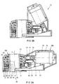
- Fig. 3 shows a side elevation, partly in section, of an embodiment of the movement actuator 10 according to the invention.
- Fig. 4 shows a top plan view, partly in section, of the movement actuator show in Fig. 3.
- the movement actuator 10 as shown comprises a housing 20 and a gear wheel 40 capable of rotating in the housing 20 about the axis 14.
- the gear wheel is coupled, in a manner which will be described in more detail hereinbelow, to a base 41 intended to be mounted on the support 2 of a vehicle, for instance by means of screws or any other means known per se, for which purpose the base 41 may be provided with holes, not shown for simplicity's sake, corresponding to the tapped holes provided in the support 2.
- the housing 20 is intended to be attached to the mirror housing 3, for instance also by means of screws or any other means known per se, for which purpose the housing 20 may also be provided with holes, not shown for simplicity's sake, corresponding to the tapped holes provided in the mirror housing 3.
- the transmission system 60 comprises a worm wheel 61, bearing-mounted in the housing 20 for rotation about a rotation axis 62, and a first worm 63 and a second worm 64 which are attached, concentrically with the rotation axis 62, to the worm wheel 61, on both sides thereof.
- the worm wheel 61 and the two worms 63 and 64 are manufactured as one whole.
- the combination of the worm wheel 61 and the two worms 63 and 64 is bearing-mounted at the ends of the two worms 63 and 64 remote from the worm wheel 61, in the housing 20, with the rotation axis 62 extending substantially horizontally, i.e. substantially perpendicularly relative to the rotation axis 14.
- the first worm 63 is coupled to the gear wheel 40 via a first intermediate gear wheel 65
- the second worm 64 is coupled to the gear wheel 40 via a second intermediate gear wheel 66, which intermediate gear wheels 65, 66 are also bearing-mounted in the housing 20.
- the diameter of the worm wheel 61 is greater than the diameters of the worms 63, 64, and the diameter of the gear wheel 40 is greater than the diameters of the intermediate gear wheels 65, 66. Further, in the embodiment shown, the diameters of the two worms 63, 64 are identical.
- the worm wheel 61 functions as input.
- the worms 63, 64 attached thereto drive the intermediate gear wheels 65, 66 respectively, which, in turn, drive the gear wheel 40, which is thus urged to rotate relative to the housing 20.
- the base 41 coupled to the gear wheel 40 is also urged to rotate relative to the housing 20.
- the transfer of the driving force from the worm wheel 61 to the gear wheel 40 takes place in a parallel manner via two transfer paths, a first transfer path extending via the first worm 63 and the first intermediate gear wheel 65, and a second transfer path extending via the second worm 64 and the second intermediate gear wheel 66. Consequently, these parts are loaded with only half the driving force, while the separate teeth of the gear wheel 40 are also less loaded than in the case where that gear wheel 40 would be driven via a single transfer path. This renders it possible that the driving force to be transferred is greater, and/or that the parts mentioned are manufactured from a less strong material such as synthetic material, and/or that these parts can be relatively small, as a result of which the total size of the actuator 10 can be relatively small.
- the intermediate gear wheels 65, 66 in the example shown are identical, and (as far as their positions are concerned) symmetrically arranged on both sides of the body-symmetrical plane 67 of the worm wheel 61, in which plane the rotation axis 14 extends as well.
- the rotation axes of the intermediate gear wheels 65, 66 are parallel to the rotation axis 14.
- the dimensions of the actuator 10 are relatively slight, due to the particularly compact construction of the transmission system 60.
- various variations are conceivable, each having a particular impact on the degree of compactness that is obtained.
- the angle that is included by the plane 67 and a plane defined by the rotation axis 14 and the rotation axis of the intermediate gear wheel 65 will be designated by the letter ⁇ .
- the width of the actuator 10 can be decreased by reducing the diameter of the gear wheel 40. However, when this is accompanied by a reduction of the number of teeth of the gear wheel 40, this results in a reduced gear ratio. Because the width of the actuator 10 is also determined by the intermediate gear wheels 65, 66, the angle ⁇ and/or the diameter of the intermediate gear wheels 65, 66 would have to be reduced as well. The reduction of the angle ⁇ has as a result that the thickness of the worm wheel 61 should be chosen to be smaller, which implies a weakening of the worm wheel 61.
- the reduction of the diameter of the intermediate gear wheels 65, 66 implies that the center-to-center distance from the worm wheel 61 to the gear wheel 40 can be reduced and the diameter of the worm wheel 61 can be reduced, which results in a decreased length of the actuator 10.
- a decreased diameter of the worm wheel 61 results in a reduction of the number of teeth of the gear wheel 61, which again implies a reduced gear ratio.
- the worms 63 and 64 are in line, it is possible in an embodiment to manufacture the combination of the worms 63 and 64 and the worm wheel 61 by fastening a through worm centrally in the worm wheel 61, for instance through welding or glueing, the parts of that through worm which project on both sides from the worm wheel 61 forming the worms 63 and 64.
- the pitch of the worms 63, 64 is only needed where they are in mesh with the intermediate gear wheels 65 and 66, so that it is also possible to start from a bar in which a worm pitch is cut at two locations in lieu of a through worm, as a result of which the bar has no worm pitch at the location of the worm wheel 61, as shown in Fig. 4. Accordingly, it is also possible to provide the worm pitch only after the bar has been attached to the worm wheel. As a variant, it is possible to start from a worm wheel of relatively great thickness and to turn it down to bar thickness, and to subsequently cut the worm pitch so that the combination of the worms 63 and 64 and the worm wheel 61 are manufactured in one piece. It is also possible to manufacture that combination as a single injection-molded piece or cast piece, or to start from the worms 63, 64 and injection-mold a plastic worm wheel 61 around them.
- the worm wheel 61 is driven by a worm 71 which may be mounted directly on the driven shaft 72 of an electromotor 73.
- the orientation of the electromotor 73 with the worm 71 can further be varied.
- Fig. 3 shows two of the possible variants.
- the shaft 72 of the motor 73 is directed at least substantially perpendicularly to the rotation axis 14, with the worm 71 located above the worm wheel 61.
- the movement actuator has a very slight vertical dimension.
- the shaft 72 of the motor 73 makes a fairly acute angle with the rotation axis 14, with the worm 71 located on the side of the worm wheel 61 facing away from the axis 14. This acute angle is chosen such that the motor 73 does not project beyond the worm 71 in horizontal direction.
- the movement actuator has a very slight horizontal dimension.
- the shaft 72 of the motor 73 is always in the above-mentioned body-symmetrical plane 67 of the worm wheel 61, i.e., a plane perpendicular to the rotation axis 62 of the worm wheel 61.
- the teeth of the worm wheel 61 are commonly inclined relative to that body-symmetrical plane 67 and are at an angle adapted to the pitch of the worm 71.
- the motor 73 is placed obliquely relative to this body-symmetrical plane 67 of the worm wheel 61, i.e.
- the shaft 72 of the motor 73 makes an angle with that body-symmetrical plane 67, which angle is preferably adapted to the pitch of the worm 71 such that the teeth of the worm wheel 61 can be perpendicular to that body-symmetrical plane 67.
- the worm wheel 61 can be manufactured more simply and hence more cheaply without requiring the other parts to be adapted, which advantage is particularly apparent when the worm wheel 61 is manufactured through injection molding.
- the movement actuator shown in Fig. 3 is of modular construction.
- a first module 100 comprises the combination of the housing 20, the base 41 and the transmission chain 60
- a second module 200 comprises the motor 73 with the worm 71 mounted on the driven shaft 72 thereof, and a motor housing 74, wherein the motor 73 is mounted and which can be attached to the housing 20.
- the shapes of the housing 20 and the motor housing 74 are matched to fit together in two manners, as illustrated in Fig. 3.
- the housing 20 and the motor housing 74 can be attached to each other in a manner known per se by means of for instance screwing or glueing, but preferably, this attachment is carried out by means of snap elements.
- This manufacturer can promptly react to a possible demand for one of the two variants by stocking the finished modules, which are formed into a finished actuator merely by attaching the modules to each other.
- stops can be present for defining the rearwardly folded position and the forwardly folded position.
- the movement actuator can be provided with switches 77, as is known per se, arranged inside the housing 20.
- this friction coupling 80 belonging to the first module 100, comprises an annular plate 81, formed on the gear wheel 40 and fitting with a certain interspace around a cylinder 44 that extends upward from the base 41.
- This cylinder 44 preferably manufactured in one piece with the base 41, is hollow in order that conductors (not shown) for exciting the motor can be arranged through it. Extending along the outer wall of the cylinder 44 are axial fingers that are positionally fixed relative to the cylinder 44 and have the function of cams.
- annular plate 81 Disposed above and under that annular plate 81 are a first annular friction plate 82 and a second annular friction plate 83 respectively, which friction plates, at their inside circumferences, are provided with keyways 42 that are in mesh with the fingers 43.
- a third friction plate 84 is located, clear of the fingers 43 but coupled in rotational sense to the gear wheel 40 via coupling elements.
- These coupling elements can be any suitable coupling elements.
- these coupling elements can be formed by a system of mutually enmeshing, radially directed projections and recesses on the third friction plate 84 and the gear wheel 40 respectively, as shown in Fig. 3 at 85.
- the third friction plate 84 rests against an annular supporting wall 21 of the housing 20.
- This supporting wall 21 in turn rests against the base 41, with the interposition of a cam disc 90, coupled in rotational sense to the base 41 via coupling elements.
- These coupling elments can be mutual projections and recesses, as will be understood by anyone skilled in the art.
- This cam disc 90 fuctions as a fourth friction plate between the housing 20 and the base 41.
- the base 41, the fingers 43 and the cam disc 90 can be formed as one whole.
- the fingers 43 and the cam disc 90 are formed as a separate whole, loose from the base 41.
- manufacturing fingers 43 that extend upward from the cam disc 90 in one piece with that cam disc 90 is simpler and cheaper than forming the cams 43 on the cylinder 44.
- the friction plates 82, 81, 83 and 84 are pressed together and against the supporting wall 21 by an end portion of a compression spring 86, which, at its other end portion, bears against a diaphragm spring or check spring 87, which in turn engages the cylinder 44.
- the compression spring 86 is constructed as a helical spring and is arranged so as to be coaxial to the cylinder 44.
- the effect thus achieved is that in spite of the reduced outside dimension of the actuator 10, the pass-through space of the cylinder 44 is enlarged, allowing more conductors to be passed through it, as is for instance desired for exciting a heating element for the mirror.
- the housing 20 and the base 41 are held together as well, with the supporting wall 21 of the housing 20 being pressed against the cam disc 90 functioning as fourth friction plate.
- This compression force is determined, when the compression spring 86 and the diaphragm spring 87 are mounted, by the distance through which the diaphragm spring 87 is slid along the cylinder 44 while compressing the compression spring 86.
- a certain mounting force is exerted on the diaphragm spring 87, downwardly directed parallel to the axis 14 in Fig. 3.
- the compression force exerted by the compression spring 86 is equal to the mounting force.
- the diaphragm spring 87 grips firmly around the cylinder 44, causing the compression spring 86 to keep exerting its thus set compression force on the friction coupling 80.
- the equilibrium of forces follows a closed path formed by the cylinder 44, the diaphragm spring 87, the compression spring 86, the friction plates 82, 81, 83, 84, the supporting wall 21, the cam disc 90, and the base 41, the base 41 forming a functional whole with the cylinder 44.
- An important purpose of the friction coupling 80 is to prevent the transmission system 60 from being damaged when an external force is applied to the mirror housing 3, for instance due to a pedestrian walking against it, but also to enable manual pivoting.
- the operation of the friction coupling 80 is as follows.
- the housing 20 At rest, such as in the operational position, the housing 20 is coupled to the base 41 via the cam disc 90. It is thus provided that external forces, such as wind load, applied to a mirror housing 3 are directly passed to the support 2 without loading the transmission system 60. It is also provided that play, if any, in the transmission system 60 does not influence the stability of the mirror housing 3, because this direct coupling effects that the housing 20 and accordingly the mirror housing 3 are connected free from vibration to the base 41 and accordingly the support 2 of the vehicle 1.
- a suitable maximum friction value for the fourth friction plate (cam disc 90) is 2 Nm.
- the housing 20 is connected with the base 41 via the friction plates 81-84, the fingers 43 and the cam disc 90.
- the motor is excited, as a result of which the gear wheel 40 is urged to rotate relative to the housing 20, as is described more elaborately hereinabove.
- This is of course equivalent to a forced rotation of the housing 20, and accordingly the mirror housing 3, relative to the gear wheel 40, which is now held in a fixed position by the friction plates 81-84 relative to the fingers 43 of the base 41, and accordingly to the support 2 of the vehicle 1. Because the housing 20 and the base 41 rotate relative to one another, the maximum friction value of the fourth friction plate 90 must now be overcome.
- the mirror housing 3 in the operational position, the mirror housing 3 is mounted relative to the vehicle so as to be largely free from vibration, and that pivoting the mirror housing 3 from the operational position by hand requires relatively much force, whereas pivoting the mirror housing 3 electrically requires relatively little force.
- the actuator 10 need not overcome the entire "retaining force", as a result of which the parts of the actuator 10, in particular the parts of the transmission system 60, can be relatively small and can be manufactured from synthetic material, which implies a cost price reduction and enables a more noiseless operation.
- Fig. 5 showing a section, comparable with Fig. 3A, of another embodiment of the actuator, wherein like or comparable parts as in Fig. 3 have been designated by like reference numerals. Further, reference is made to Fig. 6, showing a bottom view of the actuator shown in Fig. 5.
- fastening holes for the base 41 are indicated by the reference numeral 45.
- a cam-shaped protuberance is indicated, formed on the base 41.
- the cam disc 90 has a comparable protuberance 96 which fits around the protuberance 46 of the base 41, providing a securing against rotation of the cam disc 90 relative to the base 41.
- this securing against rotation can also be realized in another manner.
- the protuberance 96 of the cam disc 90 is intended to cooperate with a springy element, in the example shown a first end 111 of a leaf spring 110 whose other end 112 is retained in the housing 20.
- the first end 111 of the leaf spring 110 rests against the cam disc 90, and the press-on force with which that first end 111 presses against the cam disc 90 can be slight.
- the combination of the cam 96 and the springy element 110 serves to define the operational position of the actuator.
- the cam 96 In the rearwardly folded position of the actuator, the cam 96 is clear of the first leaf spring end 111.
- the actuator is moved, manually or electrically, from the rearwardly folded position to the operational position, i.e. the housing 20 rotates anti-clockwise relative to the base 41 in Fig. 6, the first leaf spring end 111 moves along the cam shaft 90, with little or no friction being developed.
- the outer circumference of the cam disc 90 at least at the location of the first leaf spring end 111, has the shape of a circular arc.
- the rotation position wherein the cam 96 and the first leaf spring end 111 touch each other which position is shown in Fig. 6, is the operational position. Because the cam 96 and the first leaf spring end 111 resist a further rotation in the direction mentioned, the user, upon adjusting by hand, will experience the same sensation as if the first leaf spring end 111 were a stop for the cam 96, and he will realize that he has reached the operational position. Likewise, in the case of electrical adjustment, the motor 73 cannot rotate the housing 20 and the base 41 any further relative to each other.
- the motor 73 should now overcome the maximum friction value of the friction plates 81-84.
- a switch 77 included in the feed circuit for the motor 73 can be operated - in a known manner, for that matter - to interrupt the current supply to the motor 73, as a result of which the motor 73 stops. It is observed that this switch 77 does not interrupt the current supply which causes the motor 73 to rotate in the opposite direction, so that it is still possible to pivot electrically from the operational position to the rearwardly folded position.
- a threshold force should be exerted sufficient to cause the cam 96 to press the first leaf spring end 111 outward, with the cam 96 sliding along that first end 111.
- the first leaf spring end 111 is properly rounded and/or bent outward, as shown in Fig. 6, so as to limit the occurrence of wear as much as possible.
- this threshold force depends on, inter alia, the spring constant of the leaf spring 110, the distance between the first leaf spring end 111 and the second leaf spring end 112, the height of the cam 96, and the angle made by the tangent plane between cam 96 and end 111 with the plane through the rotation axis 14 passing through the tangent point, as will be clear to anyone skilled in the art.
- the outer circumference of the cam 96 at least at the location of the first leaf spring end 111, has the shape of a circular arc.
- a small recess can be provided wherein the outside bend of the outwardly bent portion of the first leaf spring end 111 extends, to provide in the operational position some mechanical securing against folding in.
- the base 41 and the cam disc 90 can be considered a unit, and the definition of the operational position in the above-described manner can indeed already be obtained through the base 41 with the cam 46 formed thereon, which is equivalent to a combination, manufactured in one piece, of base and cam disc.
- the presence of the separate cam disc 90 offers the advantage that in that case, the base 41 and the outer surface of the cam 96, which outer surface contacts the first leaf spring end 111, can be made of different materials.
- a metal for instance aluminum
- a synthetic material, for instance PBTP can be chosen in view of the minimization of the occurrent friction and wear.
- a third leaf spring end 113 is present, symmetrical to the above-mentioned first leaf spring end 111.
- a second leaf spring can be used, but preferably, and as for instance shown in more detail in Fig. 7, the actuator comprises a U-shaped pinch spring 110, the first and third leaf spring ends being formed by the ends of the legs of the U, and the common second end 112 being formed by the central bend of the U.
- the U-shaped pinch spring 110 is designed to have its legs exert a pinch force on the base 41 and the cam 96.
- Such a U-shaped pinch spring 110 is in itself force-closed, so that the clamping point of the U-bend 112 need not take up any spring force in that direction. Accordingly, for positioning the U-shaped pinch spring 110, it is sufficient when the housing 20 comprises a support 27 against which the central bend 112 of the U-shaped pinch spring 110 abuts.
- Fig. 7 further shows that in rotation positions between the operational position and the rearwardly folded position the leaf spring ends 111 and 113 can be clear of the cam disc 90.
- the housing 20 of the embodiment shown comprises two further supports 28, arranged next to the legs of the U.
- the spring 110 is arranged with a fairly great pre-tension ("pinching"), which pinching pre-tension is taken up by these supports 28 in the structural variant shown in Fig. 7.
- pinching a fairly great pre-tension
- the friction coupling 80 will not be capable of supplying this force, as a result of which the rotating movement of the cam 96 relative to the first leaf spring end 111 stops at the first contact between cam 96 and end 111, regardless of the precise friction value of the friction coupling 80, which ensures a particularly accurate setting of the operational position.
- a further advantage of the construction shown concerns the fact that the actuator can have a symmetrical operation, permitting the same actuator to be used for a left mirror as well as for a right mirror.
- the operational position is defined by the cooperation of the cam 96 with the first leaf spring end 111, while when used in a right mirror, the operational position is defined by the cooperation of the cam 96 with the third leaf spring end 113. This yields a further cost saving, because it is sufficient for a manufacturer to produce only one type.
- the actuator in a preferred embodiment, has a control element 310 for the motor 73, and a detector 320 for current and/or voltage, as illustrated in Fig. 8.
- This Figure further shows a voltage source 301, in general a battery, and a switch 340 to be operated by the user. Make-and-break contacts 351, 352 of the switch 340 are connected with a first input 311 and a second input 312 respectively of the control element 310.
- the make-and-break contact 351 is connected with the supply voltage and the make-and-break contact 351 is connected with mass.
- this position of the switch 340 corresponds to the operational position of the operating actuator.
- the make-and-break contact 351 is connected with mass and the make-and-break contact 352 is connected with the supply voltage.
- the operating actuator is in the rearwardly folded position, and that the switch 340 is switched in this one position by the user.
- the control element 310 will then connect the first input 311 with a first outpout 313, and connects the second input 312 with a second output 314.
- the current through the motor 73 flows from the conductor 303 to the conductor 304, and the rotation of the motor 73, caused thereby, takes place in a direction corresponding to a pivotal movement from the rearwardly folded position to the operational position.
- a load detector 320 includes a load detector 320.
- this load detector 320 consists of a current detector.
- An output 321 of the load detector 320 is connected with a detection input 315 of the control element 310.
- the control element 310 is adapted to monitor to signals supplied by the load detector 320, and to interrupt the connection of the first input 311 with the first output 313 and/or the connection of the second input 312 with the second output 314 and thus switch off the motor 73 when the received signals are indicative of the load increase.
- a signal indicative of the load increase is formed by the increase of the current intensity measured.
- the load increase is caused by an opposition that is experienced when the actuator is pivoted further. This opposition is for instance caused when the rearwardly folded position defined by the stops is reached, or when the cam 96 presses against an end 111, 113 of the leaf spring 110.
- the control device 310 When the user switches the switch 340 into another position, the control device 310 detects a voltage reversal at its inputs 311, 312. In response thereto, the control device 310 re-establishes the above-mentioned connection between the inputs 311, 312 and the above-mentioned outputs 313, 314, causing the motor 73 to rotate in an opposite direction so as to bring the movement actuator into the rearwardly folded position.
- This embodiment offers the additional advantage that the motor 73 is also stopped when the pivotal movement is blocked by any other cause, which hence means an extra security against the occurrence of damage.
- control device can be adapted to compare the received signals with priorly inputted threshold values, and to interrupt the above-mentioned connections when one or several of the received siqnals exceeds or falls below the associated threshold value. In this respect, it may be advantageous if there is a slight time delay between the time of detection and the time of switching off.
- a temperature detector (not shown) is present, disposed in the proximity of the motor 73 to detect heating up of the motor and to provide to the control device 310 a signal indicative of the temperature of the motor 73, permitting the control device 310 to switch off the motor 73 also if it should become overheated by whatever cause.
- the load detector 320 detects electric signals, it need not be mounted in the direct proximity of the pivoting mechanism. In a particular embodiment, the load detector 320 and the control device 310 can even be accommodated in the interior of the associated vehicle. It is thus provided that the actuator itself need not have any elements relating to the switching-off operation of the motor 73, and can hence have the slightest possible dimensions.
- control device 310 with associated load detector 320 for each separate motor offers practical advantages, because it will then be easier to adapt the control device 310 with associated load detector 320 to the specific characteristic of a particular motor. Further, it will then be easier to have the control device 310 react to temperature changes of that motor.
- the load detector 320 is not a separate component, but is a part of the control device 310, which can for instance be constructed as an integrated circuit.
- the above-mentioned temperature detector can be part of that integrated circuit as well.
- the load detector 320 is not a separate component, but is a part of the control device 310, which can for instance be constructed as an integrated circuit.
- the above-mentioned temperature detector can be part of that integrated circuit as well.
Landscapes
- Engineering & Computer Science (AREA)
- Mechanical Engineering (AREA)
- General Engineering & Computer Science (AREA)
- Multimedia (AREA)
- Rear-View Mirror Devices That Are Mounted On The Exterior Of The Vehicle (AREA)
- Vehicle Body Suspensions (AREA)
- Transmission Devices (AREA)
- Gear Transmission (AREA)
- Reciprocating, Oscillating Or Vibrating Motors (AREA)
- Fuel-Injection Apparatus (AREA)
- Valve Device For Special Equipments (AREA)
- Connection Of Motors, Electrical Generators, Mechanical Devices, And The Like (AREA)
- Fluid-Damping Devices (AREA)
- Body Structure For Vehicles (AREA)
- Superstructure Of Vehicle (AREA)
- Actuator (AREA)
- Lock And Its Accessories (AREA)
- Electromechanical Clocks (AREA)
Abstract
Description
- gear wheel 40:
- tip diameter ≈ 31.53 mm number of teeth = 50
- gear wheel 65:
- tip diameter ≈ 11.04 mm number of teeth = 16 angle α ≈ 23.10°
- gear wheel 66:
- identical to
gear wheel 65 - worm wheel 61:
- tip diameter ≈ 18.61 mm number of teeth = 35
- worm 63:
- tip diameter ≈ 5.04 mm pitch (single) ≈ 9°
- worm 64:
- identical to
worm 63 torsion angle β: 0°
Claims (27)
- A movement actuator (10) comprising a first actuator part (11;41) and a second actuator part (12;20) that are rotatably mounted relative to one another, an electromotor (73) for rotating the two actuator parts (11,12;41,20) relative to one another, a transmission system (60) coupled between the electromotor (73) and said actuator parts (11,12; 41,20), said transmission system (60) comprising a first gear wheel (61) and two worms (63,64) with identical diameters over their length concentrically attached to said first gear wheel (61), a second gear wheel (40) rotatably arranged in the second actuator part (20) and coupled to the two worms (63,64) with the interposition of respective intermediate gear wheels (65,66), the diameter of the second gear wheel (40) being greater than the diameters of the intermediate gear wheels (65,66), characterized in that the worms are of unitary construction and arranged on both sides of the first gear wheel (61), the first gear wheel (61) being a worm wheel with a diameter greater than the diameter of the worms (63,64), and each worm (63,64) meshing with a respective intermediate gear wheel (65,66) with each intermediate gear wheel in turn meshing with said second gear wheel (40).
- A movement actuator according to claim 1,
characterized in that the worm wheel (61) and the two worms (63,64) are of unitary construction. - A movement actuator according to claim 1 or 2,
characterized in that the two worms (63, 64) are twisted relative to one another around the longitudinal axis. - A movement actuator according to any one of claims 1-3, characterized in that the two intermediate gear wheels (65,66) are identical and symmetrically arranged on both sides of the body-symmetrical plane (67) of the worm wheel (61).
- A movement actuator according to any one of the claims 1-4, characterized in that switches (77) are provided, operable by the second gear wheel (40), for switching off the motor (73), said switches being arranged on both sides of the worm wheel (61), above the worms (63, 64) and the intermediate gear wheels (65, 66) within the second actuator part (20).
- A movement actuator according to any one of claims 1-5, characterized in that the actuator (10) is of modular design, a first module (100) comprising the combination of the second actuator part (20), the first actuator part (41) and the transmission chain (60), and a second module (200) comprising the combination of a motor housing (74) having the motor (73) mounted therein and a worm (71) mounted on the driven shaft (72) thereof, the shape of the first and second module being matched to fit together in two manners.
- A movement actuator according to any one of the claims 1-6, characterized in that the second gear wheel (40) is coupled to the first actuator part (41) via a friction coupling (80).
- A movement actuator according to claim 7, characterized in that the friction coupling (80) comprises at least an annular plate (81) associated with the second gear wheel (40) and at least an annular friction plate (82, 83) associated with the first actuator part (41).
- A movement actuator according to claim 7 or 8, characterized in that a part (84) of the friction coupling (80) that is associated with the second gear wheel (40) rests again an annular supporting wall (21) of the second actuator part (20), and that the friction coupling (80) is pressed down by a compression spring (86) whose other end engages the first actuator part (41).
- A movement actuator according to claim 9, characterized in that the other end of the compression spring (86) engages, via a check spring (87), a hollow cylinder (44) extending from the first actuator part (41).
- A movement actuator according to claim 10, characterized in that the compression spring (86) is designed as a helical spring coaxially disposed around the cylinder (44).
- A movement actuator according to any one of claims 9-11, characterized in that the supporting wall (21) presses against the first actuator part (41) under the influence of the compression spring (86).
- A movement according to any one of the claims 9-12, characterized in that a cam disc (90) is arranged between the supporting wall (21) and the first actuator part (41), which cam disc (90) is secured against rotation relative to the first actuator part (41).
- A movement actuator according to claim 13, characterized in that a cam-shaped protuberance (46) respectively (96) is formed on the first actuator part (41) and/or the cam disc (90).
- A movement actuator according to claim 14, characterized in that a springy element (110) is associated with the second actuator part (20) for cooperation with the cam (46, 96) to define an operational position.
- A movement actuator according to claim 15, characterized in that at least at the location of the springy element (110), the outer circumference of the cam (46,96) has the shape of a circular arc.
- A movement actuator according to claim 15 or 16, characterized in that the springy element (110) is a leaf spring, a first end (111) of which cooperates with the cam (46, 96) and a second end (112) of which is retained in the second actuator part (20).
- A movement actuator according to claim 17, characterized in that a third leaf spring end (113) is arranged so as to be symmetrical to the first leaf spring end (111), also for cooperation with the cam (46, 96) to define an operational position.
- A movement actuator according to claim 18, characterized in that the springy element (110) is a U-shaped spring, the first and third leaf spring ends (111, 113) being formed by the ends of the legs of the U that are only loaded for bending outwards, and the common second end (112) being formed by the central bend of the U.
- A movement actuator according to any one of the preceding claims, characterized in that it comprises a control element (310) for the motor (73), and a load detector (320) coupled to an input (315) of the control element (310) and included in a supply line of the motor (73).
- A movement actuator according to claim 20, characterized in that the load detector (320) comprises a current detector and/or voltage detector.
- A movement actuator according to claim 20 or 21, characterized in that it further comprises a temperature detector coupled to the control device (310) and disposed in the proximity of the motor (73).
- A movement actuator according to any one of claims 20-22, characterized in that the control device (310) is adapted to interrupt, in response to the detection of a load increase, a connection from a supply source (301) to the motor (73) and to remove said interruption not until the control device (310) detects a polarity reversal at an input (311, 312).
- A module (100) for a movement actuator according to any one of the preceding claims, comprising the combination of the second actuator part (20), the first actuator part (41) and the transmission chain (60).
- A module (200) for a movement actuator according to any one of claims 1-23, comprising the combination of a motor housing (74) having the motor (73) mounted therein and a worm (71) mounted on the driven shaft (72) thereof.
- A wing mirror system for a vehicle, comprising a rear view mirror (5) provided in a mirror housing (3) and a movement actuator (10) arranged in the mirror housing (3) according to any one of claims 1-23.
- A wing mirror system according to claim 26, characterized in that the load detector (320) and the control device (310) are arranged in the mirror housing (3).
Applications Claiming Priority (3)
| Application Number | Priority Date | Filing Date | Title |
|---|---|---|---|
| NL9400163A NL9400163A (en) | 1994-02-02 | 1994-02-02 | Movement actuator. |
| NL9400163 | 1994-02-02 | ||
| PCT/NL1995/000049 WO1995021339A1 (en) | 1994-02-02 | 1995-02-02 | Movement actuator |
Publications (2)
| Publication Number | Publication Date |
|---|---|
| EP0741843A1 EP0741843A1 (en) | 1996-11-13 |
| EP0741843B1 true EP0741843B1 (en) | 1998-11-11 |
Family
ID=19863779
Family Applications (1)
| Application Number | Title | Priority Date | Filing Date |
|---|---|---|---|
| EP95907140A Expired - Lifetime EP0741843B1 (en) | 1994-02-02 | 1995-02-02 | Movement actuator |
Country Status (13)
| Country | Link |
|---|---|
| US (1) | US5823054A (en) |
| EP (1) | EP0741843B1 (en) |
| JP (1) | JP2869430B2 (en) |
| KR (1) | KR100363629B1 (en) |
| AT (1) | ATE173326T1 (en) |
| AU (1) | AU689204B2 (en) |
| BR (1) | BR9506706A (en) |
| CA (1) | CA2182599A1 (en) |
| DE (1) | DE69505948T2 (en) |
| ES (1) | ES2125592T3 (en) |
| MX (1) | MX9603169A (en) |
| NL (1) | NL9400163A (en) |
| WO (1) | WO1995021339A1 (en) |
Families Citing this family (28)
| Publication number | Priority date | Publication date | Assignee | Title |
|---|---|---|---|---|
| NL1003144C2 (en) * | 1996-05-15 | 1997-11-18 | Iku Holding Montfoort Bv | Electrically operated hinge actuator, and outside mirror with electrically operated hinge mechanism. |
| JP3851423B2 (en) * | 1997-08-28 | 2006-11-29 | 株式会社ミツバ | Wiper control method |
| AU775700B2 (en) * | 1999-04-09 | 2004-08-12 | Magna Mirror Systems Inc. | An extendable and pivotal rearview mirror assembly |
| DE20013357U1 (en) * | 2000-08-03 | 2000-09-28 | Reitter & Schefenacker GmbH & Co. KG, 73730 Esslingen | Exterior rear view mirror for vehicles, in particular for motor vehicles |
| US7216996B2 (en) * | 2001-06-15 | 2007-05-15 | Schefenacker Vision Systems Uk Ltd. | Mirror with interchangeable appearance covers |
| JP2003312364A (en) * | 2002-04-19 | 2003-11-06 | Murakami Corp | Angle control device for vehicle mirror |
| US7070287B2 (en) * | 2002-04-23 | 2006-07-04 | Magna Donnelly Mirrors North America L.L.C. | Vehicular mirror system with at least one of power-fold and power-extend functionality |
| JP2003346515A (en) * | 2002-05-30 | 2003-12-05 | Koito Mfg Co Ltd | Vehicle headlight leveling device |
| CN1681629A (en) * | 2002-09-06 | 2005-10-12 | 貝特彻工业公司 | Low-cost ring blade for rotary knives |
| US7303297B1 (en) | 2003-02-27 | 2007-12-04 | Magna Donnelly Mirrors North America L.L.C. | Vehicular mirror with improved bearing fit |
| WO2005075249A1 (en) * | 2004-02-06 | 2005-08-18 | Eaton Automotive B.V. | Hinge actuator and method for adjusting two parts of a hinge actuator relative to each other |
| DE102006021249B3 (en) * | 2006-05-04 | 2007-10-25 | Bühler Motor GmbH | Wing mirror with retracting drive has the main gear as a one piece plastic molding with the ratchet stops |
| US7966904B2 (en) | 2006-05-05 | 2011-06-28 | Questek Manufacturing Corporation | Low axial play drive system |
| KR100963386B1 (en) | 2008-12-18 | 2010-06-14 | 에스엠알 페턴츠 에스.에이.알.엘. | Driver for outside view mirror for vehicle |
| DE102009010458B4 (en) * | 2009-02-13 | 2019-08-29 | Automotive Lighting Reutlingen Gmbh | Adjustable motor vehicle headlight with a low-backlash gear |
| US11498486B2 (en) | 2009-10-07 | 2022-11-15 | Magna Mirrors Of America, Inc. | Vehicular exterior rearview mirror assembly |
| US10261648B2 (en) | 2009-10-07 | 2019-04-16 | Magna Mirrors Of America, Inc. | Exterior rearview mirror assembly |
| US9969334B2 (en) | 2010-02-10 | 2018-05-15 | Magna Mirrors Of America, Inc. | Exterior rearview mirror assembly |
| US12115913B2 (en) | 2010-02-10 | 2024-10-15 | Magna Mirrors Of America, Inc. | Vehicular exterior rearview mirror system |
| US9827913B2 (en) | 2010-02-10 | 2017-11-28 | Magna Mirrors Of America, Inc. | Exterior rearview mirror assembly |
| US9067541B2 (en) | 2011-10-31 | 2015-06-30 | Magna Mirrors Of America, Inc. | Exterior mirror assembly with actuator |
| US8876079B2 (en) * | 2012-05-30 | 2014-11-04 | Ncr Corporation | Display location |
| GB2512071A (en) | 2013-03-19 | 2014-09-24 | Johnson Electric Sa | Grille shutter actuator |
| US9676336B2 (en) | 2013-06-25 | 2017-06-13 | Magna Mirrors Of America, Inc. | Exterior rearview mirror assembly for vehicle |
| US9487142B2 (en) | 2013-06-25 | 2016-11-08 | Magna Mirrors Of America, Inc. | Rearview mirror assembly for vehicle |
| US11078997B2 (en) * | 2015-07-20 | 2021-08-03 | National Machine Group | Motor driven electromechanical actuator |
| US20170158136A1 (en) * | 2015-12-02 | 2017-06-08 | Ford Global Technologies, Llc | Vehicle side mirror system |
| CN215621772U (en) * | 2020-10-20 | 2022-01-25 | Sl镜子科技株式会社 | Camera mirror assembly for vehicle |
Family Cites Families (13)
| Publication number | Priority date | Publication date | Assignee | Title |
|---|---|---|---|---|
| US1405359A (en) * | 1921-08-02 | 1922-01-31 | Paul V Troupe | Differential transmission gearing |
| US1594987A (en) * | 1925-02-19 | 1926-08-03 | Thomas E Adams | Internal worm gear |
| US1751650A (en) * | 1927-06-01 | 1930-03-25 | Henry W Nieman | Power-transmission mechanism |
| DE855929C (en) * | 1939-01-05 | 1952-11-17 | Mitteldeutsche Stahlwerke G M | Gearboxes with two or more drive wheels, especially for excavators and cranes |
| DE2522621A1 (en) * | 1975-05-22 | 1976-11-25 | Walcher Elektromaschinenbau Kg | Temp. monitor and warning circuit for electric motors - has photo-detector probe near rotor and externally-mounted element |
| EP0100810A3 (en) * | 1982-07-15 | 1985-01-23 | IGM - Industriegeräte- und Maschinenfabriks-gesellschaft mbH | Speed reducer |
| JPS63173745A (en) * | 1987-01-13 | 1988-07-18 | Murakami Kaimeidou:Kk | Electric flexible door mirror |
| JPH0249638U (en) * | 1988-09-30 | 1990-04-06 | ||
| US5080492A (en) * | 1988-12-09 | 1992-01-14 | Platzer Jr George E | Mirror and apparatus for positioning mirror |
| NL8902300A (en) * | 1989-09-14 | 1991-04-02 | Iku Holding Montfoort Bv | FLIP-UP MECHANISM FOR A REAR VIEW MIRROR FOR A VEHICLE. |
| JPH04136949U (en) * | 1991-06-17 | 1992-12-21 | 株式会社村上開明堂 | foldable door mirror |
| JP2604693Y2 (en) * | 1992-09-16 | 2000-05-22 | 株式会社村上開明堂 | Electric retractable door mirror |
| US5467230A (en) * | 1993-08-16 | 1995-11-14 | Lowell Engineering Corp. | Dual pivoted member mount for mirror |
-
1994
- 1994-02-02 NL NL9400163A patent/NL9400163A/en not_active Application Discontinuation
-
1995
- 1995-02-02 WO PCT/NL1995/000049 patent/WO1995021339A1/en not_active Ceased
- 1995-02-02 AT AT95907140T patent/ATE173326T1/en not_active IP Right Cessation
- 1995-02-02 US US08/687,375 patent/US5823054A/en not_active Expired - Fee Related
- 1995-02-02 MX MX9603169A patent/MX9603169A/en not_active IP Right Cessation
- 1995-02-02 DE DE69505948T patent/DE69505948T2/en not_active Expired - Fee Related
- 1995-02-02 CA CA002182599A patent/CA2182599A1/en not_active Abandoned
- 1995-02-02 AU AU15456/95A patent/AU689204B2/en not_active Ceased
- 1995-02-02 KR KR1019960704196A patent/KR100363629B1/en not_active Expired - Fee Related
- 1995-02-02 BR BR9506706A patent/BR9506706A/en not_active IP Right Cessation
- 1995-02-02 JP JP7520518A patent/JP2869430B2/en not_active Expired - Fee Related
- 1995-02-02 EP EP95907140A patent/EP0741843B1/en not_active Expired - Lifetime
- 1995-02-02 ES ES95907140T patent/ES2125592T3/en not_active Expired - Lifetime
Also Published As
| Publication number | Publication date |
|---|---|
| KR100363629B1 (en) | 2003-02-05 |
| ATE173326T1 (en) | 1998-11-15 |
| JPH09511379A (en) | 1997-11-11 |
| EP0741843A1 (en) | 1996-11-13 |
| NL9400163A (en) | 1995-09-01 |
| BR9506706A (en) | 1997-09-09 |
| WO1995021339A1 (en) | 1995-08-10 |
| AU689204B2 (en) | 1998-03-26 |
| ES2125592T3 (en) | 1999-03-01 |
| DE69505948T2 (en) | 1999-06-17 |
| MX9603169A (en) | 1997-05-31 |
| US5823054A (en) | 1998-10-20 |
| DE69505948D1 (en) | 1998-12-17 |
| JP2869430B2 (en) | 1999-03-10 |
| AU1545695A (en) | 1995-08-21 |
| CA2182599A1 (en) | 1995-08-10 |
Similar Documents
| Publication | Publication Date | Title |
|---|---|---|
| US5823054A (en) | Movement actuator | |
| KR100425075B1 (en) | Single pivot type electric folding rearview mirror | |
| US6793358B2 (en) | Outer mirror for vehicle | |
| KR100668007B1 (en) | Extendable and pivotable rear view mirror assembly | |
| US5703731A (en) | Exterior mirror with indexing and control pivoting | |
| EP1754630B1 (en) | Lowering mechanism for the exterior rear-view mirrors of motor vehicles | |
| AU710167B2 (en) | Electrically operable pivoting actuator, and wing mirror having an electrically operable pivoting mechanism | |
| US7008067B2 (en) | Electrically operable pivoting actuator for door mirror of motor vehicle | |
| KR19990087570A (en) | External mirror with indexing and control pivot | |
| US6172311B1 (en) | Lever switch | |
| EP0944496B1 (en) | Mirror assembly with friction drive | |
| WO1998026956A9 (en) | Mirror assembly with friction drive | |
| JP2564079Y2 (en) | Rearview mirror angle adjustment mechanism | |
| US4828361A (en) | Semi-automatic rear view mirror assembly | |
| US7318649B2 (en) | Outer rear-view mirror unit for a motor-vehicle with shape memory actuating means | |
| EP1129905B1 (en) | An external rearview mirror | |
| JP2606783Y2 (en) | Power window motor with position switch | |
| CN222845251U (en) | Vehicle-mounted display device and automobile | |
| CN217654466U (en) | Rearview mirror sensor with double-gear structure | |
| KR200397778Y1 (en) | The unit to control glare in outside mirror | |
| KR920005583Y1 (en) | Automotive rearview mirror with auto-expanding range | |
| KR19980037476A (en) | Head restraint device of car | |
| JPH0593989U (en) | Rearview mirror drive mechanism | |
| JP2000318524A (en) | Mirror stay driving device | |
| KR19980055173A (en) | Electric variable room mirror |
Legal Events
| Date | Code | Title | Description |
|---|---|---|---|
| PUAI | Public reference made under article 153(3) epc to a published international application that has entered the european phase |
Free format text: ORIGINAL CODE: 0009012 |
|
| 17P | Request for examination filed |
Effective date: 19960802 |
|
| AK | Designated contracting states |
Kind code of ref document: A1 Designated state(s): AT DE ES FR GB IT NL SE |
|
| 17Q | First examination report despatched |
Effective date: 19970522 |
|
| GRAG | Despatch of communication of intention to grant |
Free format text: ORIGINAL CODE: EPIDOS AGRA |
|
| GRAG | Despatch of communication of intention to grant |
Free format text: ORIGINAL CODE: EPIDOS AGRA |
|
| GRAG | Despatch of communication of intention to grant |
Free format text: ORIGINAL CODE: EPIDOS AGRA |
|
| GRAH | Despatch of communication of intention to grant a patent |
Free format text: ORIGINAL CODE: EPIDOS IGRA |
|
| GRAH | Despatch of communication of intention to grant a patent |
Free format text: ORIGINAL CODE: EPIDOS IGRA |
|
| GRAA | (expected) grant |
Free format text: ORIGINAL CODE: 0009210 |
|
| AK | Designated contracting states |
Kind code of ref document: B1 Designated state(s): AT DE ES FR GB IT NL SE |
|
| REF | Corresponds to: |
Ref document number: 173326 Country of ref document: AT Date of ref document: 19981115 Kind code of ref document: T |
|
| REF | Corresponds to: |
Ref document number: 69505948 Country of ref document: DE Date of ref document: 19981217 |
|
| REG | Reference to a national code |
Ref country code: ES Ref legal event code: FG2A Ref document number: 2125592 Country of ref document: ES Kind code of ref document: T3 |
|
| ET | Fr: translation filed | ||
| PLBE | No opposition filed within time limit |
Free format text: ORIGINAL CODE: 0009261 |
|
| STAA | Information on the status of an ep patent application or granted ep patent |
Free format text: STATUS: NO OPPOSITION FILED WITHIN TIME LIMIT |
|
| 26N | No opposition filed | ||
| REG | Reference to a national code |
Ref country code: GB Ref legal event code: IF02 |
|
| PGFP | Annual fee paid to national office [announced via postgrant information from national office to epo] |
Ref country code: NL Payment date: 20050110 Year of fee payment: 11 Ref country code: AT Payment date: 20050110 Year of fee payment: 11 |
|
| PGFP | Annual fee paid to national office [announced via postgrant information from national office to epo] |
Ref country code: SE Payment date: 20050203 Year of fee payment: 11 |
|
| PGFP | Annual fee paid to national office [announced via postgrant information from national office to epo] |
Ref country code: ES Payment date: 20050211 Year of fee payment: 11 |
|
| PG25 | Lapsed in a contracting state [announced via postgrant information from national office to epo] |
Ref country code: AT Free format text: LAPSE BECAUSE OF NON-PAYMENT OF DUE FEES Effective date: 20060202 |
|
| PG25 | Lapsed in a contracting state [announced via postgrant information from national office to epo] |
Ref country code: SE Free format text: LAPSE BECAUSE OF NON-PAYMENT OF DUE FEES Effective date: 20060203 Ref country code: ES Free format text: LAPSE BECAUSE OF NON-PAYMENT OF DUE FEES Effective date: 20060203 |
|
| PGFP | Annual fee paid to national office [announced via postgrant information from national office to epo] |
Ref country code: IT Payment date: 20060228 Year of fee payment: 12 |
|
| PG25 | Lapsed in a contracting state [announced via postgrant information from national office to epo] |
Ref country code: NL Free format text: LAPSE BECAUSE OF NON-PAYMENT OF DUE FEES Effective date: 20060901 |
|
| EUG | Se: european patent has lapsed | ||
| NLV4 | Nl: lapsed or anulled due to non-payment of the annual fee |
Effective date: 20060901 |
|
| REG | Reference to a national code |
Ref country code: ES Ref legal event code: FD2A Effective date: 20060203 |
|
| PGFP | Annual fee paid to national office [announced via postgrant information from national office to epo] |
Ref country code: GB Payment date: 20080108 Year of fee payment: 14 Ref country code: DE Payment date: 20080229 Year of fee payment: 14 |
|
| PGFP | Annual fee paid to national office [announced via postgrant information from national office to epo] |
Ref country code: FR Payment date: 20080212 Year of fee payment: 14 |
|
| PG25 | Lapsed in a contracting state [announced via postgrant information from national office to epo] |
Ref country code: IT Free format text: LAPSE BECAUSE OF NON-PAYMENT OF DUE FEES Effective date: 20070202 |
|
| GBPC | Gb: european patent ceased through non-payment of renewal fee |
Effective date: 20090202 |
|
| REG | Reference to a national code |
Ref country code: FR Ref legal event code: ST Effective date: 20091030 |
|
| PG25 | Lapsed in a contracting state [announced via postgrant information from national office to epo] |
Ref country code: DE Free format text: LAPSE BECAUSE OF NON-PAYMENT OF DUE FEES Effective date: 20090901 |
|
| PG25 | Lapsed in a contracting state [announced via postgrant information from national office to epo] |
Ref country code: GB Free format text: LAPSE BECAUSE OF NON-PAYMENT OF DUE FEES Effective date: 20090202 Ref country code: FR Free format text: LAPSE BECAUSE OF NON-PAYMENT OF DUE FEES Effective date: 20090302 |