EP0738649B1 - Seitenwand für Fahrzeuge - Google Patents
Seitenwand für Fahrzeuge Download PDFInfo
- Publication number
- EP0738649B1 EP0738649B1 EP96890070A EP96890070A EP0738649B1 EP 0738649 B1 EP0738649 B1 EP 0738649B1 EP 96890070 A EP96890070 A EP 96890070A EP 96890070 A EP96890070 A EP 96890070A EP 0738649 B1 EP0738649 B1 EP 0738649B1
- Authority
- EP
- European Patent Office
- Prior art keywords
- side wall
- pivot pin
- wall portion
- vehicle body
- vehicle
- Prior art date
- Legal status (The legal status is an assumption and is not a legal conclusion. Google has not performed a legal analysis and makes no representation as to the accuracy of the status listed.)
- Expired - Lifetime
Links
- 230000000295 complement effect Effects 0.000 claims description 3
- 238000010276 construction Methods 0.000 description 6
- XEEYBQQBJWHFJM-UHFFFAOYSA-N Iron Chemical compound [Fe] XEEYBQQBJWHFJM-UHFFFAOYSA-N 0.000 description 2
- 230000006378 damage Effects 0.000 description 2
- 238000006073 displacement reaction Methods 0.000 description 2
- 230000000694 effects Effects 0.000 description 2
- 101100498160 Mus musculus Dach1 gene Proteins 0.000 description 1
- 208000027418 Wounds and injury Diseases 0.000 description 1
- 238000004873 anchoring Methods 0.000 description 1
- 238000005452 bending Methods 0.000 description 1
- 239000002131 composite material Substances 0.000 description 1
- 239000013013 elastic material Substances 0.000 description 1
- 208000014674 injury Diseases 0.000 description 1
- 229910052742 iron Inorganic materials 0.000 description 1
- 239000000463 material Substances 0.000 description 1
- 238000000034 method Methods 0.000 description 1
- 238000007789 sealing Methods 0.000 description 1
- 238000004904 shortening Methods 0.000 description 1
- XLYOFNOQVPJJNP-UHFFFAOYSA-N water Substances O XLYOFNOQVPJJNP-UHFFFAOYSA-N 0.000 description 1
Images





Classifications
-
- B—PERFORMING OPERATIONS; TRANSPORTING
- B60—VEHICLES IN GENERAL
- B60J—WINDOWS, WINDSCREENS, NON-FIXED ROOFS, DOORS, OR SIMILAR DEVICES FOR VEHICLES; REMOVABLE EXTERNAL PROTECTIVE COVERINGS SPECIALLY ADAPTED FOR VEHICLES
- B60J5/00—Doors
- B60J5/04—Doors arranged at the vehicle sides
- B60J5/0497—Doors arranged at the vehicle sides for load transporting vehicles or public transport, e.g. lorries, trucks, buses
- B60J5/0498—Doors arranged at the vehicle sides for load transporting vehicles or public transport, e.g. lorries, trucks, buses with rigid panels pivoting about a horizontal axis
Definitions
- the invention relates to a side wall for the construction of a vehicle according to the Preamble of claim 1.
- Horizontally divided side walls in which one side wall part is folded down, also prevent driving with the vehicle with the side wall open, as this either touches the ground or the vehicle or strikes it.
- a side wall of the type mentioned at the outset is described, for example, in BE 719 007 A. described.
- This side wall serves in particular as a cover for the luggage storage compartments of coaches.
- a pivoting of the side wall above the roof of the body of the Vehicle is not possible with this construction.
- the side wall according to the BE 744 868 A where the lower longitudinal edge of the lower wall part on the body of the vehicle leads to a complete opening.
- a box structure for trucks in which the Wall as a folding flap made of at least two individual parts articulated together is formed, wherein the upper wall part is hinged to the structure.
- the lower Wall part carries rollers in the lower edge area, which in guides of the vehicle body intervention.
- the construction of DE 31 02 891 A1 is by a two-part door flap characterized, the lower part of the door flap by a pivot lever upwards is moved.
- the wall is only up to 90 ° or something in these two constructions can be opened over it and can therefore serve as weather protection during loading and unloading.
- the opened wall is an obstacle for a forklift and can Maneuvering of the vehicle is only possible to a limited extent.
- the loading wall of a truck according to DE 29 19 608 A1 is in a lower and divided an upper part of the wall and can with the help of a cable that is at the bottom Edge area of the lower side wall part attacks, be unfolded. Through a hinged roof part allows a complete opening.
- the necessary one Mechanism is very complex and, moreover, cable pulls pose a risk compared to the use of levers or handlebars, because if the rope breaks the loading wall could fall down and endanger people
- the structure in DE 30 46 178 is similar A1 described structure for a truck, the collapsed Side wall parts can be pulled into the hold under the roof of the vehicle. As a result, the side wall parts are not an obstacle for a forklift and let in Maneuver the vehicle, but part of the valuable loading volume goes for the Housing the side wall lost.
- the construction according to FR 2 710 019 A1 also has one in two horizontal parts divided, hinged side wall of a truck body, the upper side wall part can be pivoted by lever and articulated on the upper side wall part attached lower side wall part is freely pivoted.
- the whole Sidewall can be swung up over the roof, the height of the folded side wall on the roof corresponds to the height of the lower wall part.
- the freely pivoting lower wall section poses a risk of injury to people and damage to vehicles or buildings.
- the object of the present invention is to overcome the disadvantages mentioned above avoid and suggest a side wall for vehicles that saves as much space as possible motorized over a large area of the respective vehicle side and with little effort can be opened and closed and at the same time safe driving of the vehicle allowed.
- the arrangement according to the invention divides the entire side wall into two wall parts subdivided, with only a maximum of laterally and / or above the vehicle smaller wall part results in corresponding space requirements. Since no side wall parts with the Contact with the ground is also safe driving with the vehicle open Side wall possible. By the drive-free handlebar or a safe guidance of the guaranteed free end of the lower wall part and a dangerous swinging, hitting od. The like avoided.
- the side wall With partial opening, the side wall essentially provides Lower wall part oriented vertically downward to protect the loading opening and the Vehicle interior against weather influences. It also ensures that the End of the lower wall part no further than the length of the or each handlebar from the vehicle sticking out.
- the third axis is advantageously close to the first axis, preferably arranged offset in the direction of the vehicle center.
- the third axis can also be arranged coaxially to the first axis.
- the end of the or each lifting arm articulated on the upper wall part or an associated guide element, such as a pin or the like in the plane of upper wall part is slidable.
- the wall part could also be adjustable in length by the lifting arm itself be carried out, for example in the form of a telescopic rod of two or more telescoping pipe sections.
- a particularly simple, stable and fail-safe variant to guarantee the Swiveling of the wall part when the axis of rotation and the articulation point do not coincide the lifting arm can also be achieved by the articulated on the upper wall part End of the or each lifting arm or the associated guide element, e.g. of the Pin or the like, provided in the plane of the upper wall part, preferably the Form of a groove, a profile or the like. Guide is guided.
- the axis of rotation is close to the lower one Longitudinal edge of the lower wall part arranged and the other end of the or each handlebar in the middle between the third axis connected to the or each lifting arm and the Axis of rotation articulated on a stand of the vehicle body.
- the lower longitudinal edge is the lower Provide wall part with an approach and on the vehicle body one, this approach in closed end position of the side wall overlapping opposite holder provided. This ensures that shortly before reaching the closed end position Sidewall the free end of the lower wall part comes into a safe guide and the Sidewall can be closed easily. At the same time, this is also one Locking of the lower wall section against unintentional opening guaranteed.
- the first Axis outside of an upper corner area of the Vehicle body is arranged. This allows the sidewall to be completely out of the area the opening of the body of the vehicle intended for loading and unloading and are advantageously pivoted particularly close to the center of the vehicle, so that a the largest possible area for the loading work and the space required for the Vehicle is minimized with the side wall open.
- a hydraulic cylinder-piston unit For driving the lifting arm of the side wall according to the invention with little effort and high functional reliability, this takes place according to an advantageous embodiment by a hydraulic cylinder-piston unit, the movable part, preferably the piston rod of the hydraulic cylinder-piston unit with a flexible element, for example a chain, a rope or a toothed belt, which Element is guided over a curved guide that is rotatably connected to the pivotable Vehicle body articulated end of the lifting arm is connected.
- a flexible element for example a chain, a rope or a toothed belt
- Another object of the present invention is therefore to ensure safe closing the side wall without additional aids and avoiding the above Allow disadvantages.
- the or each link in his Length is changeable.
- the lower longitudinal edge of the lower wall part the vertical part of the vehicle body at an angle and moved then extending the handlebar along the vertical part of the vehicle body until there is a complete closure of the side wall and also the wall part is arranged vertically parallel to the vertical part of the vehicle body.
- the handlebar performs a pure rotary movement.
- the after touching the lower wall part with the vehicle body in an almost exclusive longitudinal movement passes. This ensures safe guidance of the side wall the vehicle in a corresponding guide or similar. guaranteed on the vehicle body. It are no additional sealing means such as Hook or bolt necessary and the Vehicle drivers do not have to open any hooks or bolts before opening the side panel.
- the change in length according to the invention of the or each handlebar by a spring located along the handlebar e.g. a gas spring, Coil spring or the like.
- a spring located along the handlebar, e.g. a gas spring, Coil spring or the like.
- Gas springs are common and therefore inexpensive Aids are especially in vehicle construction, which is why this embodiment special simplicity.
- This task can also be accomplished by making the or each handlebar fixed length has and one end of the or each link or an element connected thereto or the like. is resiliently mounted. This gives the same technical effect as the first embodiment achieved according to the invention, wherein only a virtual change in length of the Lenkers takes place.
- the resilient displaceability can be in the plane of the lower part of the wall or in the plane of the upright of the vehicle body and preferably in the form of a Groove, a profile or the like. And a return spring or the like.
- Another object of the invention is to climb the loading area of the To facilitate the vehicle in the case when the vehicle is not loaded or on a ramp is unloaded, involves a considerable effort for the personnel.
- the underride guard as foldable Platform is executed. This allows loading and unloading in connection with the sidewall according to the invention can be facilitated. In many countries there is a side Underride protection for trucks is mandatory.
- the underride guard serves an additional purpose when loading or unloading the vehicle Purpose, to make it easier to climb onto the loading area.
- This invention is only in Combination with the side wall according to the invention, which can be opened upwards, is possible because in this case the underride guard is not covered when the side wall is open.
- Fig. 1 the structure of the vehicle is shown, consisting of a lower Cross frame part 1, an upper cross frame part 2 and a side, essentially vertical upright 3.
- the side loading opening of the body essentially the height of the Corresponding to upright 3, it is covered by two wall parts 4, 5 in the closed state.
- the wall parts 4, 5 can, for example, as plates made of rigid material or as with Plan or the like. Covered frame to be executed.
- the upper wall part 4 is outside the upper corner edge of the structure, i.e. H. outside of Connection area of upright 3 and upper cross frame part 2 to a first, in essential horizontal axis 6 pivotally attached.
- At the bottom of the top Wall part 4 is attached to the lower wall part 5 so as to be pivotable about a second axis 7.
- Around The area around can prevent the ingress of water, snow, dirt and the like the first axis 6 up to the upper cross frame part 2 at most with a flexible Be provided cover.
- the upper wall part 4 is motorized pivotable lifting arm 8 connected.
- This lifting arm 8 has one end around a third Axis 9 pivotable on the structure of the Attached to the vehicle. Its other end is with a guide element, such as one Pin 10 or the like. Connected and in the form of a groove, a profile or the like. having guide 11 in the plane of the upper wall part 4 out. So that's a Length compensation for the distance of the first axis 6 around which the upper wall part 4 is pivotable, and the third axis 9 of the in this embodiment adjustable lifting arm 8 guaranteed.
- the first axis 6 is arranged coaxially and the third axis 9, of course, such a possibility of displacement is not necessary.
- At least one of the two side edges of the lower wall part 5 engages a drive-free handlebar 13 with one end on an axis of rotation 12 and is with hinged at the other end to the vehicle body.
- the handlebar 13 is preferably one Axis 16 rotatably hinged to the post 3, which is in the middle between the third axis 9 of the Lift arm 8 and the axis of rotation 12 corresponds in the closed end position.
- the lower Longitudinal edge of the lower wall part 5 is with an extension 14 in the form of a to the center of the vehicle pointing bevel provided in the closed state shown
- Side wall in a holder 15 in the form of a for chamfering the lower wall part 5 complementary bevel engages the lower cross frame part 1 of the vehicle body.
- the side wall according to the invention is in the already partially open position shown, with the laterally projecting upper wall part 4 and in substantially downwardly projecting lower wall part 5 held securely by the handlebar 13 partial protection of the loading opening against weather influences is given.
- movable pin 10 at the lower end of the lifting arm 8 is already a hiked considerably upwards, because of the pivoting the relative Distance between the pin 10 and the first axis 6 of the upper wall part 4 and the Pin 10 and the axis 9 of the lifting arm 8 has changed.
- the maximum displacement of the pin 10 in the guide 11 results in the position 3, where the two wall parts 4, 5 are pivoted the farthest upwards and are almost parallel to each other. If the lifting arm 8 but preferably still further can be difficult, it is possible to the wall parts 4, 5 in the position shown in Fig. 4 to bring, in which they lie flat on the roof of the superstructure come and thus have the smallest space requirement, during loading and unloading work are in the way and also safe driving of the vehicle with the side wall open allow.
- the lifting arm 8 is in this second end position of the side wall around the entire free angular area at the upper corner area of the vehicle body, d.s. almost 270 °, swiveled been.
- FIG. 4 An overlap of the lifting arm 8 with the handlebar 13 is shown in FIG. 4, which can easily be done by moving these elements laterally of course also with a different choice of the articulation points of lifting arm 8 and handlebar 13 not overlapping arrangement possible even in the second end position, whereby then these elements can be arranged in the same plane, which in turn is a minor one Saving space.
- a preferred, because of its simple structure, made of proven and functionally reliable elements is a composite and easily metered embodiment for driving the lifting arm 8 5 and 6.
- a hydraulic cylinder 17 is attached, the piston rod 18 in a guide 19th horizontally displaceable.
- the end of the piston rod 18 facing away from the cylinder 17 is with a connector 20, for example, projecting upwards on a flexible Element 21 attached.
- This flexible element 21, which as a rope, chain, toothed belt, Tooth chain or the like. Can be executed, is self-contained and runs over a curved Guide consisting of two rollers 22, 23, which are also on the upper cross frame element 2 and behind the hydraulic cylinder-piston unit 17, 18 - in the direction of it Seen longitudinal axis - are rotatably attached.
- roller 22 While the roller 23 for tensioning purposes is slidably but fixably attached, the roller 22 is rotatably connected to the lifting arm 8 connected and transmits the movement of the cylinder-piston unit 17, 18th movable flexible element 21 on the lifting arm 8.
- the stroke of the cylinder-piston unit 17, 18 and the distance between the two rollers 22, 23 must be coordinated be that the lifting arm 8, the required angular movement about its axis 9, preferably around the entire free angular range outside the upper corner of the superstructure Vehicle can run.
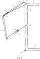
- Fig. 7 shows the side wall according to the invention in a partially opened state
- Handlebar 13 using a telescopic arrangement e.g. a spring 24 or the like in its Length is adjustable.
- the handlebar 13 In the open position of the side wall, the handlebar 13 has its minimal length on
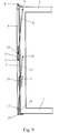
- Fig. 9 shows the side wall of the vehicle when fully closed.
- the handlebar 13 has its maximum length, i.e. the spring 24 is stretched to the maximum.
- the side wall 4, 5 is securely closed without additional closing means, such as. Hook or bolt possible.
- the feature according to the invention can also be realized by other measures, which cause a change in length of the handlebar 13.
- the one shown in Figs. 7-9 Spring 24 or similar arrangements for changing the length of the handlebar 13 do not have to lie within the handlebar 13.
- Fig. 10 schematically shows an embodiment of the invention at the point of application 12 of the handlebar 13, which comprises a guide 25 in the lower wall part 5 and a spring 26 or the like.
- a force acting on the spring 26 takes place and this is thereby compressed and an apparent extension of the handlebar 13 takes place.
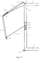
- the Handlebar 13 may be provided on the vertical part 3 of the vehicle body. The 11 has the advantage over the variant from FIG. 10 that that usually more space on the vehicle body to accommodate the arrangement for resilient Slidability exists.
- the resilient change in length of the handlebar 13 and the resilient displaceability of the Ends or related elements of the handlebar can of course by various measures, such as Coil springs, gas springs, hydraulic springs, elastic materials or similar. be realized and is not based on the above or in methods outlined in the drawings.
- Fig. 12a is a schematic side view of a truck with the side wall according to the invention consisting of the upper wall part 4 and the lower Wall part 5 and an underride guard 29 shown. 12b, the underride guard 29 shown in detail in the open position.
- the underride guard 29 consists essentially from a stand 30, which is attached to the vehicle body and a foldable part 35, the serves as a platform.
- the mechanism for opening the Underrun protection from screws, bolts or the like. 31, 32, which are on the side of the upright 30 are attached. Due to the special design of a bracket 33 mounted on the platform 35 secure anchoring in the raised position while driving is guaranteed and simple opening by lifting the platform 35 possible.
- the Platform 35 attached handle or the like can facilitate lifting will.
- the platform 35 of the underrun protection 29 is closed by a Flat iron 34 held in a horizontal position and can therefore be used as stairs.
- the side wall according to the invention which can be opened upwards can be used with With the help of the underride guard, which can be used as stairs, loading and unloading the vehicle be made much easier.
Landscapes
- Engineering & Computer Science (AREA)
- Mechanical Engineering (AREA)
- Body Structure For Vehicles (AREA)
- Air Bags (AREA)
- Magnetic Heads (AREA)
- Transplanting Machines (AREA)
- Vehicle Interior And Exterior Ornaments, Soundproofing, And Insulation (AREA)
- Window Of Vehicle (AREA)
- Harvesting Machines For Specific Crops (AREA)
- Steering Devices For Bicycles And Motorcycles (AREA)
- Vehicle Cleaning, Maintenance, Repair, Refitting, And Outriggers (AREA)
- Vehicle Step Arrangements And Article Storage (AREA)
Priority Applications (10)
| Application Number | Priority Date | Filing Date | Title |
|---|---|---|---|
| NZ319516A NZ319516A (en) | 1996-03-21 | 1996-10-17 | Vehicle side wall comprising two wall portions for closing a loading opening and occupying a location above the roof of the vehicle body |
| PL96330861A PL182228B1 (pl) | 1996-03-21 | 1996-10-17 | Scianka boczna nadwozia pojazdu PL |
| PCT/AT1996/000200 WO1997034793A1 (de) | 1996-03-21 | 1996-10-17 | Seitenwand für den aufbau eines fahrzeuges |
| US09/091,159 US6079762A (en) | 1996-03-21 | 1996-10-17 | Side wall for a vehicle body |
| HU9903523A HU222207B1 (hu) | 1996-03-21 | 1996-10-17 | Oldalfal egy jármű felépítményéhez |
| JP52154197A JP3382952B2 (ja) | 1996-03-21 | 1996-10-17 | 車体側壁 |
| CA002242613A CA2242613C (en) | 1996-03-21 | 1996-10-17 | Side wall for a vehicle body |
| BR9611042A BR9611042A (pt) | 1996-03-21 | 1996-10-17 | Parede lateral para a montagem de um veículo |
| AU72059/96A AU711371B2 (en) | 1996-03-21 | 1996-10-17 | Side wall for the body of a vehicle |
| NO19982693A NO310452B1 (no) | 1996-03-21 | 1998-06-11 | Sidevegg for overbygningen på et kjöretöy |
Applications Claiming Priority (4)
| Application Number | Priority Date | Filing Date | Title |
|---|---|---|---|
| AT682/95 | 1995-04-21 | ||
| AT68295A AT402723B (de) | 1995-04-21 | 1995-04-21 | Seitenwand für den aufbau eines fahrzeuges |
| AT527/96 | 1996-03-21 | ||
| AT0052796A AT404011B (de) | 1996-03-21 | 1996-03-21 | Seitenwand für den aufbau eines fahrzeuges |
Publications (3)
| Publication Number | Publication Date |
|---|---|
| EP0738649A2 EP0738649A2 (de) | 1996-10-23 |
| EP0738649A3 EP0738649A3 (de) | 1997-01-22 |
| EP0738649B1 true EP0738649B1 (de) | 1998-09-02 |
Family
ID=25593042
Family Applications (1)
| Application Number | Title | Priority Date | Filing Date |
|---|---|---|---|
| EP96890070A Expired - Lifetime EP0738649B1 (de) | 1995-04-21 | 1996-04-18 | Seitenwand für Fahrzeuge |
Country Status (5)
| Country | Link |
|---|---|
| EP (1) | EP0738649B1 (da) |
| AT (1) | ATE170474T1 (da) |
| DE (1) | DE59600498D1 (da) |
| DK (1) | DK0738649T3 (da) |
| ES (1) | ES2124075T3 (da) |
Cited By (2)
| Publication number | Priority date | Publication date | Assignee | Title |
|---|---|---|---|---|
| WO2006079137A1 (de) | 2005-01-31 | 2006-08-03 | Johann Sen Strasser | Vorrichtung zum überführen der wand eines transportbehälters zwischen einer schliessstellung und einer offenstellung und transportbehälter |
| DE102010051428A1 (de) | 2010-11-17 | 2012-05-24 | Kramer Fahrzeugtechnik Gmbh & Co. Kg | Vorrichtung zum Bewegen einer Wand eines Transportbehälters |
Families Citing this family (4)
| Publication number | Priority date | Publication date | Assignee | Title |
|---|---|---|---|---|
| DE10015545C2 (de) * | 2000-03-30 | 2003-12-04 | Mms Multimodalsysteme Ag Pfaef | Wechselbehälter |
| DE102006053523B3 (de) * | 2006-11-07 | 2008-01-31 | Orten Karlsdorf-Neuthard Gmbh & Co. Kg | Vorrichtung zum Überführen einer Wand eines Transportbehälters zwischen einer Schliessstellung und einer Offenstellung und Transportbehälter |
| AT12177U1 (de) | 2010-02-09 | 2011-12-15 | Strasser Johann Sen | Transportbehälter |
| EP2383206A1 (en) * | 2010-04-28 | 2011-11-02 | Hyva International B.V. | Container or vehicle body and a drive unit for its side door |
Citations (1)
| Publication number | Priority date | Publication date | Assignee | Title |
|---|---|---|---|---|
| DE9108949U1 (de) * | 1991-07-20 | 1991-11-28 | Zikun - Fahrzeugbau GmbH, 7839 Riegel | Klappwandaufbau für Nutzfahrzeuge, Container o.ä. Transportbehälter |
Family Cites Families (9)
| Publication number | Priority date | Publication date | Assignee | Title |
|---|---|---|---|---|
| BE719007A (da) * | 1968-08-02 | 1969-01-16 | ||
| BE744868A (nl) * | 1970-01-23 | 1970-07-01 | Vanassche Polidoor V A J | Voertuig, |
| DE2638972C2 (de) * | 1976-08-28 | 1987-04-02 | F.X. Kögel GmbH & Co, 7900 Ulm | Kofferaufbau für Lastfahrzeuge, wie Lastwagen, Anhänger, Sattelaufbauten usw. |
| DE2809375A1 (de) * | 1978-03-04 | 1979-09-13 | Guenter Peters | Lastkraftwagen mit ladepritsche und aufbau |
| DE2919608A1 (de) * | 1979-05-16 | 1980-11-20 | Guenter Peters | Lastkraftwagen mit ladepritsche und aufbau |
| DE3046178A1 (de) * | 1980-12-08 | 1982-07-15 | Heinz Böse KG, 5779 Eslohe | "aufbau eines lastkraftwagens oder anhaengers" |
| DE3102891A1 (de) * | 1981-01-29 | 1982-08-26 | Dieter 4518 Bad Laer Köster | "fahrzeugaufbau mit einer tuerklappe" |
| DE9218398U1 (de) * | 1992-11-06 | 1994-02-10 | Robert Orten GmbH & Co., 54470 Bernkastel-Kues | Verschlußvorrichtung |
| FR2710019B1 (fr) * | 1993-09-17 | 1995-12-08 | Gerard Grosse | Caisse à parois latérales relevables pour véhicule de transport routier et véhicule équipé d'une telle caisse. |
-
1996
- 1996-04-18 AT AT96890070T patent/ATE170474T1/de active
- 1996-04-18 EP EP96890070A patent/EP0738649B1/de not_active Expired - Lifetime
- 1996-04-18 ES ES96890070T patent/ES2124075T3/es not_active Expired - Lifetime
- 1996-04-18 DK DK96890070T patent/DK0738649T3/da active
- 1996-04-18 DE DE59600498T patent/DE59600498D1/de not_active Expired - Lifetime
Patent Citations (1)
| Publication number | Priority date | Publication date | Assignee | Title |
|---|---|---|---|---|
| DE9108949U1 (de) * | 1991-07-20 | 1991-11-28 | Zikun - Fahrzeugbau GmbH, 7839 Riegel | Klappwandaufbau für Nutzfahrzeuge, Container o.ä. Transportbehälter |
Cited By (3)
| Publication number | Priority date | Publication date | Assignee | Title |
|---|---|---|---|---|
| WO2006079137A1 (de) | 2005-01-31 | 2006-08-03 | Johann Sen Strasser | Vorrichtung zum überführen der wand eines transportbehälters zwischen einer schliessstellung und einer offenstellung und transportbehälter |
| DE102010051428A1 (de) | 2010-11-17 | 2012-05-24 | Kramer Fahrzeugtechnik Gmbh & Co. Kg | Vorrichtung zum Bewegen einer Wand eines Transportbehälters |
| DE102010051428B4 (de) * | 2010-11-17 | 2012-06-06 | Kramer Fahrzeugtechnik Gmbh & Co. Kg | Vorrichtung zum Bewegen einer Wand eines Transportbehälters |
Also Published As
| Publication number | Publication date |
|---|---|
| EP0738649A2 (de) | 1996-10-23 |
| DK0738649T3 (da) | 1999-06-07 |
| ATE170474T1 (de) | 1998-09-15 |
| ES2124075T3 (es) | 1999-01-16 |
| EP0738649A3 (de) | 1997-01-22 |
| DE59600498D1 (de) | 1998-10-08 |
Similar Documents
| Publication | Publication Date | Title |
|---|---|---|
| WO1997034793A1 (de) | Seitenwand für den aufbau eines fahrzeuges | |
| DE2640317C2 (de) | Fahrzeugtür | |
| EP1332918A2 (de) | Kraftfahrzeug mit einem verlängebarem Laderaum und einer Laderaumtür | |
| DE2620683C3 (de) | Einstieganordnung für ein Nahverkehrsfahrzeug, insbesondere Schienenfahrzeug | |
| DE102016202395B3 (de) | Personenkraftfahrzeug mit einer Seitentür | |
| DE10155220C1 (de) | Türanordnung für Kraftfahrzeuge | |
| EP0893302A2 (de) | Ausziehbarer Ladeboden für ein Fahrzeug | |
| DE60133543T2 (de) | Versenkbares starres dachsystem für cabriofahrzeug | |
| DE3236034C2 (de) | Schwenkbares Fahrzeugdach | |
| DE10203539B4 (de) | Kraftfahrzeug mit einem Laderaum und einer Laderaumtür | |
| DE3828184A1 (de) | Karosserieanordnung fuer ein kraftfahrzeug oder einen anhaenger | |
| EP3118058B1 (de) | Fahrzeugaufbau | |
| DE2830192A1 (de) | Fahrzeugtuer, insbesondere fuer gewerbliche kraftfahrzeuge | |
| DE202011050733U1 (de) | Mobile Arbeitsmaschine mit höhenbeweglichem Fahrerschutz | |
| EP0738649A2 (de) | Seitenwand für Fahrzeuge | |
| AT501549B1 (de) | Trittstufenantrieb | |
| EP1843909A1 (de) | Vorrichtung zum überführen der wand eines transportbehälters zwischen einer schliessstellung und einer offenstellung und transportbehälter | |
| EP3558731B1 (de) | Hecktür von aufbauten von lkws oder lkw-anhängern | |
| DE29519026U1 (de) | Geteilte Heckklappe für Kraftfahrzeuge | |
| AT402723B (de) | Seitenwand für den aufbau eines fahrzeuges | |
| DE4006532A1 (de) | Ladepritsche fuer fahrzeug mit wenigstens einer oeffenbaren seitenwand | |
| DE4136895C1 (en) | Folding roof for motor vehicle - has linkage outside swivel path of roof cover bow | |
| DE2318614C3 (de) | Einstiegsverkleidung an Wetterverdecken und Fahrerhäusern von Nutzfahrzeugen | |
| DE19544781A1 (de) | Geteilte Heckklappe für Kraftfahrzeuge | |
| AT404011B (de) | Seitenwand für den aufbau eines fahrzeuges |
Legal Events
| Date | Code | Title | Description |
|---|---|---|---|
| PUAI | Public reference made under article 153(3) epc to a published international application that has entered the european phase |
Free format text: ORIGINAL CODE: 0009012 |
|
| AK | Designated contracting states |
Kind code of ref document: A2 Designated state(s): AT BE CH DE DK ES FI FR GB GR IE IT LI LU MC NL PT SE |
|
| PUAL | Search report despatched |
Free format text: ORIGINAL CODE: 0009013 |
|
| AK | Designated contracting states |
Kind code of ref document: A3 Designated state(s): AT BE CH DE DK ES FI FR GB GR IE IT LI LU MC NL PT SE |
|
| 17P | Request for examination filed |
Effective date: 19970225 |
|
| 17Q | First examination report despatched |
Effective date: 19970506 |
|
| TPAD | Observations filed by third parties |
Free format text: ORIGINAL CODE: EPIDOS TIPA |
|
| GRAG | Despatch of communication of intention to grant |
Free format text: ORIGINAL CODE: EPIDOS AGRA |
|
| GRAG | Despatch of communication of intention to grant |
Free format text: ORIGINAL CODE: EPIDOS AGRA |
|
| GRAH | Despatch of communication of intention to grant a patent |
Free format text: ORIGINAL CODE: EPIDOS IGRA |
|
| GRAH | Despatch of communication of intention to grant a patent |
Free format text: ORIGINAL CODE: EPIDOS IGRA |
|
| GRAH | Despatch of communication of intention to grant a patent |
Free format text: ORIGINAL CODE: EPIDOS IGRA |
|
| GRAA | (expected) grant |
Free format text: ORIGINAL CODE: 0009210 |
|
| AK | Designated contracting states |
Kind code of ref document: B1 Designated state(s): AT BE CH DE DK ES FI FR GB GR IE IT LI LU MC NL PT SE |
|
| PG25 | Lapsed in a contracting state [announced via postgrant information from national office to epo] |
Ref country code: GR Free format text: LAPSE BECAUSE OF NON-PAYMENT OF DUE FEES Effective date: 19980902 |
|
| REF | Corresponds to: |
Ref document number: 170474 Country of ref document: AT Date of ref document: 19980915 Kind code of ref document: T |
|
| REG | Reference to a national code |
Ref country code: CH Ref legal event code: EP |
|
| REF | Corresponds to: |
Ref document number: 59600498 Country of ref document: DE Date of ref document: 19981008 |
|
| REG | Reference to a national code |
Ref country code: CH Ref legal event code: NV Representative=s name: ROTTMANN, ZIMMERMANN + PARTNER AG |
|
| REG | Reference to a national code |
Ref country code: IE Ref legal event code: FG4D Free format text: GERMAN |
|
| ET | Fr: translation filed | ||
| REG | Reference to a national code |
Ref country code: ES Ref legal event code: FG2A Ref document number: 2124075 Country of ref document: ES Kind code of ref document: T3 |
|
| REG | Reference to a national code |
Ref country code: PT Ref legal event code: SC4A Free format text: AVAILABILITY OF NATIONAL TRANSLATION Effective date: 19981016 |
|
| GBT | Gb: translation of ep patent filed (gb section 77(6)(a)/1977) |
Effective date: 19990112 |
|
| PG25 | Lapsed in a contracting state [announced via postgrant information from national office to epo] |
Ref country code: LU Free format text: LAPSE BECAUSE OF NON-PAYMENT OF DUE FEES Effective date: 19990418 |
|
| REG | Reference to a national code |
Ref country code: DK Ref legal event code: T3 |
|
| PLBE | No opposition filed within time limit |
Free format text: ORIGINAL CODE: 0009261 |
|
| STAA | Information on the status of an ep patent application or granted ep patent |
Free format text: STATUS: NO OPPOSITION FILED WITHIN TIME LIMIT |
|
| 26N | No opposition filed | ||
| PG25 | Lapsed in a contracting state [announced via postgrant information from national office to epo] |
Ref country code: MC Free format text: LAPSE BECAUSE OF NON-PAYMENT OF DUE FEES Effective date: 19991031 |
|
| REG | Reference to a national code |
Ref country code: GB Ref legal event code: IF02 |
|
| PGFP | Annual fee paid to national office [announced via postgrant information from national office to epo] |
Ref country code: PT Payment date: 20100323 Year of fee payment: 15 Ref country code: IE Payment date: 20100329 Year of fee payment: 15 |
|
| REG | Reference to a national code |
Ref country code: CH Ref legal event code: PFA Owner name: STRASSER, JOHANN Free format text: STRASSER, JOHANN#BAHNWEG 1#5301 EUGENDORF (AT) -TRANSFER TO- STRASSER, JOHANN#BAHNWEG 1#5301 EUGENDORF (AT) |
|
| REG | Reference to a national code |
Ref country code: PT Ref legal event code: MM4A Free format text: LAPSE DUE TO NON-PAYMENT OF FEES Effective date: 20111018 |
|
| PG25 | Lapsed in a contracting state [announced via postgrant information from national office to epo] |
Ref country code: PT Free format text: LAPSE BECAUSE OF NON-PAYMENT OF DUE FEES Effective date: 20111018 |
|
| REG | Reference to a national code |
Ref country code: IE Ref legal event code: MM4A |
|
| PG25 | Lapsed in a contracting state [announced via postgrant information from national office to epo] |
Ref country code: IE Free format text: LAPSE BECAUSE OF NON-PAYMENT OF DUE FEES Effective date: 20110418 |
|
| REG | Reference to a national code |
Ref country code: FR Ref legal event code: PLFP Year of fee payment: 20 |
|
| PGFP | Annual fee paid to national office [announced via postgrant information from national office to epo] |
Ref country code: GB Payment date: 20150410 Year of fee payment: 20 Ref country code: CH Payment date: 20150427 Year of fee payment: 20 Ref country code: SE Payment date: 20150429 Year of fee payment: 20 Ref country code: DK Payment date: 20150417 Year of fee payment: 20 Ref country code: DE Payment date: 20150430 Year of fee payment: 20 Ref country code: ES Payment date: 20150416 Year of fee payment: 20 Ref country code: FI Payment date: 20150413 Year of fee payment: 20 |
|
| REG | Reference to a national code |
Ref country code: DE Ref legal event code: R082 Ref document number: 59600498 Country of ref document: DE Representative=s name: GRAMM, LINS & PARTNER PATENT- UND RECHTSANWAEL, DE |
|
| PGFP | Annual fee paid to national office [announced via postgrant information from national office to epo] |
Ref country code: BE Payment date: 20150429 Year of fee payment: 20 Ref country code: NL Payment date: 20150429 Year of fee payment: 20 Ref country code: FR Payment date: 20150410 Year of fee payment: 20 Ref country code: IT Payment date: 20150429 Year of fee payment: 20 Ref country code: AT Payment date: 20150424 Year of fee payment: 20 |
|
| REG | Reference to a national code |
Ref country code: DE Ref legal event code: R071 Ref document number: 59600498 Country of ref document: DE |
|
| REG | Reference to a national code |
Ref country code: NL Ref legal event code: MK Effective date: 20160417 |
|
| REG | Reference to a national code |
Ref country code: DK Ref legal event code: EUP Effective date: 20160418 |
|
| REG | Reference to a national code |
Ref country code: CH Ref legal event code: PL |
|
| REG | Reference to a national code |
Ref country code: GB Ref legal event code: PE20 Expiry date: 20160417 |
|
| REG | Reference to a national code |
Ref country code: SE Ref legal event code: EUG |
|
| REG | Reference to a national code |
Ref country code: AT Ref legal event code: MK07 Ref document number: 170474 Country of ref document: AT Kind code of ref document: T Effective date: 20160418 |
|
| REG | Reference to a national code |
Ref country code: ES Ref legal event code: FD2A Effective date: 20160727 |
|
| PG25 | Lapsed in a contracting state [announced via postgrant information from national office to epo] |
Ref country code: GB Free format text: LAPSE BECAUSE OF EXPIRATION OF PROTECTION Effective date: 20160417 |
|
| PG25 | Lapsed in a contracting state [announced via postgrant information from national office to epo] |
Ref country code: ES Free format text: LAPSE BECAUSE OF EXPIRATION OF PROTECTION Effective date: 20160419 |