EP0738544A1 - Transporteur pour trier des articles - Google Patents
Transporteur pour trier des articles Download PDFInfo
- Publication number
- EP0738544A1 EP0738544A1 EP96105623A EP96105623A EP0738544A1 EP 0738544 A1 EP0738544 A1 EP 0738544A1 EP 96105623 A EP96105623 A EP 96105623A EP 96105623 A EP96105623 A EP 96105623A EP 0738544 A1 EP0738544 A1 EP 0738544A1
- Authority
- EP
- European Patent Office
- Prior art keywords
- conveyor
- general cargo
- trays
- activated
- conveyor according
- Prior art date
- Legal status (The legal status is an assumption and is not a legal conclusion. Google has not performed a legal analysis and makes no representation as to the accuracy of the status listed.)
- Withdrawn
Links
Images


Classifications
-
- B—PERFORMING OPERATIONS; TRANSPORTING
- B07—SEPARATING SOLIDS FROM SOLIDS; SORTING
- B07C—POSTAL SORTING; SORTING INDIVIDUAL ARTICLES, OR BULK MATERIAL FIT TO BE SORTED PIECE-MEAL, e.g. BY PICKING
- B07C3/00—Sorting according to destination
- B07C3/02—Apparatus characterised by the means used for distribution
- B07C3/06—Linear sorting machines in which articles are removed from a stream at selected points
-
- B—PERFORMING OPERATIONS; TRANSPORTING
- B07—SEPARATING SOLIDS FROM SOLIDS; SORTING
- B07C—POSTAL SORTING; SORTING INDIVIDUAL ARTICLES, OR BULK MATERIAL FIT TO BE SORTED PIECE-MEAL, e.g. BY PICKING
- B07C3/00—Sorting according to destination
- B07C3/02—Apparatus characterised by the means used for distribution
- B07C3/08—Apparatus characterised by the means used for distribution using arrangements of conveyors
- B07C3/082—In which the objects are carried by transport holders and the transport holders form part of the conveyor belts
-
- B—PERFORMING OPERATIONS; TRANSPORTING
- B65—CONVEYING; PACKING; STORING; HANDLING THIN OR FILAMENTARY MATERIAL
- B65G—TRANSPORT OR STORAGE DEVICES, e.g. CONVEYORS FOR LOADING OR TIPPING, SHOP CONVEYOR SYSTEMS OR PNEUMATIC TUBE CONVEYORS
- B65G47/00—Article or material-handling devices associated with conveyors; Methods employing such devices
- B65G47/34—Devices for discharging articles or materials from conveyor
Definitions
- the invention relates to a piece goods conveyor, also referred to as a sorter, for sorting piece goods parts, in particular relatively flat piece goods parts of the same type, such as letters, magazines, books, CDs, video tapes and the like, with a driven, endlessly revolving conveyor line which consists of a plurality of articulated interconnected, guided on a guide conveyor elements, each having a support base for supporting a piece of goods to be delivered at a predetermined delivery point, which is provided with through-going through-going slots that extend from its front section in the conveying direction to its rear edge; with at least one loading point at which piece goods to be sorted are to be individually loaded onto the supporting floor of a free conveying element; and with a plurality of delivery points (end points) provided along the conveying path, at each of which a wiping device which can be activated by a control device is arranged, by means of which, in an activated wiping position, a piece of conveyed part conveyed from the supporting floor of a conveying element passing the
- Sorters of various designs are increasingly being used for automated handling of piece goods in order to selectively discharge piece goods parts that have been put in by hand or by means of feed devices, with appropriate sorting, at one of several delivery points.
- Typical applications are the sorting of parcels at the post office or the sorting of luggage at airports, but there are also a multitude of other possible uses, such as in mail order companies, publishers, etc.
- the general cargo parts are generally coded accordingly. Your code is read by a reading device after its task on the supporting floor of a conveying element, and the corresponding data are put into a computer, from which the control device then receives a discharge signal at the appropriate time, which causes the piece goods part to be delivered to the intended delivery point .
- the conveyor line or the like from a continuous belt conveyor. is formed, from which the general cargo parts are discharged at the intended delivery point with a plunger (puscher) acting transversely to the conveying direction
- the conveyor line is generally designed as a link conveyor with a large number of articulated conveyor elements, the support base of which is generally Part of a tilting element, which is to be tilted sideways at the intended delivery point in order to discharge the piece goods part supported by the supporting floor.
- Numerous different configurations are known for this, in order to be able to achieve a precise and as gentle as possible discharge.
- sorters are known in which, as already stated, the piece goods parts at the intended loading point are laterally by a (generally stationary) Ram pushed off or stripped to the side by means of traveling scenes (EP 0 626 324 A1) or swiveling scraper (DE 39 18 196 C1).
- a comb-shaped scraper is moved so far downwards by means of a scraper drive that its scraper tines extend into the path of movement of the trays and, when passing through the conveying element, each reach into a slot in its trays in order to scrap the piece of goods lying thereon from the tray on its rear edge .
- the scraper is then immediately moved back into its non-activated rest position, unless the piece goods part conveyed by the subsequent conveying element is also to be delivered at this delivery point.
- Another disadvantage of the known generic sorter is that a hand-in of piece goods is not possible without risk immediately in front of a delivery point, since it can result in a hand being caught between a conveyor element approaching a delivery point and the stripping device of the delivery point if the hand a person giving up general cargo is not withdrawn in good time before the conveying element passes the stripping device.
- the present invention has for its object to improve a generic sorter in particular in that a task of general cargo parts at any point, that is also possible where there is a delivery point, that is the largest possible number regardless of the number and positioning of the posting points of delivery points is to be realized, while at the same time a safe manual task of general cargo parts is to be guaranteed at any point of the sorter.
- the stripping devices are arranged below the trays, the scraper prongs of an activated scraper projecting upward beyond the top of the trays of a tray passing through the stripping device in question.
- a preferred embodiment of the present invention is that the trays of the conveying elements are arranged offset, transversely to the central axis of the continuous conveyor, and at the most preferably so far laterally offset that they protrude freely over the supporting structure.
- the overall height of the sorter is evidently not increased by the scraper devices, and there is not only sufficient space available below the laterally protruding supporting floors to accommodate the scraper devices in an expedient manner, but also sufficient space for receiving devices for receiving of the discharged general cargo parts, whereby the delivery and reception (e.g. in containers) is particularly unproblematic and therefore extremely useful, because a distributed general cargo part does not need to be moved to the side after stripping from a supporting floor, but can fall freely.
- two support floors are arranged on each conveyor element in mirror symmetry with the central axis of the general cargo conveyor, i.e. one support floor on the outside and a second support floor on the inside of the sorter, which means that the sorter capacity is to be doubled.
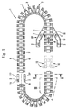
- Fig. 1 shows a simplified representation of a plan view of a sorter designated 1 as a whole for sorting flat, same-sized piece goods 2, such as letters.
- the endless circulating conveyor line of the sorter 1 exists from a plurality of articulated conveyor elements 3, which are guided by rollers 4 on a guide 5 designed as a double rail (FIG. 2), which form the essential part of the supporting structure and are supported on the ground (not shown). It is driven by a linear motor 22.
- the conveying elements 3 each have two trays 6, which are arranged so far laterally offset transversely to the central axis 7 of the sorter 1 that they protrude freely outside and inside over its supporting structure (see FIG. 2).
- Each support base 6 is provided with through-slots 9 running in the conveying direction 8 (see in particular FIG. 3), which extend from its section lying at the front in the conveying direction 8 to its rear edge 10.
- two feed points 11 are indicated by way of example, which are arranged as feed devices 11 'with overhead loading and are assigned on the one hand to the inner support floors 6 and on the other hand to the outer support floors 6.
- the general cargo parts 2 are currently in the waiting position.
- the sorter 1 has not yet been loaded with general cargo parts 2.
- Feed points 11 are also indicated by way of example at the bottom right in FIG. 1, which are realized by feed devices 11 'with side introduction.
- the feed devices 11 ' are synchronized with the sorter 1 such that the piece goods parts 2 can each be properly placed on a free conveying element 3, as described for example in EP 0 366 857. Further feed points 11 have been omitted in FIG. 1 for the sake of a better overview.
- a large number of delivery points 12 are located along the conveyor route provided, of which only a few delivery points 12 are indicated in the lower middle region of FIG. 1.
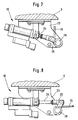
- a wiping device 13 to be activated by a control device is arranged below the trays 6 (see FIGS. 2-8), which is freely passable by the piece goods parts 2 in their normal, non-activated operating position, and by means of which, in its activated stripping position, is to strip a supplied piece of bulk goods 2 at the respective delivery point 12 from the supporting floor 6 of the conveying element 3 in question via its rear edge 10 and thus to be discharged downwards, as will be explained in more detail below.
- the stripping devices 13 each have a comb-shaped stripper 14, the stripping tines 15 of which are aligned in the conveying direction 8 with the slots 9 of the trays 6 have the same pitch as the slots 9 of the trays 6 and have a somewhat smaller width than the slot width.
- the wipers 14 After receiving a corresponding control signal, the wipers 14 are swiveled upwards from their inactive rest position (see, for example, FIG. 2, right) into their wiping position (see, for example, FIG.
- a swivel drive 16 in which the wiping tines 15 extend so far extend the path of movement of the trays 6 such that they each engage in a slot 9 of a trays 6 passing through the activated stripping device 13 and protrude upwards over the top of a trays passing through the stripping device 13 in question.
- the swivel drives 16 are each designed as a rotary magnet.
- the swivel drives 16 each consist of a pneumatic piston-cylinder unit which is fastened with a bracket 23 to the underside of the corresponding guide 5, and the piston rod 24 of which is articulated via a lever 25 with a swivel-mounted stripper shaft 26 of which the scraper tines are connected 15 protrude at right angles.
- the trays 6 are chamfered at their front section 17 lying at the front in the conveying direction 8 at an acute angle and provided with a cross member 18 at their front edge.
- the trays 6 On their inside, the trays 6 have an inner wall 19 against which a piece of general cargo 2 can rest after its task. In order to ensure this, the trays 6 can each be arranged inclined from the outside to the inside.
- FIG. 4 shows the loading of a free conveying element 3 by means of a feed device 11 ′ arranged at a feed point 11.
- the feed device 11 'synchronized with the sorter 1 is activated after receiving a corresponding signal in such a way that the piece goods part 2 in question is placed on the support base 6 of the conveying element 3 in question in the manner shown in FIG. It therefore tilts down over the front edge of the feed device 11 'when the conveying element 3 in question moves past the feed device 11', and finally rests on its support base 6, as can be seen in the upper left part of FIG. 5. Furthermore, it can be seen in Fig.
- this feed point 11 is also a delivery or end point 12, since a stripping device 13 is also arranged at this feed point 11 below the trays 6, which is in an inactive position in which the scraper tines 15 are pivoted downwards from the relevant swivel drive 16, so that the next supplied piece goods part 2 can freely pass this delivery point 12, but any subsequent conveying element 3 can, if necessary, discharge the piece goods part 2 carried there when the stripping device 13 is activated.
- a removal is also based on the 5, which is shown schematically and in simplified form for the sake of clarity, shows a side view of a section of the sorter 1 with three successive conveying elements 3.1, 3.2 and 3.3, the mutual connection of which has been omitted for the sake of clarity, as have the other components of the sorter 1 which are irrelevant for the discharge of a general cargo part 2.
- FIG. 9 shows a plan view of a conveying element 3, which has a support base 6 with a length L on its outside and two support bases 6 with a smaller length 1 on its inside.
- a conveying element 3 which has a support base 6 with a length L on its outside and two support bases 6 with a smaller length 1 on its inside.
- Such a configuration is useful if 1 piece goods parts 2 of different types and with a sorter Length are to be sorted, for example magazines on the one hand and CDs on the other, with a first type of general cargo being sorted on the outside and the other type of general cargo on the inside of sorter 1.
- the beveling of the trays 6 on their front section 17 is not only expedient for the desired positioning of a general cargo part 2 on a trays 6, but that the front outside of this section 17 also forms a sliding surface on which one of a scraper 14 is guided downward by the piece goods part 2 stripped off in the direction of conveyance 8 adjacent to the support base 6 if it is correspondingly long or if the distance between two successive support bases 6 is relatively small.
Landscapes
- Engineering & Computer Science (AREA)
- Mechanical Engineering (AREA)
- Branching, Merging, And Special Transfer Between Conveyors (AREA)
Applications Claiming Priority (2)
| Application Number | Priority Date | Filing Date | Title |
|---|---|---|---|
| DE1995114373 DE19514373A1 (de) | 1995-04-18 | 1995-04-18 | Stückgutförderer zum Sortieren von Stückgutteilen |
| DE19514373 | 1995-04-18 |
Publications (1)
| Publication Number | Publication Date |
|---|---|
| EP0738544A1 true EP0738544A1 (fr) | 1996-10-23 |
Family
ID=7759855
Family Applications (1)
| Application Number | Title | Priority Date | Filing Date |
|---|---|---|---|
| EP96105623A Withdrawn EP0738544A1 (fr) | 1995-04-18 | 1996-04-10 | Transporteur pour trier des articles |
Country Status (2)
| Country | Link |
|---|---|
| EP (1) | EP0738544A1 (fr) |
| DE (1) | DE19514373A1 (fr) |
Cited By (2)
| Publication number | Priority date | Publication date | Assignee | Title |
|---|---|---|---|---|
| ES2164501A1 (es) * | 1998-06-24 | 2002-02-16 | Ct De Estudios Y Desarrollos I | Maquina clasificadora automatica de sobres y pequeña paqueteria. |
| WO2006053570A1 (fr) * | 2004-11-22 | 2006-05-26 | Fki Logistex A/S | Appareil et procede de transport/tri |
Citations (3)
| Publication number | Priority date | Publication date | Assignee | Title |
|---|---|---|---|---|
| US3148783A (en) * | 1961-11-20 | 1964-09-15 | Fmc Corp | Apparatus for sorting articles |
| FR2645774A1 (fr) * | 1989-04-13 | 1990-10-19 | Cybernetix | Perfectionnement a des dispositifs de convoyage et de tri d'objets plats heterogenes |
| EP0640409A2 (fr) * | 1993-08-30 | 1995-03-01 | Electrocom Gard Ltd. | Trieuse de petits documents plats |
-
1995
- 1995-04-18 DE DE1995114373 patent/DE19514373A1/de not_active Withdrawn
-
1996
- 1996-04-10 EP EP96105623A patent/EP0738544A1/fr not_active Withdrawn
Patent Citations (3)
| Publication number | Priority date | Publication date | Assignee | Title |
|---|---|---|---|---|
| US3148783A (en) * | 1961-11-20 | 1964-09-15 | Fmc Corp | Apparatus for sorting articles |
| FR2645774A1 (fr) * | 1989-04-13 | 1990-10-19 | Cybernetix | Perfectionnement a des dispositifs de convoyage et de tri d'objets plats heterogenes |
| EP0640409A2 (fr) * | 1993-08-30 | 1995-03-01 | Electrocom Gard Ltd. | Trieuse de petits documents plats |
Cited By (2)
| Publication number | Priority date | Publication date | Assignee | Title |
|---|---|---|---|---|
| ES2164501A1 (es) * | 1998-06-24 | 2002-02-16 | Ct De Estudios Y Desarrollos I | Maquina clasificadora automatica de sobres y pequeña paqueteria. |
| WO2006053570A1 (fr) * | 2004-11-22 | 2006-05-26 | Fki Logistex A/S | Appareil et procede de transport/tri |
Also Published As
| Publication number | Publication date |
|---|---|
| DE19514373A1 (de) | 1996-10-24 |
Similar Documents
| Publication | Publication Date | Title |
|---|---|---|
| DE102008036564B4 (de) | Skalierbarer Versandpuffer mit integrierter Sortierfunktion und Verfahren dazu | |
| DE19854629B4 (de) | Automatisiertes Lager | |
| EP0286080B1 (fr) | Dispositif pour diriger le transfert d'objets | |
| EP0732279B1 (fr) | Système de stockage d'articles | |
| EP3281891A1 (fr) | Système de transfert comprenant un dispositif de poussée pour marchandises au détail | |
| EP3335201B1 (fr) | Dispositif de défournement de produits de boulangerie-pâtisserie | |
| EP3623061B1 (fr) | Installation de tri et procédé de tri d'objets | |
| EP3246272B1 (fr) | Glissière et dispositif de tri et procédé de tri de marchandise au détail | |
| DE2611556A1 (de) | Automatisches sortierfoerdersystem | |
| DE202004021388U1 (de) | Kommissionierplatz | |
| EP1115638B1 (fr) | Dispositif de distribution pour articles individuels | |
| DE3530624A1 (de) | Einrichtung zum sortieren von gegenstaenden wie schriftstuecke o.ae. flachgut, paeckchen od. dgl. kleineres stueckgut usw. | |
| EP0581398B1 (fr) | Porte-charges et dispositif pour leur vidange | |
| EP3377427A1 (fr) | Système de transport | |
| EP3303196B1 (fr) | Transporteur à chute gravitaire pourvu d'un dispositif de répartition sur la largeur | |
| EP3450355B1 (fr) | Installation de transport | |
| DE2211793B2 (de) | Vorrichtung zum bereitstellen von gefaessen | |
| DE19501637C2 (de) | Palettiervorrichtung | |
| EP3623060A1 (fr) | Procédé de tri d'objets ainsi qu'installation de tri | |
| EP0825284A2 (fr) | Transporteur sans fin | |
| EP3676205B1 (fr) | Procédé et dispositif servant à transférer des articles à convoyer entre deux dispositifs de convoyage, ainsi que système de convoyage | |
| EP0738544A1 (fr) | Transporteur pour trier des articles | |
| EP2174897B1 (fr) | Dispositif de guidage de bouteilles consignées | |
| DE10232215A1 (de) | Fördereinrichtung zum Transport und Ausschleusen von flachen Gegenständen | |
| DE60008761T2 (de) | Ein fördersystem mit einer verschiebvorrichtung für artikel zwischen parallelen förderern |
Legal Events
| Date | Code | Title | Description |
|---|---|---|---|
| PUAI | Public reference made under article 153(3) epc to a published international application that has entered the european phase |
Free format text: ORIGINAL CODE: 0009012 |
|
| AK | Designated contracting states |
Kind code of ref document: A1 Designated state(s): BE CH DE DK FR GB IT LI LU NL |
|
| STAA | Information on the status of an ep patent application or granted ep patent |
Free format text: STATUS: THE APPLICATION IS DEEMED TO BE WITHDRAWN |
|
| 18D | Application deemed to be withdrawn |
Effective date: 19970424 |