EP0738100B1 - Synchronisierter Zeitschalter - Google Patents
Synchronisierter Zeitschalter Download PDFInfo
- Publication number
- EP0738100B1 EP0738100B1 EP96302321A EP96302321A EP0738100B1 EP 0738100 B1 EP0738100 B1 EP 0738100B1 EP 96302321 A EP96302321 A EP 96302321A EP 96302321 A EP96302321 A EP 96302321A EP 0738100 B1 EP0738100 B1 EP 0738100B1
- Authority
- EP
- European Patent Office
- Prior art keywords
- time
- light level
- predetermined
- further characterised
- timing device
- Prior art date
- Legal status (The legal status is an assumption and is not a legal conclusion. Google has not performed a legal analysis and makes no representation as to the accuracy of the status listed.)
- Expired - Lifetime
Links
Images

Classifications
-
- H—ELECTRICITY
- H05—ELECTRIC TECHNIQUES NOT OTHERWISE PROVIDED FOR
- H05B—ELECTRIC HEATING; ELECTRIC LIGHT SOURCES NOT OTHERWISE PROVIDED FOR; CIRCUIT ARRANGEMENTS FOR ELECTRIC LIGHT SOURCES, IN GENERAL
- H05B47/00—Circuit arrangements for operating light sources in general, i.e. where the type of light source is not relevant
- H05B47/10—Controlling the light source
- H05B47/105—Controlling the light source in response to determined parameters
- H05B47/11—Controlling the light source in response to determined parameters by determining the brightness or colour temperature of ambient light
-
- H—ELECTRICITY
- H05—ELECTRIC TECHNIQUES NOT OTHERWISE PROVIDED FOR
- H05B—ELECTRIC HEATING; ELECTRIC LIGHT SOURCES NOT OTHERWISE PROVIDED FOR; CIRCUIT ARRANGEMENTS FOR ELECTRIC LIGHT SOURCES, IN GENERAL
- H05B47/00—Circuit arrangements for operating light sources in general, i.e. where the type of light source is not relevant
- H05B47/10—Controlling the light source
- H05B47/16—Controlling the light source by timing means
-
- Y—GENERAL TAGGING OF NEW TECHNOLOGICAL DEVELOPMENTS; GENERAL TAGGING OF CROSS-SECTIONAL TECHNOLOGIES SPANNING OVER SEVERAL SECTIONS OF THE IPC; TECHNICAL SUBJECTS COVERED BY FORMER USPC CROSS-REFERENCE ART COLLECTIONS [XRACs] AND DIGESTS
- Y02—TECHNOLOGIES OR APPLICATIONS FOR MITIGATION OR ADAPTATION AGAINST CLIMATE CHANGE
- Y02B—CLIMATE CHANGE MITIGATION TECHNOLOGIES RELATED TO BUILDINGS, e.g. HOUSING, HOUSE APPLIANCES OR RELATED END-USER APPLICATIONS
- Y02B20/00—Energy efficient lighting technologies, e.g. halogen lamps or gas discharge lamps
- Y02B20/40—Control techniques providing energy savings, e.g. smart controller or presence detection
Definitions
- This invention relates to a timing device which is associated with a photoelectric transducer and which is arranged to be synchronised with reference to a predetermined lighting condition that is sensed by the transducer.
- Photoelectric transducers are conventionally employed in light level sensors which are used for detecting the level of ambient light and for controlling the switching of electrical circuits with changes in ambient light levels. In some applications it is required that switch-on should occur when the ambient light falls below a predetermined level (for example at sunset) and that switch-off should occur at a time which precedes the following sunrise. This requirement is conventionally met by locating a timer in circuit with the light level sensor and by setting the timer to effect switch-off at a particular local time. However, a timer requires sustained power or battery back-up in order that it might function in a predictable manner and, thus, provide for consistent switch-off operations. Alternatively, vigilance must be maintained and the timer must promptly be reset following power failures, again in the interest of avoiding erratic switch-off timing.
- United States Patent No 4237377 discloses a photoelectric lamp controller that incorporates a sun-synchronised timer. In operation of the controller two event times are detected, one at dawn and the other at dusk, for the purpose of establishing two different time counts. The first count is employed as a measure of elapsed time between solar noon and dusk and the second count is employed as a measure of elapsed time following dusk. The two counts are summed to provide a total elapsed time for comparison with a selected time period, following solar noon, at which a time-out signal is required to be generated.
- the present invention is directed to a timing device in which an initiation time is established (upon implementation of the device) and in which the initiation time is synchronised with reference to an event time that is entered and stored, once during each twenty four-hour period, responsive to the detection of a predetermined light level.
- the device is characterised in that means are provided for entering and storing an event time T 3 once during each twenty-four hour period responsive to a predetermined light level being detected by the light level sensor and for effecting synchronisation of the initiation time T 1 with respect to the last entered event time T 3 upon detection of the predetermined light level.
- the last entered time T 3 is employed to synchronise the initiation time T 1 when detection of the predetermined light level next occurs following re-establishment of power to the device.
- the method is characterised in that it comprises the further steps of entering and storing an event time T 3 once during each twenty four-hour period responsive to the detection of a predetermined light level by a light level sensor, and employing the last entered event time T 3 to synchronise the initiation time T 1 with respect to the event time T 3 upon detection periodically of the predetermined light level.
- the timing device is arranged to be "self-adjusting".
- the device will continue to provide a time-out signal at the originally selected time T 2 , provided only that the predetermined light level is detected at event time T 3 to act as the trigger for synchronisation of the device after power is restored.
- Appropriate controls such as operating condition checks and response delays may be incorporated in the device in order that discrimination might be provided against transient false indications of the predetermined light condition.
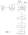
- the light sensor comprises a photoelectric transducer 10, typically in the form of a phototransistor.
- the level (or average level) of the output signal from the transducer 10 will be significant of the level of incident light, whatever may be the source of the light, and the output signal is applied to an analogue-to-digital converter 11 which functions to sample and digitise the transducer output signal under the control of a following microprocessor 12.
- the output from the analogue-to-digital converter 11 is fed to the microprocessor 12 and a determination is made as to the average value of the difference between quantised high and low levels of the transducer output signal.
- This provides a periodic measure of the level of light falling incident on the transducer 10 and is compared with a reference value for the purpose of producing a HIGH light indication or a LOW light indication.
- a LOW light indication is used to generate a signal which is applied to a relay 13, by way of a driver stage 14, to effect energising of the relay and consequential switching of artificial lighting 15.
- the microprocessor 12 Having energised the lighting 15 as a consequence of the detection of a LOW light condition, the microprocessor 12 provides a time-out function for the purpose of de-energising the relay 13 and switching-off the lighting during the period of the LOW light condition and prior to an event that establishes a HIGH light condition.
- the microprocessor incorporates an integral timing device or network which is indicated diagrammatically as being contained within block 16 in the microprocessor.
- the timing device 16 includes a 24-hour clock counter which normally would be initiated during installation of the complete system and into which a time-out code might be inserted at the same time.
- the present invention provides effectively for re-establishment of the original condition by synchronising the initiation time T 1 with an event time T 3 , when detecting a LOW light (e.g., sunset) condition, and resetting the T 1 -to-T 3 relationship when the LOW light condition occurs next following loss and re-establishment of power.
- a LOW light e.g., sunset
- the re-establishment of this relationship will involve a slight time shift, due to the daily difference in sunset time, but it is thought that the shift will be accommodated by users of the system.
- the device may be programmed to compensate for sunset time shifts during successive 24-hour periods.
- an input (which comprises a processed form of the output from the analogue-to-digital converter 11) is applied to the processing/timing stage in the microprocessor 12 at periodic intervals, typically once per minute but in any case at intervals which are short relative to the time interval t 1 . If the input tests HIGH a ONCE THROUGH function is reset and a relay-off signal is applied to the driver stage 14 for the purpose of de-energising the relay. If the input tests not-HIGH an enquiry is executed to determine if the time-out time T 2 has expired and if it has not a relay-on signal is applied to the driver 14 so that the relay 13 is maintained in an energised state and lighting is maintained. If on making the enquiry it is determined that the time-out time T 2 has expired a relay-off signal is applied to the driver stage 14.
- the ONCE THROUGH program control is set and an enquiry is made as to whether a power failure to the complete system has been recorded. If this enquiry is answered in the negative, the stored sunset time T 3 is updated as the current sunset time, and the further program functions as above described proceed toward applying commands to the relay driver 14,
- the last stored sunset time T 3 is recalled to establish synchronisation between the time T 3 and the initiation time T 1 .
- T 1 is initiated as 00:00 hours (corresponding to 16:00 hours local time) and T 3 is recalled as 02:00 hours (being the last stored sunset time, corresponding to 18:00 hours local time)
- synchronisation is established such that T 1 occurs two hours prior to T 3 (at 16:00 hours local time) and T 2 is then established arithmetically as being 08:00 hours, corresponding to 24:00 hours local time.
- synchronisation may be effected at any time by preserving the daily-modified relationship between T 1 and T 3 , so that the time-out T 2 will be preserved with reference to the original initiation time T 1 .
- the system in accordance with the present invention accommodates seasonal changes and provides for re-establishment of initial conditions without there being a need for a local time clock.
- T 3 shifts between summer and winter i.e., as the time interval t 2 varies
- daily updating of the sunset time i.e. the LOW light condition
- T 3 will enable T 1 to be recalled with reasonable accuracy, (following re-establishment of power) with reference to the next occurring low light input signal to the timing device at any time during the course of a year.
Landscapes
- Circuit Arrangement For Electric Light Sources In General (AREA)
- Electric Clocks (AREA)
- Photometry And Measurement Of Optical Pulse Characteristics (AREA)
- Emergency Protection Circuit Devices (AREA)
- Locating Faults (AREA)
Claims (11)
- Elektronische Zeitschalteinrichtung zur Verwendung im Zusammenhang mit einem Lichtpegelsensor (10) und die eine Einrichtung (12, 16) umfasst, die eine Uhrfunktion bereitstellt und die Einrichtung einer Initiierungszeit T1 bereitstellt, wobei die Einrichtung (12, 16) auch eine Eingabe und Speicherung einer Signalerzeugungszeit T2, zu der ein Auszeitsignal erzeugt wird, wobei T2=T1+t1 ist und t1 ein vorgegebenes Zeitintervall ist, und ein Erzeugen des Auszeitsignals beim Ablauf des vorgegebenen Zeitintervalls t1 nach der Initiierungszeit T1 in sukzessiven 24-Stunden-Perioden bereitstellt; dadurch gekennzeichnet, dass die Einrichtung (11, 12) zum Eingeben und Speichern einer Ereigniszeit T3 einmal während jeder 24-Stunden-Periode im Ansprechen darauf, dass ein vorgegebener Lichtpegel durch den Lichtpegelsensor (10) erfasst wird, und zum Bewirken einer Synchronisation der Initiierungszeit T1 in bezug auf die zuletzt eingegebene Ereigniszeit T3 auf eine Erfassung des vorgegebenen Lichtpegels hin vorgesehen ist.
- Zeitschalteinrichtung nach Anspruch 1, ferner dadurch gekennzeichnet, dass die Einrichtung (12, 16) zum Ausführen der verschiedenen Funktionen innerhalb eines Mikroprozessors verkörpert ist.
- Zeitschalteinrichtung nach Anspruch 2, ferner dadurch gekennzeichnet, dass die Einrichtung mit dem Lichtpegelsensor (10) integriert ist und der Lichtpegelsensor einen fotoelektrischen Wandler beinhaltet.
- Zeitschalteinrichtung nach Anspruch 3, ferner dadurch gekennzeichnet, dass ein Ausgang von dem Lichtpegelsensor in einem A-D-Wandler (10) digitalisiert und von dem Mikroprozessor (12, 16) bei periodischen Intervallen, die relativ zu dem vorgegebenen Zeitintervall t1 kurz sind, verarbeitet wird.
- Zeitschalteinrichtung nach einem der Ansprüche 2 bis 4, ferner dadurch gekennzeichnet, dass der Ausgang von dem Mikroprozessor (12, 16) mit Hilfe einer Treiberschaltung (14) an ein Relais (13) angelegt wird, das angeordnet ist, um Energie an eine Beleuchtungsschaltung (15) zu schalten.
- Verfahren zum Erzeugen eines Auszeitsignals zu einer gewählten Signalerzeugungszeit T2 und das die folgenden Schritte umfasst: Einrichten einer Uhrfunktion und einer Initiierungszeit T1, Eingeben und Speichern der Signalerzeugungszeit T2, zu der das Auszeitsignal erzeugt werden soll, wobei T2=T1+t1 ist und t1 ein vorgegebenes Zeitintervall ist, und Erzeugen des Auszeitsignals beim Ablauf des vorgegebenen Zeitintervalls t1 nach der Initiierungszeit T1 in sukzessiven 24-Stunden-Perioden; dadurch gekennzeichnet, dass das Verfahren ferner umfasst die Schritte zum Eingeben und Speichern einer Ereigniszeit T3 einmal während jeder 24-Stunden-Periode im Ansprechen auf die Erfassung eines vorgegebenen Lichtpegels durch einen Lichtpegelsensor, und Verwenden der zuletzt eingegebenen Zeit T3, um die Initiierungszeit T1 in bezug auf die Ereigniszeit T3 auf eine periodische Erfassung des vorgegebenen Lichtpegels hin zu synchronisieren
- Verfahren nach Anspruch 6, ferner dadurch gekennzeichnet, dass eine Synchronisation der Initiierungszeit T1 in bezug auf die Ereigniszeit T3 auf eine Erfassung des vorgegebenen Lichtpegels hin nach einem Ausfall und einer nachfolgenden Wiederherstellung von Energie an einer Zeitschalteinrichtung, die den Lichtpegelsensor beinhaltet, bewirkt wird.
- Verfahren nach Anspruch 6 oder Anspruch 7, ferner dadurch gekennzeichnet, dass die periodisch auftretende Ereigniszeit T3 auf eine Erfassung einer NIEDRIG-Lichtbedingung eingegeben und gespeichert wird.
- Verfahren nach Anspruch 8, ferner dadurch gekennzeichnet, dass die periodisch auftretende Ereigniszeit T3 auf die Erfassung einer NIEDRIG-Lichtbedingung, die als Folge eines Sonnenuntergangs festgestellt wird, eingegeben und gespeichert wird.
- Verfahren nach irgendeinem der Ansprüche 6 bis 9, ferner dadurch gekennzeichnet, dass die Ereigniszeit T3 als T3=T1+t2 festgestellt wird und wobei t2 ein Zeitintervall ist, das kürzer als das Zeitintervall t1 ist.
- Verfahren nach irgendeinem der Ansprüche 6 bis 10, ferner dadurch gekennzeichnet, dass zu periodischen Testintervallen ein Test nach der Existenz des vorgegebenen Lichtpegels durchgeführt wird und wobei jede Testintervallperiode zu dem vorgegebenen Zeitintervall t1 relativ kurz ist.
Applications Claiming Priority (5)
| Application Number | Priority Date | Filing Date | Title |
|---|---|---|---|
| AUPN2114/95 | 1995-03-31 | ||
| AUPN2114A AUPN211495A0 (en) | 1995-03-31 | 1995-03-31 | Synchronised timing device |
| AUPN211495 | 1995-03-31 | ||
| US08/728,840 US5825019A (en) | 1995-03-31 | 1996-10-10 | Timing device capable of synchronizing initiation time |
| CA002188977A CA2188977C (en) | 1995-03-31 | 1996-10-28 | Synchronised timing device |
Publications (3)
| Publication Number | Publication Date |
|---|---|
| EP0738100A2 EP0738100A2 (de) | 1996-10-16 |
| EP0738100A3 EP0738100A3 (de) | 1996-10-30 |
| EP0738100B1 true EP0738100B1 (de) | 2001-12-12 |
Family
ID=27157844
Family Applications (1)
| Application Number | Title | Priority Date | Filing Date |
|---|---|---|---|
| EP96302321A Expired - Lifetime EP0738100B1 (de) | 1995-03-31 | 1996-04-01 | Synchronisierter Zeitschalter |
Country Status (5)
| Country | Link |
|---|---|
| US (1) | US5825019A (de) |
| EP (1) | EP0738100B1 (de) |
| AU (1) | AUPN211495A0 (de) |
| CA (1) | CA2188977C (de) |
| NZ (1) | NZ286278A (de) |
Families Citing this family (9)
| Publication number | Priority date | Publication date | Assignee | Title |
|---|---|---|---|---|
| US6121875A (en) * | 1996-02-08 | 2000-09-19 | Inform 2000 | Monitoring and alerting system for buildings |
| DE19808902C1 (de) * | 1998-03-03 | 1999-05-06 | Innotronic Vertriebs Gmbh | Verfahren und Vorrichtung zum Beleuchten eines tageslichtzugänglichen Raumes |
| FR2805355B1 (fr) * | 2000-02-22 | 2002-05-03 | L2G | Dispositif de commande perfectionnee d'une alimentation electrique, notamment pour candelabres d'eclairage public |
| KR100455961B1 (ko) * | 2001-11-06 | 2004-11-10 | 하가전자 주식회사 | 조명등용 전자식 벽 스위치기의 방범기능 수행방법 및 그기능이 있는 스위치기 |
| FR2847760B1 (fr) * | 2002-11-27 | 2006-12-22 | App Et Bobinage Electr Du Limo | Procede et dispositif de commande en eclairage reduit |
| FR2877476A1 (fr) * | 2004-11-03 | 2006-05-05 | Etude Concept Electronique Sa | Procede et dispositif de reception de commande |
| US7339471B1 (en) * | 2004-12-30 | 2008-03-04 | Cordelia Lighting, Inc. | Nighttime-controlled lighting system |
| TWI487430B (zh) * | 2008-01-15 | 2015-06-01 | 皇家飛利浦電子股份有限公司 | 光源 |
| EP2578060A1 (de) | 2010-05-28 | 2013-04-10 | Honeywell International Inc. | Synchronisierung von lichtquellen |
Family Cites Families (3)
| Publication number | Priority date | Publication date | Assignee | Title |
|---|---|---|---|---|
| US4198563A (en) * | 1978-07-24 | 1980-04-15 | Elssner Egon H | Photodetector timer network |
| US4237377A (en) * | 1979-05-23 | 1980-12-02 | Sansum Victor H | Photoelectric lamp control with sun-synchronized timer |
| IL87813A (en) * | 1987-09-21 | 1993-08-18 | Udden | Measuring light intensity variations |
-
1995
- 1995-03-31 AU AUPN2114A patent/AUPN211495A0/en not_active Abandoned
-
1996
- 1996-03-29 NZ NZ286278A patent/NZ286278A/en unknown
- 1996-04-01 EP EP96302321A patent/EP0738100B1/de not_active Expired - Lifetime
- 1996-10-10 US US08/728,840 patent/US5825019A/en not_active Expired - Fee Related
- 1996-10-28 CA CA002188977A patent/CA2188977C/en not_active Expired - Fee Related
Also Published As
| Publication number | Publication date |
|---|---|
| CA2188977C (en) | 2004-08-31 |
| EP0738100A3 (de) | 1996-10-30 |
| EP0738100A2 (de) | 1996-10-16 |
| US5825019A (en) | 1998-10-20 |
| CA2188977A1 (en) | 1998-04-28 |
| NZ286278A (en) | 1997-06-24 |
| AUPN211495A0 (en) | 1995-04-27 |
Similar Documents
| Publication | Publication Date | Title |
|---|---|---|
| EP0738100B1 (de) | Synchronisierter Zeitschalter | |
| CA1225431A (en) | Excess light turn-off circuit | |
| US4733081A (en) | Method and apparatus for sensing a human body | |
| JP2015503192A (ja) | 街灯自動点滅制御装置およびその方法 | |
| US5990628A (en) | Light level sensor for detecting the level of incident light and discriminating between natural and artificial light | |
| EP0669604A1 (de) | Schaltung zum Infrarotnachweis und Schaltkreis | |
| US5051936A (en) | Microprocessor-based controller with synchronous reset | |
| EP0879442B1 (de) | Verfahren zur steuerung eines schalters und eines lichtaktivierten schalters | |
| AU715500B2 (en) | Synchronised timing device | |
| US4213062A (en) | Method and apparatus for prescribing a time of day | |
| US5140132A (en) | Method of and apparatus for controlling fixing device in electrophotographic recording system | |
| JPS555417A (en) | Air-fuel ratio controller | |
| JPH0696866A (ja) | 照明制御システム | |
| US6671157B1 (en) | Method for effecting an electronic drive control | |
| JPH09261863A (ja) | 電力デマンド制御装置 | |
| JP3890645B2 (ja) | 照明装置 | |
| JPH06168786A (ja) | 照明制御システム | |
| EP0936577B1 (de) | System zur Kontrolle der Funktionstüchtigkeit einer Vorrichtung durch Vergleich mit dem Funktionieren einer anderen Vorrichtung | |
| AU701853B2 (en) | Light sensor | |
| JP2002203688A (ja) | 照明制御装置 | |
| GB2205459A (en) | Electric current monitoring | |
| SU1317563A2 (ru) | Устройство дл автоматического регулировани электрической нагрузки | |
| RU2128410C1 (ru) | Способ управления лампами накаливания | |
| SU1224503A1 (ru) | Автоматическа система регулировани температуры пара котлоагрегата | |
| FR2710205A1 (fr) | Procédé de distribution contrôlée d'énergie et dispositif pour la mise en Óoeuvre du procédé. |
Legal Events
| Date | Code | Title | Description |
|---|---|---|---|
| PUAI | Public reference made under article 153(3) epc to a published international application that has entered the european phase |
Free format text: ORIGINAL CODE: 0009012 |
|
| PUAL | Search report despatched |
Free format text: ORIGINAL CODE: 0009013 |
|
| AK | Designated contracting states |
Kind code of ref document: A2 Designated state(s): BE DE ES FR GB IT NL SE |
|
| AK | Designated contracting states |
Kind code of ref document: A3 Designated state(s): BE DE ES FR GB IT NL SE |
|
| 17P | Request for examination filed |
Effective date: 19970404 |
|
| 17Q | First examination report despatched |
Effective date: 19990215 |
|
| GRAG | Despatch of communication of intention to grant |
Free format text: ORIGINAL CODE: EPIDOS AGRA |
|
| GRAG | Despatch of communication of intention to grant |
Free format text: ORIGINAL CODE: EPIDOS AGRA |
|
| GRAH | Despatch of communication of intention to grant a patent |
Free format text: ORIGINAL CODE: EPIDOS IGRA |
|
| GRAH | Despatch of communication of intention to grant a patent |
Free format text: ORIGINAL CODE: EPIDOS IGRA |
|
| GRAA | (expected) grant |
Free format text: ORIGINAL CODE: 0009210 |
|
| AK | Designated contracting states |
Kind code of ref document: B1 Designated state(s): BE DE ES FR GB IT NL SE |
|
| PG25 | Lapsed in a contracting state [announced via postgrant information from national office to epo] |
Ref country code: NL Free format text: LAPSE BECAUSE OF FAILURE TO SUBMIT A TRANSLATION OF THE DESCRIPTION OR TO PAY THE FEE WITHIN THE PRESCRIBED TIME-LIMIT Effective date: 20011212 Ref country code: IT Free format text: LAPSE BECAUSE OF FAILURE TO SUBMIT A TRANSLATION OF THE DESCRIPTION OR TO PAY THE FEE WITHIN THE PRESCRIBED TIME-LIMIT;WARNING: LAPSES OF ITALIAN PATENTS WITH EFFECTIVE DATE BEFORE 2007 MAY HAVE OCCURRED AT ANY TIME BEFORE 2007. THE CORRECT EFFECTIVE DATE MAY BE DIFFERENT FROM THE ONE RECORDED. Effective date: 20011212 Ref country code: FR Free format text: LAPSE BECAUSE OF FAILURE TO SUBMIT A TRANSLATION OF THE DESCRIPTION OR TO PAY THE FEE WITHIN THE PRESCRIBED TIME-LIMIT Effective date: 20011212 Ref country code: BE Free format text: LAPSE BECAUSE OF FAILURE TO SUBMIT A TRANSLATION OF THE DESCRIPTION OR TO PAY THE FEE WITHIN THE PRESCRIBED TIME-LIMIT Effective date: 20011212 |
|
| REG | Reference to a national code |
Ref country code: GB Ref legal event code: IF02 |
|
| REF | Corresponds to: |
Ref document number: 69617790 Country of ref document: DE Date of ref document: 20020124 |
|
| PG25 | Lapsed in a contracting state [announced via postgrant information from national office to epo] |
Ref country code: SE Free format text: LAPSE BECAUSE OF FAILURE TO SUBMIT A TRANSLATION OF THE DESCRIPTION OR TO PAY THE FEE WITHIN THE PRESCRIBED TIME-LIMIT Effective date: 20020312 |
|
| PG25 | Lapsed in a contracting state [announced via postgrant information from national office to epo] |
Ref country code: DE Free format text: LAPSE BECAUSE OF FAILURE TO SUBMIT A TRANSLATION OF THE DESCRIPTION OR TO PAY THE FEE WITHIN THE PRESCRIBED TIME-LIMIT Effective date: 20020313 |
|
| NLV1 | Nl: lapsed or annulled due to failure to fulfill the requirements of art. 29p and 29m of the patents act | ||
| PG25 | Lapsed in a contracting state [announced via postgrant information from national office to epo] |
Ref country code: ES Free format text: LAPSE BECAUSE OF FAILURE TO SUBMIT A TRANSLATION OF THE DESCRIPTION OR TO PAY THE FEE WITHIN THE PRESCRIBED TIME-LIMIT Effective date: 20020627 |
|
| EN | Fr: translation not filed | ||
| PLBE | No opposition filed within time limit |
Free format text: ORIGINAL CODE: 0009261 |
|
| STAA | Information on the status of an ep patent application or granted ep patent |
Free format text: STATUS: NO OPPOSITION FILED WITHIN TIME LIMIT |
|
| 26N | No opposition filed | ||
| NLV1 | Nl: lapsed or annulled due to failure to fulfill the requirements of art. 29p and 29m of the patents act | ||
| PGFP | Annual fee paid to national office [announced via postgrant information from national office to epo] |
Ref country code: GB Payment date: 20050330 Year of fee payment: 10 |
|
| PG25 | Lapsed in a contracting state [announced via postgrant information from national office to epo] |
Ref country code: GB Free format text: LAPSE BECAUSE OF NON-PAYMENT OF DUE FEES Effective date: 20060401 |
|
| GBPC | Gb: european patent ceased through non-payment of renewal fee |
Effective date: 20060401 |