EP0738100A2 - Synchronisierter Zeitschalter - Google Patents
Synchronisierter Zeitschalter Download PDFInfo
- Publication number
- EP0738100A2 EP0738100A2 EP96302321A EP96302321A EP0738100A2 EP 0738100 A2 EP0738100 A2 EP 0738100A2 EP 96302321 A EP96302321 A EP 96302321A EP 96302321 A EP96302321 A EP 96302321A EP 0738100 A2 EP0738100 A2 EP 0738100A2
- Authority
- EP
- European Patent Office
- Prior art keywords
- time
- light level
- predetermined
- further characterised
- timing device
- Prior art date
- Legal status (The legal status is an assumption and is not a legal conclusion. Google has not performed a legal analysis and makes no representation as to the accuracy of the status listed.)
- Granted
Links
Images
Classifications
-
- H—ELECTRICITY
- H05—ELECTRIC TECHNIQUES NOT OTHERWISE PROVIDED FOR
- H05B—ELECTRIC HEATING; ELECTRIC LIGHT SOURCES NOT OTHERWISE PROVIDED FOR; CIRCUIT ARRANGEMENTS FOR ELECTRIC LIGHT SOURCES, IN GENERAL
- H05B47/00—Circuit arrangements for operating light sources in general, i.e. where the type of light source is not relevant
- H05B47/10—Controlling the light source
- H05B47/105—Controlling the light source in response to determined parameters
- H05B47/11—Controlling the light source in response to determined parameters by determining the brightness or colour temperature of ambient light
-
- H—ELECTRICITY
- H05—ELECTRIC TECHNIQUES NOT OTHERWISE PROVIDED FOR
- H05B—ELECTRIC HEATING; ELECTRIC LIGHT SOURCES NOT OTHERWISE PROVIDED FOR; CIRCUIT ARRANGEMENTS FOR ELECTRIC LIGHT SOURCES, IN GENERAL
- H05B47/00—Circuit arrangements for operating light sources in general, i.e. where the type of light source is not relevant
- H05B47/10—Controlling the light source
- H05B47/16—Controlling the light source by timing means
-
- Y—GENERAL TAGGING OF NEW TECHNOLOGICAL DEVELOPMENTS; GENERAL TAGGING OF CROSS-SECTIONAL TECHNOLOGIES SPANNING OVER SEVERAL SECTIONS OF THE IPC; TECHNICAL SUBJECTS COVERED BY FORMER USPC CROSS-REFERENCE ART COLLECTIONS [XRACs] AND DIGESTS
- Y02—TECHNOLOGIES OR APPLICATIONS FOR MITIGATION OR ADAPTATION AGAINST CLIMATE CHANGE
- Y02B—CLIMATE CHANGE MITIGATION TECHNOLOGIES RELATED TO BUILDINGS, e.g. HOUSING, HOUSE APPLIANCES OR RELATED END-USER APPLICATIONS
- Y02B20/00—Energy efficient lighting technologies, e.g. halogen lamps or gas discharge lamps
- Y02B20/40—Control techniques providing energy savings, e.g. smart controller or presence detection
Definitions
- This invention relates to a timing device which is associated with a photoelectric transducer and which is arranged to be synchronised with reference to a predetermined lighting condition that is sensed by the transducer.
- Photoelectric transducers are conventionally employed in light level sensors which are used for detecting the level of ambient light and for controlling the switching of electrical circuits with changes in ambient light levels. In some applications it is required that switch-on should occur when the ambient light falls below a predetermined level (for example at sunset) and that switch-off should occur at a time which precedes the following sunrise. This requirement is conventionally met by locating a timer in circuit with the light level sensor and by setting the timer to effect switch-off at a particular local time. However, a timer requires sustained power or battery back-up in order that it might function in a predictable manner and, thus, provide for consistent switch-off operations. Alternatively, vigilance must be maintained and the timer must promptly be reset following power failures, again in the interest of avoiding erratic switch-off timing.
- the present invention is directed to a timing device which is synchronised by reference to a predetermined lighting condition and which avoids at least some of the problems associated with conventional light level sensor-timer devices.
- the present invention provides a timing device for use in conjunction with a light level sensor and which comprises:
- the invention may alternatively be defined in terms of a method of generating the time-out signal at a selected signal generating time T 2 and which comprises the steps of:
- the timing device is arranged to be "self-adjusting".
- the device will continue to provide a time-out signal at the originally selected time T 2 , provided only that the predetermined light level is detected at event time T 3 to act as the trigger for synchronisation of the device after power is restored.
- Appropriate controls such as operating condition checks and response delays may be incorporated in the device in order that discrimination might be provided against transient false indications of the predetermined light condition.
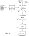
- the light sensor comprises a photoelectric transducer 10, typically in the form of a phototransistor.
- the level (or average level) of the output signal from the transducer 10 will be significant of the level of incident light, whatever may be the source of the light, and the output signal is applied to an analogue-to-digital converter 11 which functions to sample and digitise the transducer output signal under the control of a following microprocessor 12.
- the output from the analogue-to-digital converter 11 is fed to the microprocessor 12 and a determination is made as to the average value of the difference between quantised high and low levels of the transducer output signal.
- This provides a periodic measure of the level of light falling incident on the transducer 10 and is compared with a reference value for the purpose of producing a HIGH light indication or a LOW light indication.
- a LOW light indication is used to generate a signal which is applied to a relay 13, by way of a driver stage 14, to effect energising of the relay and consequential switching of artificial lighting 15.
- the microprocessor 12 Having energised the lighting 15 as a consequence of the detection of a LOW light condition, the microprocessor 12 provides a time-out function for the purpose of de-energising the relay 13 and switching-off the lighting during the period of the LOW light condition and prior to an event that establishes a HIGH light condition.
- the microprocessor incorporates an integral timing device or network which is indicated diagrammatically as being contained within block 16 in the microprocessor.
- the timing device 16 includes a 24-hour clock counter which normally would be initiated during installation of the complete system and into which a time-out code might be inserted at the same time.
- the present invention provides effectively for re-establishment of the original condition by synchronising the initiation time T 1 with an event time T 3 , when detecting a LOW light (e.g., sunset) condition, and resetting the T 1 -to-T 3 relationship when the LOW light condition occurs next following loss and re-establishment of power.
- a LOW light e.g., sunset
- the re-establishment of this relationship will involve a slight time shift, due to the daily difference in sunset time, but it is thought that the shift will be accommodated by users of the system.
- the device may be programmed to compensate for sunset time shifts during successive 24-hour periods.
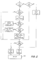
- an input (which comprises a processed form of the output from the analogue-to-digital converter 11) is applied to the processing/timing stage in the microprocessor 12 at periodic intervals, typically once per minute but in any case at intervals which are short relative to the time interval t 1 . If the input tests HIGH a ONCE THROUGH function is reset and a relay-off signal is applied to the driver stage 14 for the purpose of de-energising the relay. If the input tests not-HIGH an enquiry is executed to determine if the time-out time T 2 has expired and if it has not a relay-on signal is applied to the driver 14 so that the relay 13 is maintained in an energised state and lighting is maintained. If on making the enquiry it is determined that the time-out time T 2 has expired a relay-off signal is applied to the driver stage 14.
- the ONCE THROUGH program control is set and an enquiry is made as to whether a power failure to the complete system has been recorded. If this enquiry is answered in the negative, the stored sunset time T 3 is updated as the current sunset time, and the further program functions as above described proceed toward applying commands to the relay driver 14,
- the last stored sunset time T 3 is recalled to establish synchronisation between the time T 3 and the initiation time T 1 .
- T 1 is initiated as 00:00 hours (corresponding to 16:00 hours local time) and T 3 is recalled as 02:00 hours (being the last stored sunset time, corresponding to 18:00 hours local time)
- synchronisation is established such that T 1 occurs two hours prior to T 3 (at 16:00 hours local time) and T 2 is then established arithmetically as being 08:00 hours, corresponding to 24:00 hours local time.
- synchronisation may be effected at any time by preserving the daily-modified relationship between T 1 and T 3 , so that the time-out T 2 will be preserved with reference to the original initiation time T 1 .
- the system in accordance with the present invention accommodates seasonal changes and provides for re-establishment of initial conditions without there being a need for a local time clock.
- T 3 shifts between summer and winter i.e., as the time interval t 2 varies
- daily updating of the sunset time i.e. the LOW light condition
- T 3 will enable T 1 to be recalled with reasonable accuracy, (following re-establishment of power) with reference to the next occurring low light input signal to the timing device at any time during the course of a year.
Landscapes
- Circuit Arrangement For Electric Light Sources In General (AREA)
- Electric Clocks (AREA)
- Photometry And Measurement Of Optical Pulse Characteristics (AREA)
- Emergency Protection Circuit Devices (AREA)
- Locating Faults (AREA)
Applications Claiming Priority (5)
| Application Number | Priority Date | Filing Date | Title |
|---|---|---|---|
| AUPN2114/95 | 1995-03-31 | ||
| AUPN2114A AUPN211495A0 (en) | 1995-03-31 | 1995-03-31 | Synchronised timing device |
| AUPN211495 | 1995-03-31 | ||
| US08/728,840 US5825019A (en) | 1995-03-31 | 1996-10-10 | Timing device capable of synchronizing initiation time |
| CA002188977A CA2188977C (en) | 1995-03-31 | 1996-10-28 | Synchronised timing device |
Publications (3)
| Publication Number | Publication Date |
|---|---|
| EP0738100A2 true EP0738100A2 (de) | 1996-10-16 |
| EP0738100A3 EP0738100A3 (de) | 1996-10-30 |
| EP0738100B1 EP0738100B1 (de) | 2001-12-12 |
Family
ID=27157844
Family Applications (1)
| Application Number | Title | Priority Date | Filing Date |
|---|---|---|---|
| EP96302321A Expired - Lifetime EP0738100B1 (de) | 1995-03-31 | 1996-04-01 | Synchronisierter Zeitschalter |
Country Status (5)
| Country | Link |
|---|---|
| US (1) | US5825019A (de) |
| EP (1) | EP0738100B1 (de) |
| AU (1) | AUPN211495A0 (de) |
| CA (1) | CA2188977C (de) |
| NZ (1) | NZ286278A (de) |
Cited By (7)
| Publication number | Priority date | Publication date | Assignee | Title |
|---|---|---|---|---|
| DE19808902C1 (de) * | 1998-03-03 | 1999-05-06 | Innotronic Vertriebs Gmbh | Verfahren und Vorrichtung zum Beleuchten eines tageslichtzugänglichen Raumes |
| FR2805355A1 (fr) * | 2000-02-22 | 2001-08-24 | L2G | Dispositif de commande perfectionnee d'une alimentation electrique, notamment pour candelabres d'eclairage public |
| FR2847760A1 (fr) * | 2002-11-27 | 2004-05-28 | App Et Bobinage Electr Du Limo | Procede et dispositif de commande en eclairage reduit |
| EP1446986A4 (de) * | 2001-11-06 | 2004-12-01 | Haga Electronics Co Ltd | Elektronischer schalter für eine lampe mit sicherheitsfunktion |
| FR2877476A1 (fr) * | 2004-11-03 | 2006-05-05 | Etude Concept Electronique Sa | Procede et dispositif de reception de commande |
| EP2236009A1 (de) * | 2008-01-15 | 2010-10-06 | Koninklijke Philips Electronics N.V. | Lichtquelle |
| WO2011149473A1 (en) | 2010-05-28 | 2011-12-01 | Honeywell International Inc. | Synchronization of light sources |
Families Citing this family (2)
| Publication number | Priority date | Publication date | Assignee | Title |
|---|---|---|---|---|
| US6121875A (en) * | 1996-02-08 | 2000-09-19 | Inform 2000 | Monitoring and alerting system for buildings |
| US7339471B1 (en) * | 2004-12-30 | 2008-03-04 | Cordelia Lighting, Inc. | Nighttime-controlled lighting system |
Family Cites Families (3)
| Publication number | Priority date | Publication date | Assignee | Title |
|---|---|---|---|---|
| US4198563A (en) * | 1978-07-24 | 1980-04-15 | Elssner Egon H | Photodetector timer network |
| US4237377A (en) * | 1979-05-23 | 1980-12-02 | Sansum Victor H | Photoelectric lamp control with sun-synchronized timer |
| IL87813A (en) * | 1987-09-21 | 1993-08-18 | Udden | Measuring light intensity variations |
-
1995
- 1995-03-31 AU AUPN2114A patent/AUPN211495A0/en not_active Abandoned
-
1996
- 1996-03-29 NZ NZ286278A patent/NZ286278A/en unknown
- 1996-04-01 EP EP96302321A patent/EP0738100B1/de not_active Expired - Lifetime
- 1996-10-10 US US08/728,840 patent/US5825019A/en not_active Expired - Fee Related
- 1996-10-28 CA CA002188977A patent/CA2188977C/en not_active Expired - Fee Related
Non-Patent Citations (1)
| Title |
|---|
| None |
Cited By (7)
| Publication number | Priority date | Publication date | Assignee | Title |
|---|---|---|---|---|
| DE19808902C1 (de) * | 1998-03-03 | 1999-05-06 | Innotronic Vertriebs Gmbh | Verfahren und Vorrichtung zum Beleuchten eines tageslichtzugänglichen Raumes |
| FR2805355A1 (fr) * | 2000-02-22 | 2001-08-24 | L2G | Dispositif de commande perfectionnee d'une alimentation electrique, notamment pour candelabres d'eclairage public |
| EP1446986A4 (de) * | 2001-11-06 | 2004-12-01 | Haga Electronics Co Ltd | Elektronischer schalter für eine lampe mit sicherheitsfunktion |
| FR2847760A1 (fr) * | 2002-11-27 | 2004-05-28 | App Et Bobinage Electr Du Limo | Procede et dispositif de commande en eclairage reduit |
| FR2877476A1 (fr) * | 2004-11-03 | 2006-05-05 | Etude Concept Electronique Sa | Procede et dispositif de reception de commande |
| EP2236009A1 (de) * | 2008-01-15 | 2010-10-06 | Koninklijke Philips Electronics N.V. | Lichtquelle |
| WO2011149473A1 (en) | 2010-05-28 | 2011-12-01 | Honeywell International Inc. | Synchronization of light sources |
Also Published As
| Publication number | Publication date |
|---|---|
| CA2188977C (en) | 2004-08-31 |
| EP0738100A3 (de) | 1996-10-30 |
| US5825019A (en) | 1998-10-20 |
| CA2188977A1 (en) | 1998-04-28 |
| NZ286278A (en) | 1997-06-24 |
| AUPN211495A0 (en) | 1995-04-27 |
| EP0738100B1 (de) | 2001-12-12 |
Similar Documents
| Publication | Publication Date | Title |
|---|---|---|
| EP0738100A2 (de) | Synchronisierter Zeitschalter | |
| US4733081A (en) | Method and apparatus for sensing a human body | |
| AU715500B2 (en) | Synchronised timing device | |
| EP0718609A1 (de) | Lichtsensor | |
| EP0879442B1 (de) | Verfahren zur steuerung eines schalters und eines lichtaktivierten schalters | |
| US4213062A (en) | Method and apparatus for prescribing a time of day | |
| EP0099545A2 (de) | Einrichtung zur Bestimmung der Betriebsbereitschaft einer Sauerstoff-Sonde | |
| EP0599568A2 (de) | Zeitmessvorrichtung | |
| US4151472A (en) | Selective calling circuit employing controlled power supply therefor | |
| CA2236407A1 (en) | Method and apparatus for performing automatic synchronization failure detection in an atm network | |
| US5140132A (en) | Method of and apparatus for controlling fixing device in electrophotographic recording system | |
| US6528971B2 (en) | Indicating method of battery life and electronic device | |
| JPS5554403A (en) | Zero adjuster | |
| JPH04143802A (ja) | 人工衛星追跡管制設備シミュレータ | |
| JPH0451793B2 (de) | ||
| JPS6486080A (en) | Method and apparatus for diagnosing abnormality of current detector | |
| JPH0231404B2 (de) | ||
| SU1415464A1 (ru) | Передающа телевизионна камера | |
| SU1250987A1 (ru) | Устройство дл контрол амплитудно-частотных характеристик | |
| JPH0421181Y2 (de) | ||
| JPS6474896A (en) | Key telephone system | |
| SU1686390A1 (ru) | Способ измерени времени разгона электродвигател | |
| SU1224503A1 (ru) | Автоматическа система регулировани температуры пара котлоагрегата | |
| SU1418885A1 (ru) | Способ автоматического аварийного управлени возбуждением синхронного генератора | |
| JPS5932649A (ja) | 内燃機関の電子制御装置のリセツト方法 |
Legal Events
| Date | Code | Title | Description |
|---|---|---|---|
| PUAI | Public reference made under article 153(3) epc to a published international application that has entered the european phase |
Free format text: ORIGINAL CODE: 0009012 |
|
| PUAL | Search report despatched |
Free format text: ORIGINAL CODE: 0009013 |
|
| AK | Designated contracting states |
Kind code of ref document: A2 Designated state(s): BE DE ES FR GB IT NL SE |
|
| AK | Designated contracting states |
Kind code of ref document: A3 Designated state(s): BE DE ES FR GB IT NL SE |
|
| 17P | Request for examination filed |
Effective date: 19970404 |
|
| 17Q | First examination report despatched |
Effective date: 19990215 |
|
| GRAG | Despatch of communication of intention to grant |
Free format text: ORIGINAL CODE: EPIDOS AGRA |
|
| GRAG | Despatch of communication of intention to grant |
Free format text: ORIGINAL CODE: EPIDOS AGRA |
|
| GRAH | Despatch of communication of intention to grant a patent |
Free format text: ORIGINAL CODE: EPIDOS IGRA |
|
| GRAH | Despatch of communication of intention to grant a patent |
Free format text: ORIGINAL CODE: EPIDOS IGRA |
|
| GRAA | (expected) grant |
Free format text: ORIGINAL CODE: 0009210 |
|
| AK | Designated contracting states |
Kind code of ref document: B1 Designated state(s): BE DE ES FR GB IT NL SE |
|
| PG25 | Lapsed in a contracting state [announced via postgrant information from national office to epo] |
Ref country code: NL Free format text: LAPSE BECAUSE OF FAILURE TO SUBMIT A TRANSLATION OF THE DESCRIPTION OR TO PAY THE FEE WITHIN THE PRESCRIBED TIME-LIMIT Effective date: 20011212 Ref country code: IT Free format text: LAPSE BECAUSE OF FAILURE TO SUBMIT A TRANSLATION OF THE DESCRIPTION OR TO PAY THE FEE WITHIN THE PRESCRIBED TIME-LIMIT;WARNING: LAPSES OF ITALIAN PATENTS WITH EFFECTIVE DATE BEFORE 2007 MAY HAVE OCCURRED AT ANY TIME BEFORE 2007. THE CORRECT EFFECTIVE DATE MAY BE DIFFERENT FROM THE ONE RECORDED. Effective date: 20011212 Ref country code: FR Free format text: LAPSE BECAUSE OF FAILURE TO SUBMIT A TRANSLATION OF THE DESCRIPTION OR TO PAY THE FEE WITHIN THE PRESCRIBED TIME-LIMIT Effective date: 20011212 Ref country code: BE Free format text: LAPSE BECAUSE OF FAILURE TO SUBMIT A TRANSLATION OF THE DESCRIPTION OR TO PAY THE FEE WITHIN THE PRESCRIBED TIME-LIMIT Effective date: 20011212 |
|
| REG | Reference to a national code |
Ref country code: GB Ref legal event code: IF02 |
|
| REF | Corresponds to: |
Ref document number: 69617790 Country of ref document: DE Date of ref document: 20020124 |
|
| PG25 | Lapsed in a contracting state [announced via postgrant information from national office to epo] |
Ref country code: SE Free format text: LAPSE BECAUSE OF FAILURE TO SUBMIT A TRANSLATION OF THE DESCRIPTION OR TO PAY THE FEE WITHIN THE PRESCRIBED TIME-LIMIT Effective date: 20020312 |
|
| PG25 | Lapsed in a contracting state [announced via postgrant information from national office to epo] |
Ref country code: DE Free format text: LAPSE BECAUSE OF FAILURE TO SUBMIT A TRANSLATION OF THE DESCRIPTION OR TO PAY THE FEE WITHIN THE PRESCRIBED TIME-LIMIT Effective date: 20020313 |
|
| NLV1 | Nl: lapsed or annulled due to failure to fulfill the requirements of art. 29p and 29m of the patents act | ||
| PG25 | Lapsed in a contracting state [announced via postgrant information from national office to epo] |
Ref country code: ES Free format text: LAPSE BECAUSE OF FAILURE TO SUBMIT A TRANSLATION OF THE DESCRIPTION OR TO PAY THE FEE WITHIN THE PRESCRIBED TIME-LIMIT Effective date: 20020627 |
|
| EN | Fr: translation not filed | ||
| PLBE | No opposition filed within time limit |
Free format text: ORIGINAL CODE: 0009261 |
|
| STAA | Information on the status of an ep patent application or granted ep patent |
Free format text: STATUS: NO OPPOSITION FILED WITHIN TIME LIMIT |
|
| 26N | No opposition filed | ||
| NLV1 | Nl: lapsed or annulled due to failure to fulfill the requirements of art. 29p and 29m of the patents act | ||
| PGFP | Annual fee paid to national office [announced via postgrant information from national office to epo] |
Ref country code: GB Payment date: 20050330 Year of fee payment: 10 |
|
| PG25 | Lapsed in a contracting state [announced via postgrant information from national office to epo] |
Ref country code: GB Free format text: LAPSE BECAUSE OF NON-PAYMENT OF DUE FEES Effective date: 20060401 |
|
| GBPC | Gb: european patent ceased through non-payment of renewal fee |
Effective date: 20060401 |