EP0737564A2 - Procédé et dispositif pour couper un produit élastomère stratifié renforcé par des cordes - Google Patents
Procédé et dispositif pour couper un produit élastomère stratifié renforcé par des cordes Download PDFInfo
- Publication number
- EP0737564A2 EP0737564A2 EP95203571A EP95203571A EP0737564A2 EP 0737564 A2 EP0737564 A2 EP 0737564A2 EP 95203571 A EP95203571 A EP 95203571A EP 95203571 A EP95203571 A EP 95203571A EP 0737564 A2 EP0737564 A2 EP 0737564A2
- Authority
- EP
- European Patent Office
- Prior art keywords
- cutting
- ply
- laminate
- cutting element
- cords
- Prior art date
- Legal status (The legal status is an assumption and is not a legal conclusion. Google has not performed a legal analysis and makes no representation as to the accuracy of the status listed.)
- Granted
Links
Images


Classifications
-
- B—PERFORMING OPERATIONS; TRANSPORTING
- B26—HAND CUTTING TOOLS; CUTTING; SEVERING
- B26D—CUTTING; DETAILS COMMON TO MACHINES FOR PERFORATING, PUNCHING, CUTTING-OUT, STAMPING-OUT OR SEVERING
- B26D3/00—Cutting work characterised by the nature of the cut made; Apparatus therefor
- B26D3/003—Cutting work characterised by the nature of the cut made; Apparatus therefor specially adapted for cutting rubber
-
- B—PERFORMING OPERATIONS; TRANSPORTING
- B26—HAND CUTTING TOOLS; CUTTING; SEVERING
- B26D—CUTTING; DETAILS COMMON TO MACHINES FOR PERFORATING, PUNCHING, CUTTING-OUT, STAMPING-OUT OR SEVERING
- B26D1/00—Cutting through work characterised by the nature or movement of the cutting member or particular materials not otherwise provided for; Apparatus or machines therefor; Cutting members therefor
- B26D1/01—Cutting through work characterised by the nature or movement of the cutting member or particular materials not otherwise provided for; Apparatus or machines therefor; Cutting members therefor involving a cutting member which does not travel with the work
- B26D1/04—Cutting through work characterised by the nature or movement of the cutting member or particular materials not otherwise provided for; Apparatus or machines therefor; Cutting members therefor involving a cutting member which does not travel with the work having a linearly-movable cutting member
- B26D1/045—Cutting through work characterised by the nature or movement of the cutting member or particular materials not otherwise provided for; Apparatus or machines therefor; Cutting members therefor involving a cutting member which does not travel with the work having a linearly-movable cutting member for thin material, e.g. for sheets, strips or the like
-
- B—PERFORMING OPERATIONS; TRANSPORTING
- B26—HAND CUTTING TOOLS; CUTTING; SEVERING
- B26D—CUTTING; DETAILS COMMON TO MACHINES FOR PERFORATING, PUNCHING, CUTTING-OUT, STAMPING-OUT OR SEVERING
- B26D1/00—Cutting through work characterised by the nature or movement of the cutting member or particular materials not otherwise provided for; Apparatus or machines therefor; Cutting members therefor
- B26D1/01—Cutting through work characterised by the nature or movement of the cutting member or particular materials not otherwise provided for; Apparatus or machines therefor; Cutting members therefor involving a cutting member which does not travel with the work
- B26D1/04—Cutting through work characterised by the nature or movement of the cutting member or particular materials not otherwise provided for; Apparatus or machines therefor; Cutting members therefor involving a cutting member which does not travel with the work having a linearly-movable cutting member
- B26D1/06—Cutting through work characterised by the nature or movement of the cutting member or particular materials not otherwise provided for; Apparatus or machines therefor; Cutting members therefor involving a cutting member which does not travel with the work having a linearly-movable cutting member wherein the cutting member reciprocates
- B26D1/10—Cutting through work characterised by the nature or movement of the cutting member or particular materials not otherwise provided for; Apparatus or machines therefor; Cutting members therefor involving a cutting member which does not travel with the work having a linearly-movable cutting member wherein the cutting member reciprocates in, or substantially in, a direction parallel to the cutting edge
- B26D1/105—Cutting through work characterised by the nature or movement of the cutting member or particular materials not otherwise provided for; Apparatus or machines therefor; Cutting members therefor involving a cutting member which does not travel with the work having a linearly-movable cutting member wherein the cutting member reciprocates in, or substantially in, a direction parallel to the cutting edge for thin material, e.g. for sheets, strips or the like
-
- B—PERFORMING OPERATIONS; TRANSPORTING
- B26—HAND CUTTING TOOLS; CUTTING; SEVERING
- B26D—CUTTING; DETAILS COMMON TO MACHINES FOR PERFORATING, PUNCHING, CUTTING-OUT, STAMPING-OUT OR SEVERING
- B26D1/00—Cutting through work characterised by the nature or movement of the cutting member or particular materials not otherwise provided for; Apparatus or machines therefor; Cutting members therefor
- B26D1/01—Cutting through work characterised by the nature or movement of the cutting member or particular materials not otherwise provided for; Apparatus or machines therefor; Cutting members therefor involving a cutting member which does not travel with the work
- B26D1/547—Cutting through work characterised by the nature or movement of the cutting member or particular materials not otherwise provided for; Apparatus or machines therefor; Cutting members therefor involving a cutting member which does not travel with the work having a wire-like cutting member
- B26D1/5475—Cutting through work characterised by the nature or movement of the cutting member or particular materials not otherwise provided for; Apparatus or machines therefor; Cutting members therefor involving a cutting member which does not travel with the work having a wire-like cutting member for thin material, e.g. for sheets, strips or the like
-
- B—PERFORMING OPERATIONS; TRANSPORTING
- B26—HAND CUTTING TOOLS; CUTTING; SEVERING
- B26D—CUTTING; DETAILS COMMON TO MACHINES FOR PERFORATING, PUNCHING, CUTTING-OUT, STAMPING-OUT OR SEVERING
- B26D3/00—Cutting work characterised by the nature of the cut made; Apparatus therefor
- B26D3/02—Bevelling
-
- B—PERFORMING OPERATIONS; TRANSPORTING
- B29—WORKING OF PLASTICS; WORKING OF SUBSTANCES IN A PLASTIC STATE IN GENERAL
- B29D—PRODUCING PARTICULAR ARTICLES FROM PLASTICS OR FROM SUBSTANCES IN A PLASTIC STATE
- B29D30/00—Producing pneumatic or solid tyres or parts thereof
-
- B—PERFORMING OPERATIONS; TRANSPORTING
- B29—WORKING OF PLASTICS; WORKING OF SUBSTANCES IN A PLASTIC STATE IN GENERAL
- B29D—PRODUCING PARTICULAR ARTICLES FROM PLASTICS OR FROM SUBSTANCES IN A PLASTIC STATE
- B29D30/00—Producing pneumatic or solid tyres or parts thereof
- B29D30/06—Pneumatic tyres or parts thereof (e.g. produced by casting, moulding, compression moulding, injection moulding, centrifugal casting)
- B29D30/38—Textile inserts, e.g. cord or canvas layers, for tyres; Treatment of inserts prior to building the tyre
- B29D30/46—Cutting textile inserts to required shape
-
- B—PERFORMING OPERATIONS; TRANSPORTING
- B29—WORKING OF PLASTICS; WORKING OF SUBSTANCES IN A PLASTIC STATE IN GENERAL
- B29C—SHAPING OR JOINING OF PLASTICS; SHAPING OF MATERIAL IN A PLASTIC STATE, NOT OTHERWISE PROVIDED FOR; AFTER-TREATMENT OF THE SHAPED PRODUCTS, e.g. REPAIRING
- B29C66/00—General aspects of processes or apparatus for joining preformed parts
- B29C66/01—General aspects dealing with the joint area or with the area to be joined
- B29C66/05—Particular design of joint configurations
- B29C66/10—Particular design of joint configurations particular design of the joint cross-sections
- B29C66/12—Joint cross-sections combining only two joint-segments; Tongue and groove joints; Tenon and mortise joints; Stepped joint cross-sections
- B29C66/128—Stepped joint cross-sections
- B29C66/1286—Stepped joint cross-sections comprising at least one bevelled joint-segment
- B29C66/12861—Stepped joint cross-sections comprising at least one bevelled joint-segment comprising at least two bevelled joint-segments
-
- B—PERFORMING OPERATIONS; TRANSPORTING
- B29—WORKING OF PLASTICS; WORKING OF SUBSTANCES IN A PLASTIC STATE IN GENERAL
- B29C—SHAPING OR JOINING OF PLASTICS; SHAPING OF MATERIAL IN A PLASTIC STATE, NOT OTHERWISE PROVIDED FOR; AFTER-TREATMENT OF THE SHAPED PRODUCTS, e.g. REPAIRING
- B29C66/00—General aspects of processes or apparatus for joining preformed parts
- B29C66/01—General aspects dealing with the joint area or with the area to be joined
- B29C66/05—Particular design of joint configurations
- B29C66/10—Particular design of joint configurations particular design of the joint cross-sections
- B29C66/14—Particular design of joint configurations particular design of the joint cross-sections the joint having the same thickness as the thickness of the parts to be joined
-
- Y—GENERAL TAGGING OF NEW TECHNOLOGICAL DEVELOPMENTS; GENERAL TAGGING OF CROSS-SECTIONAL TECHNOLOGIES SPANNING OVER SEVERAL SECTIONS OF THE IPC; TECHNICAL SUBJECTS COVERED BY FORMER USPC CROSS-REFERENCE ART COLLECTIONS [XRACs] AND DIGESTS
- Y10—TECHNICAL SUBJECTS COVERED BY FORMER USPC
- Y10T—TECHNICAL SUBJECTS COVERED BY FORMER US CLASSIFICATION
- Y10T83/00—Cutting
- Y10T83/04—Processes
- Y10T83/05—With reorientation of tool between cuts
-
- Y—GENERAL TAGGING OF NEW TECHNOLOGICAL DEVELOPMENTS; GENERAL TAGGING OF CROSS-SECTIONAL TECHNOLOGIES SPANNING OVER SEVERAL SECTIONS OF THE IPC; TECHNICAL SUBJECTS COVERED BY FORMER USPC CROSS-REFERENCE ART COLLECTIONS [XRACs] AND DIGESTS
- Y10—TECHNICAL SUBJECTS COVERED BY FORMER USPC
- Y10T—TECHNICAL SUBJECTS COVERED BY FORMER US CLASSIFICATION
- Y10T83/00—Cutting
- Y10T83/04—Processes
- Y10T83/0605—Cut advances across work surface
-
- Y—GENERAL TAGGING OF NEW TECHNOLOGICAL DEVELOPMENTS; GENERAL TAGGING OF CROSS-SECTIONAL TECHNOLOGIES SPANNING OVER SEVERAL SECTIONS OF THE IPC; TECHNICAL SUBJECTS COVERED BY FORMER USPC CROSS-REFERENCE ART COLLECTIONS [XRACs] AND DIGESTS
- Y10—TECHNICAL SUBJECTS COVERED BY FORMER USPC
- Y10T—TECHNICAL SUBJECTS COVERED BY FORMER US CLASSIFICATION
- Y10T83/00—Cutting
- Y10T83/444—Tool engages work during dwell of intermittent workfeed
- Y10T83/4475—Tool has motion additional to cutting stroke during tool cycle
- Y10T83/4478—Tool has additional motion during work dwell
- Y10T83/448—Included in plural cutting cycles
-
- Y—GENERAL TAGGING OF NEW TECHNOLOGICAL DEVELOPMENTS; GENERAL TAGGING OF CROSS-SECTIONAL TECHNOLOGIES SPANNING OVER SEVERAL SECTIONS OF THE IPC; TECHNICAL SUBJECTS COVERED BY FORMER USPC CROSS-REFERENCE ART COLLECTIONS [XRACs] AND DIGESTS
- Y10—TECHNICAL SUBJECTS COVERED BY FORMER USPC
- Y10T—TECHNICAL SUBJECTS COVERED BY FORMER US CLASSIFICATION
- Y10T83/00—Cutting
- Y10T83/687—By tool reciprocable along elongated edge
- Y10T83/705—With means to support tool at opposite ends
-
- Y—GENERAL TAGGING OF NEW TECHNOLOGICAL DEVELOPMENTS; GENERAL TAGGING OF CROSS-SECTIONAL TECHNOLOGIES SPANNING OVER SEVERAL SECTIONS OF THE IPC; TECHNICAL SUBJECTS COVERED BY FORMER USPC CROSS-REFERENCE ART COLLECTIONS [XRACs] AND DIGESTS
- Y10—TECHNICAL SUBJECTS COVERED BY FORMER USPC
- Y10T—TECHNICAL SUBJECTS COVERED BY FORMER US CLASSIFICATION
- Y10T83/00—Cutting
- Y10T83/869—Means to drive or to guide tool
- Y10T83/8773—Bevel or miter cut
-
- Y—GENERAL TAGGING OF NEW TECHNOLOGICAL DEVELOPMENTS; GENERAL TAGGING OF CROSS-SECTIONAL TECHNOLOGIES SPANNING OVER SEVERAL SECTIONS OF THE IPC; TECHNICAL SUBJECTS COVERED BY FORMER USPC CROSS-REFERENCE ART COLLECTIONS [XRACs] AND DIGESTS
- Y10—TECHNICAL SUBJECTS COVERED BY FORMER USPC
- Y10T—TECHNICAL SUBJECTS COVERED BY FORMER US CLASSIFICATION
- Y10T83/00—Cutting
- Y10T83/869—Means to drive or to guide tool
- Y10T83/8874—Uniplanar compound motion
- Y10T83/8876—Reciprocating plus work approach [e.g., saw type]
-
- Y—GENERAL TAGGING OF NEW TECHNOLOGICAL DEVELOPMENTS; GENERAL TAGGING OF CROSS-SECTIONAL TECHNOLOGIES SPANNING OVER SEVERAL SECTIONS OF THE IPC; TECHNICAL SUBJECTS COVERED BY FORMER USPC CROSS-REFERENCE ART COLLECTIONS [XRACs] AND DIGESTS
- Y10—TECHNICAL SUBJECTS COVERED BY FORMER USPC
- Y10T—TECHNICAL SUBJECTS COVERED BY FORMER US CLASSIFICATION
- Y10T83/00—Cutting
- Y10T83/929—Tool or tool with support
- Y10T83/9292—Wire tool
Definitions
- This invention pertains to a unique method and apparatus 100 for cutting an intermediate article of manufacture, the intermediate article of manufacture being a cord reinforced elastomeric laminate structure 10A. More specifically, the invention relates to methods and apparatus for cutting an unvulcanized cord reinforced elastomeric laminate 10A, the cut-to-length laminate being a carcass 10 which is formed into a cylindrical shape at a tire building station and is a subassembly of a radial ply pneumatic tire.
- the invention describes a method for cutting a carcass for a radial ply passenger tire, but it is equally applicable to light truck, medium truck, agricultural, off-the-road and other radial ply tire carcass constructions.
- the manufacturing technologies employed to build a tire involve assembling the many tire components from flat strips or sheets of elastomeric material. Each component is placed on a building drum and cut to length such that the ends of the component meet or overlap creating a splice.
- Many methods and apparatus for cutting elastomeric materials are known in the art. These prior art cutting methods and apparatus included cutting wheels, ultrasonic cutters, scissor type cutters and guillotine knives.
- a significant disadvantage in these prior art methods was the inability to cut the ply without cutting or damaging the cords.
- Another major disadvantage was the inherent difficulty experienced when trying to cut the cord reinforced component at an angle other than perpendicular to the ply's length. For this reason, when building a laminate tire carcass, the tire builder generally would use butt or lap splices.
- the preferred prior art method uses circumferentially spaced lap splices.
- the apparatus of the present invention can cut a cord reinforced laminate at angles heretofore believed unachievable without significant deformation or precuring of the unvulcanized elastomeric material. This can be done precisely and quickly.
- the cutting means provides improvements to these splice surfaces.
- the splice quality of the cut elastomeric materials is greatly enhanced vastly improving the adhesion of the components during subsequent tire building and vulcanization processes.
- a new and improved method and apparatus 100 for cutting a cord reinforced elastomeric laminate 10A is disclosed.
- the laminate 10A has a length L and a width W.
- the laminate 10A includes at least one cord reinforced elastomeric ply 20 and a plurality of elastomeric components laminated to the ply.
- the ply 20 has parallel cords 22 oriented at an angle 65° to 90° relative to the length of the laminate 10A.
- the method of cutting the laminate 10A includes the step of cutting the laminate 10A across a majority of its width at an angle ⁇ , ⁇ being greater than 60° relative to a plane (NP) perpendicular to the ply and parallel to the cords 22 in the ply, the cutting being accomplished by passing a cutting element 120 through the ply and laminated components from one side of the laminate 10A to the other side until the ply 20 and other laminated components are cut, the cutting element 120 being passed between two adjacent parallel cords 22 of the ply 20 in the region of the ply 20.
- the cutting element 120 is oriented at an angle ⁇ of about 80°.
- the cutting element 120, as it traverses through the cord reinforced elastomeric ply 20, is preferably guided by an adjacent cord 22 along the cutting path.
- the relative position of the cutting element 120 and the ply 20 is also preferable to change the relative position of the cutting element 120 and the ply 20 to an angle ⁇ just prior to the cutting element 120 entering the ply, ⁇ being measured relative to the plane (NP), the plane (NP) being perpendicular to the ply 20 and parallel to the cords 22, ⁇ being less than ⁇ , preferably 45 ° or less, most preferably about 0° relative to the plane (NP) or in other words, perpendicular to the ply's length.
- the cutting element is then reoriented relative to the ply 20 to the angle ⁇ and continuing to cut the laminate 10A across its width.
- the preferred method also includes the step of oscillating the cutting element 120 as it cuts through the laminate 10A.
- the laminate 10A after cutting is used to form a carcass 10 for a radial ply pneumatic tire, the laminate having a ply 20 that becomes radially oriented in the tire, the ply being reinforced by parallel cords and two or more non-reinforced elastomeric components laminated to the ply 20.
- the method of cutting has the steps of: a) supporting the laminate 10A at a position spaced from a cutting element 120; b) urging the cutting element 120 into cutting engagement with the laminate 10A; c) orienting the cutting element 120 at an angle ⁇ being 60° or more, preferably being 70° or more; d) cutting the laminate 10A across a majority of its width and thickness while maintaining a majority of the portion of the cutting element 120 that engages the laminate 10A at the angle ⁇ , the cutting element 120 being guided by adjacent parallel cords in the region of the ply 20; e) moving the cut laminate 10A a predetermined distance in a direction parallel with its length; and cutting the laminate 10A a second time with the cutting element 120 repeating steps c, d, and e above, thereby forming a cut section of laminate 10A having surface areas 12,14 at the sections opposite ends 12,14, the surface areas 12,14 being spaced a predetermined distance required to enable the ends 12,14 to be spliced together in forming a cylindrical carcass
- the apparatus 100 for cutting the cord reinforced elastomeric laminate 10A has a means 102 for cutting the laminate 10 across a majority of its width at an angle ⁇ of substantially greater than 60° relative to a plane (NP) perpendicular to the ply 20 and parallel to the cords 22.
- the means 102 for cutting has a cutting element 120 for cutting the laminate 10A and passing between the adjacent parallel cords 22 in the ply 20.
- the means 102 for cutting also has a means 700 for moving the cutting element 120 across the width of the laminate 10A and a means for orienting the cutting element 120 angularly in planes parallel to the cords 22.
- the preferred apparatus has a means 900 for supporting the laminate and a means 600 for creating reciprocating movement of the cutting element 120.
- the cutting element 120 is preferably a wire.
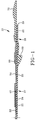
- Figure 1 illustrates one half of the laminate shown in cross section as taken along lines 1-1 of Figure 2A, the laminate being a carcass for a pneumatic tire.
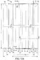
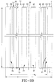
- Figure 2A is a partial plan view of the carcasses inner surface with components attached.
- Figure 2B is a partial plan view of the carcasses outer surface with components attached, both views Figure 2A and 2B being slightly inclined to depict the cut ends 12 and 14.
- Figures 3A,3B,3C and 3D are enlarged transverse views of the carcass being cut by the cutting element.
- Figures 4A and 4B are perspective views of the carcass being cylindrically formed on a building drum depicting both cut ends, Fig. 4A showing a portion of the cut ends 12,14 prior to being spliced.
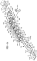
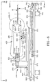
- Figure 5 is an illustration of the preferred apparatus employed to form and assemble the carcass.
- Figure 6 is a front view of the preferred cutting apparatus, made in accordance to the invention.
- Fig. 6A is a top view of the apparatus of Fig. 6.
- Fig. 6B is an end view with the cutting means oriented at an angle ⁇ .
- Fig. 6C is an end view with the cutting means oriented at an angle ⁇ .
- Figure 7 is an enlarged view cutting means of the apparatus shown in Figure 6.
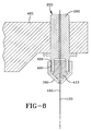
- Figure 8 is an enlarged fragmentary view partially shown in cross section, of the securing means or collets shown in Figures 6 and 7.
- Apex means an elastomeric filler located radially above the bead core and between the plies and the turnup ply.
- Bead means that part of the tire comprising an annular tensile member wrapped by ply cords and shaped, with or without other reinforcement elements such as flippers, chippers, apexes, toe guards and chafers, to fit the design rim.
- Belt structure means at least two annular layers or plies of parallel cords, woven or unwoven, underlying the tread, unanchored to the bead, and having both left and right cord angles in the range from 17° to 27° with respect to the equatorial plane of the tire.
- Carcass means an unvulcanized laminate of tire ply material and other tire components cut to length suitable for splicing, or already spliced, into a cylindrical or toroidal shape. Additional components may be added to the carcass prior to its being vulcanized to create the molded tire.
- Chips refers to narrow strips of material placed around the outside of the bead to protect cord plies from the rim, distribute flexing above the rim, and to assist in sealing the tire.
- Core means one of the reinforcement strands of which the plies in the tire are comprised.
- Innerliner means the layer or layers of elastomer or other material that form the inside surface of a tubeless tire and that contain the inflating fluid within the tire.
- Ply means a continuous layer of rubber-coated parallel cords.
- Ring and radially mean directions radially toward or away from the axis of rotation of the tire.
- Ring ply tire means a belted or circumferentially-restricted pneumatic tire in which the ply cords which extend from bead to bead are laid at cord angles between 65° and 90° with respect to the equatorial plane of the tire.
- Shader means the upper portion of sidewall just below the tread edge.
- Shader gum strip means an elastomeric reinforcement located in the shoulder region of the carcass.
- “Sidewall” means that portion of a tire between the tread and the bead.
- Thread means a rubber component which when bonded to a tire carcass includes that portion of the tire that come into contact with the road when the tire is normally inflated and under normal load.
- FIGs. 1, 2A,2B and 3A,3B,3C and 3D there is illustrated an intermediate article of manufacture 10, the intermediate article of manufacture 10 being a cut-to-length laminate, the cut-to-length laminate being a carcass 10 for a radial ply pneumatic tire.
- Fig. 1 illustrates the intermediate article of manufacture 10, the article as shown is one-half of a tire carcass 10, the portion of the carcass not illustrated being identical to the illustrated portion.
- the figure shows the carcass 10 as a flat laminate composite structure having first and second longitudinal ends 12,14 and comprising many elastomeric components. As shown all the components are either sheets or strips of material of substantially the same length. Each component shown is precisely located laterally relative to one another.
- the carcass material 10A when manufactured as shown in Fig. 5, can be made into a continuous roll 210.
- the carcass material 10A can then be, in its preassembled state, stored in large rolls 210 which when sent to a tire building station is cut to a precise length (L) by the unique cutting apparatus 100 of the present invention.
- the cut-to-length carcass 10 as shown in Figs. 2A and 2B is then formed into a cylindrical shape as shown in Figs. 4A and 4B.
- Fig. 1 depicts a cord reinforced elastomeric member 20, the elastomeric member being a ply for a pneumatic tire, the ply 20 being reinforced with parallel cords 22 which are encapsulated in unvulcanized rubber 24.
- the ply 20 has a width (W p ) and a length (L).
- the ply 20 has a pair of turnup portions 26 located at the lateral extremes of the ply 20. Each turnup portion 26 extends axially outwardly to a lateral end 29 of the ply 20.
- Attached to an outer surface 21 of the ply 20 is a pair of apexes 30.
- the apexes 30 are located on the ply adjacent to the turnup region 26 at a position to wrap about and primarily above a bead at a later tire building assembly procedure.
- the bead preferably employed is a cable bead type.
- Axially inward of the apex 30 and attached to an inner surface 23 of the ply is a pair of shoulder gum strips 40.
- the shoulder gum strips act as a rubber reinforcement in the shoulder portion 27 of the carcass 10.
- a liner component 50 is attached to the ply and over the shoulder gum strips 40.
- the liner 50 creates an air impervious barrier for the radially inner air chamber of the tubeless type tire.
- the liners are generally comprised of halobutyl rubber.
- the liner 50 has an axial width narrower than the ply 20. The liner width is sufficient to traverse axially outward of the beads when the tire is formed thus forming an air tight chamber between the tire and the wheel upon assembly.
- a chafer component 60 is shown at each lateral end 51, 52 of the liner 50.
- the chafer is attached to the liner 50, to the inner surface 23 of the ply 20, and slightly overlaps the sidewall component 70.
- the chafer 60 is positioned axially to provide a tough rubber reinforcement between the tire and the rim flange of the wheel and is accordingly located in the bead region of the tire.
- a sidewall component 70 is shown attached to the ply and extends laterally outward of the lateral ends 29 of the ply 20.
- the sidewall 70 is slightly overlapped by the chafer 60.
- a whitewall strip 80 and a cover strip 90 may be added to the carcass material 10A as shown in Fig. 5.
- the apex 30 be added at a later stage as is shown in Fig. 5. This enables the carcass material 10A to be wound into large rolls 210 without any distortion of the calendered components.
- an apex 30 and cable bead it is believed preferable to couple the carcass assembly apparatus 200 of Fig. 5 to one or more tire building machines without requiring the carcass material 10A to be rolled onto the spool 210.
- This enables the cut-to-length carcass 10 to be manufactured free of any potential distortions caused by handling and storage. In the latter case where an apex 30 is employed, the cutting of the article should occur between the forming of the carcass material 10A and applying the cut-to-length carcass 10 to the tire building machine.
- the above description of the carcass material 10A includes all the elastomeric components required to build a tubeless tire carcass 10 as it is defined in this patent application.
- laminate 10A or carcass material 10A as used throughout this application refer to the assembly of components prior to being cut to a predetermined length. Once cut to length, the term carcass 10 is used to refer to the article which when formed into a cylindrical shape on a tire building drum 5 becomes a carcass for a radial ply tire.
- a supported laminate 10A is cut forming a first inclined surface or end 12, moved a predetermined distance in a direction parallel to its length and after being so moved, the laminate 10A is cut a second time, thereby forming a cut section of laminate, hereinafter called a carcass 10, having surface areas at the sections opposite ends 12,14, the surface areas 12,14 being spaced a predetermined distance required to enable the ends 12,14 to be spliced together in forming a cylindrical carcass 10 from the cut section.
- a carcass 10 having surface areas at the sections opposite ends 12,14, the surface areas 12,14 being spaced a predetermined distance required to enable the ends 12,14 to be spliced together in forming a cylindrical carcass 10 from the cut section.
- Figs. 2A and 2B depict the first end 12 and the second end 14 respectively of the carcass 10. Both ends 12 and 14 are cut along an axial or a lateral extending substantially straight line path, the path being substantially parallel to the cords 22 of the ply 24. This substantially straight line cutting creates a first end or surface area 12 and a second end or surface area 14.
- the surface areas 12 and 14 are inclined at an angle ⁇ greater than 60° relative to a normal plane (NP), the normal plane (NP) being perpendicular to the ply 20 and substantially parallel to the cords 22 of the ply 20. In the preferred embodiment the angle ⁇ is about 80°.
- This high angle of inclination provides a large surface area of adhesion between the two ends 12,14 which are spliced at the tire building drum 5 as shown in Figs. 4A and 4B.
- the carcass assembly 10 is shown wrapped about a tire building drum 5.
- the carcass ends 12 and 14 have two inclined substantially flat planar surfaces lying in planes P.
- the operator splices the ends 12 and 14 together along the plane P.
- the preferred method of cutting creates ribs or ridges 81 and grooves or valleys 82 along the cut surfaces 12 and 14.
- the substantially parallel ridges 81 and valleys 82 further enhance the surface adhesion.
- Figs. 3A,3B there is shown an enlarged transverse view of the carcass material 10A being cut by a cutting element 120, the cutting element as shown being an oscillating wire 120.
- the oscillating wire 120 cuts a roll of carcass material 10A into cut-to-length carcasses 10.
- Fig. 6 shows a front view of the preferred cutting apparatus 100 according to the invention.
- the preferred apparatus 100 includes cutting means 102 which includes a cutting element 120.
- the cutting element 120 is preferably a wire made of high tensile steel and has a first end 140 and a second end 160.
- the wire 120 is preferably round in the cross section and has a diameter between .2 millimeters and 1.3 millimeters.
- the preferred wire of this embodiment has a diameter of .3 millimeter (.012 inches) and a smooth surface finish.
- the first and second ends 140,160 of the wire 120 are secured within securing means.
- the preferred securing means of this embodiment are collets 220,240. With reference to Fig. 8, an enlarged view of collet 220 is illustrated. The following description of collet 220 also applies to collet 240.
- the collet 220 includes the first inner cylindrical housing 280 having an outer threaded surface 320.
- the collet 220 also includes a second outer cylindrical housing or thumb nut 380 having an inner threaded surface 400 for engaging the threads on the outer surface 320 of the first housing 280.
- the thumb nut 380 can be rotated relative to the first housing 280 to secure and tension the second end 160 of the wire 120 within a collet body 410.
- the wire 120 is placed in tension when in normal operation.
- the wire 120 is shown in an inclined position, i.e., the wire makes an angle ⁇ with respect to a plane (NP), plane (NP) being perpendicular to the cord reinforced elastomeric ply 20 and parallel to the cords 22 within that material.
- the angle ⁇ preferably is greater than 60° although the preferred angle is greater than 70°, essentially about 80°.
- Some experimental tires were made having a laminate carcass 20 cut an angle ⁇ of 82°.
- the cut ends adjacent the cord 22 actually bend the wire cutter 120 such that a small fraction of the cut end does not lay in the plane P, the cut ends 12 and 14 nevertheless are substantially entirely in plane P except for this small deviation at the cords 22. Accordingly for the invention the cuts are considered substantially linear.
- the laminate 10A is cut along a majority of its width and thickness while maintaining the cutting element 120 that engages the laminate 10A at an angle ⁇ as shown in Figs. 3B, 3C, and 3D. These cuts are best accomplished if the laminate 10A is supported by a surface, preferably being supported on both sides of the cutting element 120. As shown in Fig. 6C, the support means 900 is slotted to allow the cutting element to pass through the laminate 10A. If the cutting action has a high peak to peak amplitude, it may be desirable to clamp or hold the laminate to the support means 900.
- the arms 420 and 480 are oscillated for reciprocating movement of the wire 120 at a predetermined oscillation rate.
- the means 600 for creating reciprocating movement is an eccentric 602 which is affixed to a crank gear 652 which is connected to a second gear counter balance 650 attached to an output shaft 640 of a variable speed motor 680.
- the eccentric 602 is pivotally connected to the first arm 420 by a crank arm 620.
- the variable speed motor 680 can be adjusted, the shaft 640 rotated thereby, so that the oscillating rate can vary up to about 2,000 cycles per minute while having a full peak-to-peak amplitude up to 2.5 cm.
- the oscillating rate is adjustable based on parameters such as the thickness and type of elastomeric member being cut and the transverse speed of the wire 120.
- One preferred combination is an oscillating rate of 1,200 cycles per minute and a transfer speed of about 1 centimeter per second.
- the cutting means 102 further comprises a slidable frame 520 and a means 700 for creating relative motion between the wire 120 and the elastomeric material to be cut by the cutting means 102.
- the means 700 comprises a ball screw 740 attached to pillow blocks 751, the ball screw 740 being driven by a variable speed motor 780 which powers a belt assembly 750 which is connected to the ball screw 740.
- the frame 520 is mounted on linear bearings 871 slidably supported on rods 870 which are fixed in shaft brackets 820, the brackets 820 being mounted on a stationary support 880 to provide low friction movement of the frame 520 relative to the stationary support.
- an elongated laminate 10A consisting of elastomeric components and a cord reinforced ply suitable for use as a tire carcass 10 is placed on a means 900 for supporting the laminate
- the means 900 may be a substantially flat plate or table having a slot for the cutting element 120 to traverse, the slotted plate supporting the laminate 10A while it is being cut.
- the motor 680 is started causing the crank arm 620 to oscillate a "C" arm 450, the "C" arm 450 having a first arm 420 which is integrally part of or connected to a second arm 480 by a center link 540 causing the second arm to oscillate to provide for oscillation of the cutting wire 120.
- the "C” arm 450 can be structurally lightened by machining away or milling material away from the "C” arm 450, preferably while maintaining the arms 450 structural rigidity. For this purpose a plurality of holes or slots can be cut into the "C” arm 450.
- the motor 780 is then actuated for moving the frame 520 to the right as shown toward a position adjacent to motor 780 and to engagement with the elastomeric laminate 10.
- the "C” arm 450 can have a means for oscillating the wire 120 only, the means being a small high speed pneumatic cylinder which is attached directly to the wire.
- the means (not illustrated) can oscillate the wire 120 in a similar fashion as the above-described mechanism.
- the oscillating wire 120 engages the elastomeric laminate or the carcass material 10A it forms a slit in the material. Then, as the wire advances through the carcass material 10A, the wire 120 displaces the material ahead of the slit in small increments so that the wire 120 can advance evenly. It is believed that cutting is facilitated by the adherence of a contact layer of the elastomeric material to the wire 120 which takes place until the limit of shear stress for contact layer is reached. As shown in Fig. 4A the cut splice surface may be striated by the process which provides a surface with parallel rib or ridges 81 and groove or valleys 82 smeared by the oscillating reciprocating wire 120.
- the preferred wire 120 has a smooth outer surface which is believed to enhance this rubber smearing action.
- the use of a grit or roughened surfaced wire 120 would also provide a proper angular cut surface, however, these cutting wires are more expensive and, therefore, are not preferred.
- the cut surface being smeared is found to be desirable for splicing cut ends 12,14 of the carcass 10.
- the oscillating wire 120 is maintained at a constant angle throughout the cutting of the carcass 10 it has also been determined that it is preferable to change or alter the orientation of the wire relative to the ply just prior to the wire 120 entering into cutting engagement of the ply 20. As shown in Fig. 3A, if the wire 120 is reoriented to an angle ⁇ , ⁇ being less than the angle ⁇ , it has been determined that the wire 120 will reliably enter into the cord reinforced ply material in a repeatable fashion. Once entry into the ply 20 is made the oscillating cutting wire 120 can then be reoriented back to the angle ⁇ as shown in Fig. 3B and a complete cutting across the axial width of the member can be finished as shown in Fig.
- the oscillating wire 120 should preferably be oriented at an angle ⁇ , ⁇ being less than 45° relative to the plane (NP) just prior to the wire entering into the ply cord region, ⁇ preferably the wire being oriented about 0° relative to the plane (NP). This ensures that the oscillating wire 120 does not impact or cut into a cord 22 upon entry, thereby preventing the oscillating wire cutting means from damaging the laminate.
- the apparatus 100 as described above, is capable of cutting rather thin cord reinforced elastomeric sheet material.
- a means 960 can be provided to set or fix the angular orientation of the cutting element 120. Additionally, the means 960 can be provided to change the orientation of the cutting element 120 as it cuts.
- the means 960 as shown is a actuating motor connected to the belt assembly 950. When actuated, the motor 960 can rotate the belt 950 from a first orientation to a second orientation and can reverse orientation upon reactivation.
- a proximity switch 970 is triggered as the cutting means traverses across the laminate 10A thus activating the motor 960.
- the oscillating wire cutter 120 can enter the laminate 10A oriented as shown in Fig.
- the oscillating wire cutter Upon entry into the cord reinforced ply a short distance, the oscillating wire cutter traverses and can be actually guided through the cutting process by maintaining contact with an adjacent rubberised cord.
- the rubberized cord acts as a guide for the oscillating wire cutter as is shown in Fig. 3B.
- the oscillating wire cutter 120 being oriented at the relatively high angle ⁇ over substantially the entire width of the laminate 10A enables the reinforced member to be cut at an angle heretofore believed to be unachievable.
- This large angular cut provides substantially flat planar surfaces 12,14 lying in the plane P for splicing a cylindrical carcass 10. These surfaces 12,14 provide excellent adhesion and have enabled the carcass components be laminated directly onto the cord reinforced ply stock 20 prior to cutting the structure 10A. This greatly facilitates the manufacture of a pneumatic tire carcass 10 and results in extremely high levels of efficiency.
- the oscillating action of the wire 120 tends to smear the rubber as it cuts the elastomeric material. Therefore, when cutting through a carcass 10 having a whitewall or outline white letter strip component 80 it is believed that the smearing must be kept to a minimum. Since this white material is axially outboard of the ply end 29, it is possible to simply guillotine cut that portion of the sidewall and then let the inclined wire 120 pass through the pre-cut slit prior to the wire 120 initiating its oscillating cutting of the remainder of the carcass material 10A.
- the cutting must be such as to prevent smearing of the white material along the splice lines 14,16.
- the apparatus and method of cutting a cord reinforced elastomeric member as disclosed is extremely simple and reliable and yet provides for a splice joint that is superior to those known in the prior art.
- the cutting means 102 may employ an ultrasonic cutter, a water jet cutter, a laser cutter or any number of alternative cutting elements 120. While such alternative cutting means may be within the scope of the invention it must be remembered that the cutting action should not damage the reinforcement cords. Applicants have attempted several alternatives to the smooth cutting wire 120, however, these alternatives appear to be more complicated and more prone to damaging cords.
Applications Claiming Priority (2)
| Application Number | Priority Date | Filing Date | Title |
|---|---|---|---|
| US36921195A | 1995-01-05 | 1995-01-05 | |
| US369211 | 2003-02-14 |
Publications (3)
| Publication Number | Publication Date |
|---|---|
| EP0737564A2 true EP0737564A2 (fr) | 1996-10-16 |
| EP0737564A3 EP0737564A3 (fr) | 1997-03-19 |
| EP0737564B1 EP0737564B1 (fr) | 2002-05-29 |
Family
ID=23454553
Family Applications (1)
| Application Number | Title | Priority Date | Filing Date |
|---|---|---|---|
| EP95203571A Expired - Lifetime EP0737564B1 (fr) | 1995-01-05 | 1995-12-28 | Procédé et dispositif pour couper un produit élastomère stratifié renforcé par des cordes |
Country Status (20)
| Country | Link |
|---|---|
| US (2) | US5746101A (fr) |
| EP (1) | EP0737564B1 (fr) |
| JP (1) | JPH08332678A (fr) |
| KR (1) | KR960029082A (fr) |
| CN (1) | CN1146949A (fr) |
| AR (1) | AR000546A1 (fr) |
| AT (1) | ATE218097T1 (fr) |
| AU (1) | AU692010B2 (fr) |
| BR (1) | BR9600014A (fr) |
| CA (1) | CA2145794A1 (fr) |
| CZ (1) | CZ3196A3 (fr) |
| DE (1) | DE69526847D1 (fr) |
| FI (1) | FI960037A (fr) |
| MA (1) | MA23756A1 (fr) |
| NO (1) | NO960032L (fr) |
| NZ (1) | NZ280784A (fr) |
| PL (1) | PL179313B1 (fr) |
| TR (1) | TR199600011A1 (fr) |
| TW (1) | TW340086B (fr) |
| ZA (1) | ZA9510984B (fr) |
Cited By (4)
| Publication number | Priority date | Publication date | Assignee | Title |
|---|---|---|---|---|
| WO1999061229A1 (fr) * | 1998-05-22 | 1999-12-02 | The Goodyear Tire & Rubber Company | Jonction a angle tres ferme pour semelles |
| US6109322A (en) * | 1995-12-15 | 2000-08-29 | The Goodyear Tire & Rubber Company | Laminate composite structure for making an unvulcanized carcass for a radial ply tire as an intermediate article of manufacture |
| US6336488B1 (en) | 1995-12-15 | 2002-01-08 | The Goodyear Tire & Rubber Company | Unvulcanized noncord reinforced subassembly for incorporation in a tire casing |
| EP1291161A2 (fr) * | 2001-09-05 | 2003-03-12 | The Goodyear Tire & Rubber Company | Procédé et dispositif de fabrication d'articles sans fin en caoutchouc renforcé |
Families Citing this family (23)
| Publication number | Priority date | Publication date | Assignee | Title |
|---|---|---|---|---|
| US6592704B1 (en) | 1999-03-03 | 2003-07-15 | The Goodyear Tire & Rubber Company | Forming splice joints for elastomeric materials |
| AU2800799A (en) * | 1999-03-03 | 2000-09-21 | Goodyear Tire And Rubber Company, The | Forming splice joints for elastomeric materials |
| JP3303294B2 (ja) * | 1999-06-11 | 2002-07-15 | 株式会社東京精密 | 半導体保護テープの切断方法 |
| US6755105B2 (en) * | 2001-06-01 | 2004-06-29 | The Goodyear Tire & Rubber Company | Method and apparatus for cutting elastomeric materials and the article made by the method |
| DE10226148B4 (de) * | 2002-06-13 | 2011-11-17 | Tetra Laval Holdings & Finance S.A. | Vorrichtung zum Verkleben zweier Verpackungsmaterialbahnen |
| FR2869565B1 (fr) * | 2004-04-28 | 2007-08-10 | Eurocopter France | Protection d'une structure composite aux impacts |
| US20060070504A1 (en) * | 2004-10-01 | 2006-04-06 | Downing Daniel R | Apparatus for cutting elastomeric materials |
| CN100528498C (zh) * | 2004-10-08 | 2009-08-19 | 米其林技术公司 | 预组装橡胶产品的切割 |
| KR100645108B1 (ko) * | 2004-10-11 | 2006-11-10 | 김미옥 | 추락방지망 설치구조 |
| US7524398B2 (en) * | 2004-12-23 | 2009-04-28 | The Goodyear Tire & Rubber Company | Apparatus for making tire components, and a tire |
| US8561511B2 (en) * | 2004-12-23 | 2013-10-22 | The Goodyear Tire & Rubber Company | Anvil with vacuum width adjustment |
| US7455002B2 (en) * | 2004-12-23 | 2008-11-25 | The Goodyear Tire & Rubber Company | Method for cutting elastomeric materials and the article made by the method |
| US20060137804A1 (en) * | 2004-12-23 | 2006-06-29 | Downing Daniel R | Method for making tire ply |
| US20060137814A1 (en) * | 2004-12-23 | 2006-06-29 | Downing Daniel R | Method for making reinforced elastomeric materials |
| KR100714422B1 (ko) | 2006-04-13 | 2007-05-04 | 한국타이어 주식회사 | 카카스 절단각도 변경용 재단기 |
| US7811399B2 (en) * | 2006-09-21 | 2010-10-12 | The Goodyear Tire & Rubber Company | Tire component cutter apparatus and method of cutting |
| US7823490B2 (en) * | 2006-10-04 | 2010-11-02 | The Boeing Company | Cutting sequence for net trimming a composite layup at an oblique angle |
| ATE543636T1 (de) * | 2007-03-29 | 2012-02-15 | Daiso Co Ltd | Maschine zur herstellung einer schrägkante auf einem mit faltlinie versehenen filmmaterial |
| CN101666034B (zh) * | 2009-09-25 | 2011-05-25 | 天津赛象科技股份有限公司 | 90°纤维帘布裁断机 |
| NL2004213C2 (nl) * | 2010-02-09 | 2011-08-10 | Vmi Holland Bv | Werkwijze voor het vervaardigen van een band van aan elkaar gelaste strips. |
| CN104325489B (zh) * | 2014-10-15 | 2017-01-11 | 成都东方凯特瑞环保催化剂有限责任公司 | 一种软态坯料切割方法及其切割装置 |
| US20160230238A1 (en) * | 2014-10-16 | 2016-08-11 | L. Ronnie Nettles | Leather Lace Beveling Apparatus and Method |
| CN109094156B (zh) * | 2018-07-24 | 2020-11-03 | 中国航空工业集团公司基础技术研究院 | 一种具有整体赋型面的组合结构工艺盖板 |
Family Cites Families (49)
| Publication number | Priority date | Publication date | Assignee | Title |
|---|---|---|---|---|
| US1320121A (en) * | 1919-10-28 | brucker | ||
| US1353934A (en) * | 1917-12-29 | 1920-09-28 | Morris Tire Machinery Company | Method and machine for making the rubber elements for tires, laminated tire-treads, &c. |
| US1353769A (en) * | 1919-06-09 | 1920-09-21 | Dunlop Rubber Co | Manufacture of solid rubber tires |
| US1393164A (en) * | 1919-09-02 | 1921-10-11 | Racine Tool & Machine Co | Tire-cutting machine |
| US1502120A (en) * | 1920-04-05 | 1924-07-22 | Ralph T Ingalls | Machine for cutting rubber and the like |
| US1667009A (en) * | 1924-02-16 | 1928-04-24 | Goodrich Co B F | Method and apparatus for making laminated strips |
| US1730307A (en) * | 1924-12-17 | 1929-10-01 | Firestone Tire & Rubber Co | Stock-assembling device |
| US1770895A (en) * | 1926-07-30 | 1930-07-22 | Morgan & Wright | Method of building tires and product |
| US2754887A (en) * | 1953-12-24 | 1956-07-17 | Firestone Tire & Rubber Co | Method of making a tubeless tire |
| US3234769A (en) * | 1962-07-17 | 1966-02-15 | Kocks Gmbh Friedrich | Rolling-mill stand with exchangeable rolls |
| US3027289A (en) * | 1959-02-10 | 1962-03-27 | Goodrich Co B F | Tire building method and apparatus |
| US2941465A (en) * | 1959-03-25 | 1960-06-21 | Perkins & Son Inc B F | Removable roll means for calender |
| US3237673A (en) * | 1961-06-05 | 1966-03-01 | Goodyear Tire & Rubber | Tubeless tire and method of splicing the inside plies of same |
| GB950578A (en) * | 1961-06-05 | 1964-02-26 | Goodyear Tire & Rubber | Lap seam for coated cord fabric and method for making same |
| FR1516890A (fr) * | 1966-12-29 | 1968-02-05 | Pneumatiques Caoutchouc Mfg | Pneumatique et son procédé de fabrication |
| US3413921A (en) * | 1967-03-23 | 1968-12-03 | Dymo Industries Inc | Duplicating machine printing drum mounting construction |
| FR1549394A (fr) * | 1967-10-09 | 1968-12-13 | ||
| US3803965A (en) * | 1972-05-24 | 1974-04-16 | Steelastic Co | Apparatus for producing reinforced fabric |
| US4030653A (en) * | 1973-09-17 | 1977-06-21 | The Goodyear Tire & Rubber Company | Method and apparatus for splicing tire cord fabric |
| US4210042A (en) * | 1977-11-25 | 1980-07-01 | The Goodyear Tire & Rubber Company | Method for parting ply stock between side-by-side cords or wires |
| DE2843904C2 (de) * | 1978-10-07 | 1984-04-19 | Elmar Dr. 8000 München Messerschmitt | Vorrichtung zum Schneiden von streifenförmigen Werkstücken aus Gummi oder einem elastischen Kunststoff |
| US4232723A (en) * | 1978-10-10 | 1980-11-11 | The Goodyear Tire & Rubber Company | Isostable tubular tire |
| JPS5614027A (en) * | 1979-07-17 | 1981-02-10 | Morikoshi Yutaka | Roll exchanging apparatus for cold roll forming machine |
| US4393450A (en) * | 1980-08-11 | 1983-07-12 | Trustees Of Dartmouth College | Three-dimensional model-making system |
| US4465536A (en) * | 1981-05-01 | 1984-08-14 | Bridgestone Tire Company, Limited | Method of and apparatus for feeding rubbery strip to tire-building drum |
| US4466473A (en) * | 1983-02-22 | 1984-08-21 | The General Tire & Rubber Company | Tire ply splice construction and method of making the same |
| JPS59195406A (ja) * | 1983-04-20 | 1984-11-06 | Yokohama Rubber Co Ltd:The | 乗用車用空気入りラジアルタイヤ |
| US4857123A (en) * | 1983-05-09 | 1989-08-15 | The Firestone Tire & Rubber Company | Method for ply application |
| IT8322073V0 (it) * | 1983-06-09 | 1983-06-09 | Pomini Farrel Spa | Dispositivo atto alla sostituzione di cilindri di gabbie di laminazione. |
| DE3574463D1 (de) * | 1984-04-28 | 1990-01-04 | Schloemann Siemag Ag | Walzgeruest. |
| DE3416212C2 (de) * | 1984-05-02 | 1986-12-18 | Kleinewefers Gmbh, 4150 Krefeld | Vorrichtung zum Auswechseln mindestens einer Walze für einen Kalander |
| DE3444612A1 (de) * | 1984-12-07 | 1986-06-12 | Recticel Deutschland GmbH, 5342 Rheinbreitbach | Vertikalschneidemaschine fuer schaumstoffe |
| US4768575A (en) * | 1985-12-17 | 1988-09-06 | Highland Industries, Inc. | Pneumatic tubeless tire and method of splicing together the ends of a carcass fabric thereof |
| ES2033797T3 (es) * | 1986-03-20 | 1993-04-01 | Rhone-Poulenc Viscosuisse Sa | Carcasa de neumatico. |
| US4733709A (en) * | 1986-07-25 | 1988-03-29 | General Tire, Inc. | Radial tire with a reinforced butt splice carcass ply and method of making |
| JPH07115425B2 (ja) * | 1986-09-24 | 1995-12-13 | 株式会社ブリヂストン | タイヤ成形方法および装置 |
| US4813319A (en) * | 1987-04-01 | 1989-03-21 | The Firestone Tire & Rubber Company | Method and apparatus for transversely cutting strips of deformable material |
| IT218578Z2 (it) * | 1987-08-04 | 1992-06-23 | Danieli Off Mecc | Gabbia trasformabile a quarto e universale e linea di laminazione adottante tale gabbia trasformabile |
| FR2624051B1 (fr) * | 1987-12-03 | 1990-04-06 | Michelin & Cie | Procede pour raccorder bout a bout les bords d'un tissu caoutchoute, destine a la fabrication d'une armature de carcasse, et pneumatique a armature de carcasse radiale obtenu |
| JP2719918B2 (ja) * | 1988-01-18 | 1998-02-25 | 株式会社ブリヂストン | シート状材料の切断装置 |
| US5029502A (en) * | 1989-05-26 | 1991-07-09 | Mitsubishi Jukogyo Kabushiki Kaisha | Method and apparatus for cutting wire-embedded member for use in tire |
| US5030079A (en) * | 1989-10-27 | 1991-07-09 | The Goodyear Tire & Rubber Company | Roller die extrusion and calendering apparatus |
| US5062462A (en) * | 1990-01-19 | 1991-11-05 | The Goodyear Tire & Rubber Company | Pneumatic tire made by butt-splicing structural members and a method therefor |
| JP3076360B2 (ja) * | 1990-08-21 | 2000-08-14 | 株式会社ブリヂストン | コード入りゴムシートの切断不良検出方法 |
| JP3124560B2 (ja) * | 1990-12-28 | 2001-01-15 | 株式会社ブリヂストン | プライ部材の成型方法 |
| DE4142723A1 (de) * | 1991-12-21 | 1993-07-01 | Continental Ag | Verfahren und vorrichtung zum ablaengen einer materialbahn aus reifenaufbaumaterial |
| JP3087088B2 (ja) * | 1992-02-14 | 2000-09-11 | 横浜ゴム株式会社 | 空気入りラジアルタイヤ |
| US5327807A (en) * | 1993-08-20 | 1994-07-12 | P & F Brother Industrial Corporation | Scroll saw with saw blade fastening and tension adjusting device |
| US5638732A (en) * | 1994-09-02 | 1997-06-17 | The Goodyear Tire & Rubber Company | Apparatus for cutting of elastomeric materials |
-
1995
- 1995-03-29 CA CA 2145794 patent/CA2145794A1/fr not_active Abandoned
- 1995-12-19 TW TW084113536A patent/TW340086B/zh active
- 1995-12-22 MA MA24110A patent/MA23756A1/fr unknown
- 1995-12-26 AR AR33480695A patent/AR000546A1/es unknown
- 1995-12-27 ZA ZA9510984A patent/ZA9510984B/xx unknown
- 1995-12-28 AT AT95203571T patent/ATE218097T1/de active
- 1995-12-28 EP EP95203571A patent/EP0737564B1/fr not_active Expired - Lifetime
- 1995-12-28 DE DE69526847T patent/DE69526847D1/de not_active Expired - Lifetime
-
1996
- 1996-01-03 BR BR9600014A patent/BR9600014A/pt not_active IP Right Cessation
- 1996-01-04 FI FI960037A patent/FI960037A/fi unknown
- 1996-01-04 NO NO960032A patent/NO960032L/no unknown
- 1996-01-04 NZ NZ280784A patent/NZ280784A/en unknown
- 1996-01-04 KR KR1019960000036A patent/KR960029082A/ko not_active Application Discontinuation
- 1996-01-04 AU AU40817/96A patent/AU692010B2/en not_active Ceased
- 1996-01-04 PL PL96312150A patent/PL179313B1/pl unknown
- 1996-01-05 CN CN96104033A patent/CN1146949A/zh active Pending
- 1996-01-05 CZ CZ9631A patent/CZ3196A3/cs unknown
- 1996-01-05 TR TR96/00011A patent/TR199600011A1/xx unknown
- 1996-01-05 JP JP35796A patent/JPH08332678A/ja active Pending
- 1996-11-29 US US08/758,401 patent/US5746101A/en not_active Expired - Fee Related
- 1996-12-19 US US08/770,634 patent/US5746102A/en not_active Expired - Fee Related
Cited By (5)
| Publication number | Priority date | Publication date | Assignee | Title |
|---|---|---|---|---|
| US6109322A (en) * | 1995-12-15 | 2000-08-29 | The Goodyear Tire & Rubber Company | Laminate composite structure for making an unvulcanized carcass for a radial ply tire as an intermediate article of manufacture |
| US6336488B1 (en) | 1995-12-15 | 2002-01-08 | The Goodyear Tire & Rubber Company | Unvulcanized noncord reinforced subassembly for incorporation in a tire casing |
| WO1999061229A1 (fr) * | 1998-05-22 | 1999-12-02 | The Goodyear Tire & Rubber Company | Jonction a angle tres ferme pour semelles |
| EP1291161A2 (fr) * | 2001-09-05 | 2003-03-12 | The Goodyear Tire & Rubber Company | Procédé et dispositif de fabrication d'articles sans fin en caoutchouc renforcé |
| EP1291161A3 (fr) * | 2001-09-05 | 2004-07-21 | The Goodyear Tire & Rubber Company | Procédé et dispositif de fabrication d'articles sans fin en caoutchouc renforcé |
Also Published As
| Publication number | Publication date |
|---|---|
| TR199600011A1 (tr) | 1996-10-21 |
| MA23756A1 (fr) | 1996-07-01 |
| EP0737564A3 (fr) | 1997-03-19 |
| FI960037A (fi) | 1996-07-06 |
| CA2145794A1 (fr) | 1996-07-06 |
| KR960029082A (ko) | 1996-08-17 |
| US5746102A (en) | 1998-05-05 |
| FI960037A0 (fi) | 1996-01-04 |
| AU692010B2 (en) | 1998-05-28 |
| NO960032L (no) | 1996-07-08 |
| ATE218097T1 (de) | 2002-06-15 |
| DE69526847D1 (de) | 2002-07-04 |
| TW340086B (en) | 1998-09-11 |
| PL312150A1 (en) | 1996-07-08 |
| JPH08332678A (ja) | 1996-12-17 |
| EP0737564B1 (fr) | 2002-05-29 |
| NO960032D0 (no) | 1996-01-04 |
| CZ3196A3 (en) | 1996-11-13 |
| NZ280784A (en) | 1997-10-24 |
| US5746101A (en) | 1998-05-05 |
| CN1146949A (zh) | 1997-04-09 |
| BR9600014A (pt) | 1998-01-21 |
| AU4081796A (en) | 1996-07-11 |
| AR000546A1 (es) | 1997-07-10 |
| PL179313B1 (pl) | 2000-08-31 |
| ZA9510984B (en) | 1996-06-25 |
Similar Documents
| Publication | Publication Date | Title |
|---|---|---|
| US5746101A (en) | Method for cutting a cord reinforced elastomeric laminate | |
| US7501033B2 (en) | Chipper and apex subassembly as an intermediate article of manufacture | |
| US7811399B2 (en) | Tire component cutter apparatus and method of cutting | |
| CN100509316C (zh) | 用于切割弹性体材料的设备 | |
| US20200189215A1 (en) | Method for forming a sealant layer in a tire | |
| US7526986B2 (en) | Method for cutting elastomeric materials | |
| JP5122745B2 (ja) | タイヤコンポーネントを製造する装置およびタイヤの製造方法 | |
| JP5177973B2 (ja) | エラストマータイヤ構成部材とタイヤを製造する装置 | |
| EP1647395B1 (fr) | Procédé de fabrication de pneumatiques avec une ceinture segmentée | |
| US6592704B1 (en) | Forming splice joints for elastomeric materials | |
| US20070079921A1 (en) | Pivoting splice stitcher and method of stitching an angled splice | |
| US6109322A (en) | Laminate composite structure for making an unvulcanized carcass for a radial ply tire as an intermediate article of manufacture | |
| EP0607785B1 (fr) | Méthode et appareil pour le meulage des bords de bandes de roulement | |
| EP0868300B1 (fr) | Sous-ensemble renforce, sans cordes et non vulcanise pour incorporation dans un bandage pnematique | |
| EP1159123B1 (fr) | Formation de joints d'epissure pour materiaux elastomeres | |
| JP2006175873A (ja) | 補強されたエラストマ織物を製造する方法 | |
| JP4103945B2 (ja) | 空気入りラジアルタイヤ並びにその製造装置及び製造方法 | |
| US20220063223A1 (en) | Method and apparatus for forming an apex |
Legal Events
| Date | Code | Title | Description |
|---|---|---|---|
| PUAI | Public reference made under article 153(3) epc to a published international application that has entered the european phase |
Free format text: ORIGINAL CODE: 0009012 |
|
| 17P | Request for examination filed |
Effective date: 19951228 |
|
| AK | Designated contracting states |
Kind code of ref document: A2 Designated state(s): AT BE DE DK ES FR GB GR IT NL SE |
|
| PUAL | Search report despatched |
Free format text: ORIGINAL CODE: 0009013 |
|
| AK | Designated contracting states |
Kind code of ref document: A3 Designated state(s): AT BE DE DK ES FR GB GR IT NL SE |
|
| 17Q | First examination report despatched |
Effective date: 19990917 |
|
| GRAG | Despatch of communication of intention to grant |
Free format text: ORIGINAL CODE: EPIDOS AGRA |
|
| GRAG | Despatch of communication of intention to grant |
Free format text: ORIGINAL CODE: EPIDOS AGRA |
|
| GRAH | Despatch of communication of intention to grant a patent |
Free format text: ORIGINAL CODE: EPIDOS IGRA |
|
| GRAH | Despatch of communication of intention to grant a patent |
Free format text: ORIGINAL CODE: EPIDOS IGRA |
|
| GRAA | (expected) grant |
Free format text: ORIGINAL CODE: 0009210 |
|
| AK | Designated contracting states |
Kind code of ref document: B1 Designated state(s): AT BE DE DK ES FR GB GR IT NL SE |
|
| PG25 | Lapsed in a contracting state [announced via postgrant information from national office to epo] |
Ref country code: NL Free format text: LAPSE BECAUSE OF FAILURE TO SUBMIT A TRANSLATION OF THE DESCRIPTION OR TO PAY THE FEE WITHIN THE PRESCRIBED TIME-LIMIT Effective date: 20020529 Ref country code: IT Free format text: LAPSE BECAUSE OF FAILURE TO SUBMIT A TRANSLATION OF THE DESCRIPTION OR TO PAY THE FEE WITHIN THE PRE;WARNING: LAPSES OF ITALIAN PATENTS WITH EFFECTIVE DATE BEFORE 2007 MAY HAVE OCCURRED AT ANY TIME BEFORE 2007. THE CORRECT EFFECTIVE DATE MAY BE DIFFERENT FROM THE ONE RECORDED.SCRIBED TIME-LIMIT Effective date: 20020529 Ref country code: GR Free format text: LAPSE BECAUSE OF FAILURE TO SUBMIT A TRANSLATION OF THE DESCRIPTION OR TO PAY THE FEE WITHIN THE PRESCRIBED TIME-LIMIT Effective date: 20020529 Ref country code: BE Free format text: LAPSE BECAUSE OF FAILURE TO SUBMIT A TRANSLATION OF THE DESCRIPTION OR TO PAY THE FEE WITHIN THE PRESCRIBED TIME-LIMIT Effective date: 20020529 Ref country code: AT Free format text: LAPSE BECAUSE OF FAILURE TO SUBMIT A TRANSLATION OF THE DESCRIPTION OR TO PAY THE FEE WITHIN THE PRESCRIBED TIME-LIMIT Effective date: 20020529 |
|
| REF | Corresponds to: |
Ref document number: 218097 Country of ref document: AT Date of ref document: 20020615 Kind code of ref document: T |
|
| REG | Reference to a national code |
Ref country code: GB Ref legal event code: FG4D |
|
| REF | Corresponds to: |
Ref document number: 69526847 Country of ref document: DE Date of ref document: 20020704 |
|
| ET | Fr: translation filed | ||
| PG25 | Lapsed in a contracting state [announced via postgrant information from national office to epo] |
Ref country code: SE Free format text: LAPSE BECAUSE OF FAILURE TO SUBMIT A TRANSLATION OF THE DESCRIPTION OR TO PAY THE FEE WITHIN THE PRESCRIBED TIME-LIMIT Effective date: 20020829 Ref country code: DK Free format text: LAPSE BECAUSE OF FAILURE TO SUBMIT A TRANSLATION OF THE DESCRIPTION OR TO PAY THE FEE WITHIN THE PRESCRIBED TIME-LIMIT Effective date: 20020829 |
|
| PG25 | Lapsed in a contracting state [announced via postgrant information from national office to epo] |
Ref country code: DE Free format text: LAPSE BECAUSE OF FAILURE TO SUBMIT A TRANSLATION OF THE DESCRIPTION OR TO PAY THE FEE WITHIN THE PRESCRIBED TIME-LIMIT Effective date: 20020830 |
|
| NLV1 | Nl: lapsed or annulled due to failure to fulfill the requirements of art. 29p and 29m of the patents act | ||
| PG25 | Lapsed in a contracting state [announced via postgrant information from national office to epo] |
Ref country code: ES Free format text: LAPSE BECAUSE OF FAILURE TO SUBMIT A TRANSLATION OF THE DESCRIPTION OR TO PAY THE FEE WITHIN THE PRESCRIBED TIME-LIMIT Effective date: 20021128 |
|
| PG25 | Lapsed in a contracting state [announced via postgrant information from national office to epo] |
Ref country code: GB Free format text: LAPSE BECAUSE OF NON-PAYMENT OF DUE FEES Effective date: 20021228 |
|
| PLBE | No opposition filed within time limit |
Free format text: ORIGINAL CODE: 0009261 |
|
| STAA | Information on the status of an ep patent application or granted ep patent |
Free format text: STATUS: NO OPPOSITION FILED WITHIN TIME LIMIT |
|
| 26N | No opposition filed |
Effective date: 20030303 |
|
| GBPC | Gb: european patent ceased through non-payment of renewal fee |
Effective date: 20021228 |
|
| PG25 | Lapsed in a contracting state [announced via postgrant information from national office to epo] |
Ref country code: FR Free format text: LAPSE BECAUSE OF NON-PAYMENT OF DUE FEES Effective date: 20030901 |
|
| REG | Reference to a national code |
Ref country code: FR Ref legal event code: ST |