EP0737543A2 - Machining and/or assembling center - Google Patents
Machining and/or assembling center Download PDFInfo
- Publication number
- EP0737543A2 EP0737543A2 EP96105340A EP96105340A EP0737543A2 EP 0737543 A2 EP0737543 A2 EP 0737543A2 EP 96105340 A EP96105340 A EP 96105340A EP 96105340 A EP96105340 A EP 96105340A EP 0737543 A2 EP0737543 A2 EP 0737543A2
- Authority
- EP
- European Patent Office
- Prior art keywords
- satellite
- conveyor
- processing
- main conveyor
- conveyors
- Prior art date
- Legal status (The legal status is an assumption and is not a legal conclusion. Google has not performed a legal analysis and makes no representation as to the accuracy of the status listed.)
- Granted
Links
Images
Classifications
-
- B—PERFORMING OPERATIONS; TRANSPORTING
- B65—CONVEYING; PACKING; STORING; HANDLING THIN OR FILAMENTARY MATERIAL
- B65G—TRANSPORT OR STORAGE DEVICES, e.g. CONVEYORS FOR LOADING OR TIPPING, SHOP CONVEYOR SYSTEMS OR PNEUMATIC TUBE CONVEYORS
- B65G37/00—Combinations of mechanical conveyors of the same kind, or of different kinds, of interest apart from their application in particular machines or use in particular manufacturing processes
- B65G37/02—Flow-sheets for conveyor combinations in warehouses, magazines or workshops
-
- B—PERFORMING OPERATIONS; TRANSPORTING
- B23—MACHINE TOOLS; METAL-WORKING NOT OTHERWISE PROVIDED FOR
- B23P—METAL-WORKING NOT OTHERWISE PROVIDED FOR; COMBINED OPERATIONS; UNIVERSAL MACHINE TOOLS
- B23P21/00—Machines for assembling a multiplicity of different parts to compose units, with or without preceding or subsequent working of such parts, e.g. with programme control
- B23P21/004—Machines for assembling a multiplicity of different parts to compose units, with or without preceding or subsequent working of such parts, e.g. with programme control the units passing two or more work-stations whilst being composed
-
- B—PERFORMING OPERATIONS; TRANSPORTING
- B23—MACHINE TOOLS; METAL-WORKING NOT OTHERWISE PROVIDED FOR
- B23P—METAL-WORKING NOT OTHERWISE PROVIDED FOR; COMBINED OPERATIONS; UNIVERSAL MACHINE TOOLS
- B23P2700/00—Indexing scheme relating to the articles being treated, e.g. manufactured, repaired, assembled, connected or other operations covered in the subgroups
- B23P2700/50—Other automobile vehicle parts, i.e. manufactured in assembly lines
Definitions
- the invention relates to a processing and / or assembly system according to the preamble of claim 1.
- DE 40 10 024 describes a production system for the assembly and / or processing of components consisting of several individual parts, in which the individual parts or components are arranged, joined or processed on pallet inserts, the pallet inserts being arranged interchangeably on trolleys.
- the trolleys are guided along a conveyor track of a conveyor device, in which the conveyor track has parallel sections parallel to a main conveyor path, which are connected to the main conveyor path via transverse conveyor paths.
- the parallel conveying paths are each directly adjacent to a parallel parallel conveying path, which is connected via node stations to the cross conveying or parallel conveying path and the main conveying path.
- Such a system allows a relatively variable work volume for the individual work areas.
- the invention has for its object to provide a processing and / or assembly system of the type mentioned, in which, despite the constant speed of the main conveyor, the work volumes and thus the working hours, in particular manual work operations, can be varied and thus adapted to changed work tasks, in particular the manual work operations can be resolved into spatially separate units, whereby defective workpieces that arise in the respective work unit do not necessarily reach the main conveyor, but can remain within the work unit, workpieces on the main conveyor can skip predetermined work operations without delay in the course of the system, and all work stations are easily accessible for the supply of material and for the execution of auxiliary work.
- the main conveyor thus connects several satellite conveyors of generally different lengths at a point which is designed as a workpiece transfer device.
- the workpieces placed on the main conveyor by means of workpiece carriers are brought in succession from the main conveyor to the automated processing and / or assembly machines arranged on this main conveyor and to the workpiece transfer devices of the satellite conveyors also arranged on the main conveyor.
- a workpiece is only transferred from the workpiece transfer devices to the satellite conveyor if this workpiece has to be processed in the course of this satellite conveyor.
- the length of this satellite conveyor can be designed according to the scope of work to be performed on it. The length can be changed with relatively little effort and so on changing work scopes adaptable.
- the satellite conveyor can work continuously or step by step, regardless of the speed of the main conveyor. If defective workpieces appear at the end of the satellite conveyor, then these can pass through the satellite conveyor a second time to remedy the error, so that only flawless workpieces reach the main conveyor.
- a radiating to the main conveyor i.e. H. centered or comb-like, i.e. H. aligned perpendicular to a line or a herringbone, i.e. H.
- the main order of the satellite bands allows good accessibility for material and auxiliary material supply for both the main conveyor and the satellite conveyor, with good space economy of the system.
- the height is so that the work operations running on the satellite conveyor, which are essentially manual operations, can be carried out in a convenient location the satellite conveyor can be set to an ergonomically correct height for the respective work operation.
- the workpiece transfer device between the main conveyor and the satellite conveyor compensates for the height difference.
- a preferred form of the main conveyor is a rotating circular conveyor arranged on one level, the path of movement of which circumscribes an area. Automatic assembly and / or processing stations, but also the facilities for servicing and maintenance of the system are advantageously arranged within this area. Outside the area encircled by the main conveyor, the satellite conveyors are connected, which are accessible from all sides.
- main conveyor If the surface enclosed by the main conveyor is an oval with two long and two short sides, then workpiece holding devices can advantageously be arranged on the short sides.
- the satellite conveyors connect via the workpiece transfer devices to the long sides of the main conveyor, whereby they are arranged parallel to one another.
- the satellite conveyors are advantageously arranged radially outside the circle, the contact angle between the main conveyor and the satellite conveyor advantageously being the same. In this way, the workpiece transfer devices on all satellite conveyors can be designed with essentially the same components.
- the area enclosed by the satellite conveyors forms a space for a closed work team, which can communicate with the entire system through the satellite conveyor, but relative to the surroundings is shielded. This can improve the working conditions for the team's employees.
- the areas delimited by the satellite conveyors can have any shape, but they will preferably be oval or round, since in such a configuration the satellite conveyor can be made relatively simple.
- a workpiece transfer device arranged between the main conveyor and a satellite conveyor is equipped with both a workpiece removal station and a workpiece depositing station, then a workpiece can be removed from the main conveyor and transferred to the satellite conveyor and another workpiece can be transferred from the satellite conveyor to the main conveyor.
- This can be an advantage if the available space does not allow the satellite conveyors to be extended in any way, as this means that there is a greater available working length.
- the main conveyor can be shorter at this point compared to the previously described embodiment.
- the work space can be kept free for the work team located in the area.
- the working conditions can be created in such a way that good conditions for high quality are also given for manual work.
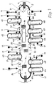
- a main conveyor 1 forms an oval on a flat corridor and thus encloses a surface 2. This surface 2 is accessible via a staircase 3 and a tunnel 4.
- the main conveyor 1 connects a number of automatic processing and / or assembly machines 51 to 59 and one Number of satellite conveyors 61 to 68, on which manual workstations 7 are arranged.
- the satellite conveyors 61 to 68 are also as flat Corrugated ovals are formed, each enclosing a surface 8.
- the main conveyor 1 and the satellite conveyors 61 to 68 convey workpiece carriers 9, which are automatically loaded with a basic equipment of material on the assembly machine 51.
- the workpiece carrier 9 with the possibly pre-fabricated and partially preassembled material placed by the assembly machine 51 is conveyed from the main conveyor 1 to a first workpiece transfer device 101, which connects the satellite conveyor 61 to the main conveyor 1.
- the workpiece transfer device 101 decides whether such work operations are required on the workpieces located on the workpiece carrier 9 that are carried out at work stations 7 of the satellite conveyor 61. This decision can be made possible by a coding of the workpiece carrier 9 which is known per se when the material is in contact with the assembly machine 51. If processing is provided at the work stations 7 of the satellite conveyor 61, then the workpiece carrier 9 is removed from a workpiece removal station of the workpiece transfer device 101 by the main conveyor 1, brought to the respective working height of the satellite conveyor 61 and placed there.
- the satellite conveyor 61 brings the workpiece carrier 9 together with the workpiece lying thereon to the successive workstations 7, the satellite conveyor 61 being able to convey continuously or step-wise depending on the type of these workstations 7.
- the workplaces for the workers who carry out the work operations at the work stations 7 are arranged within the area 8, so that a spatially closed work space is created for the work team.
- the additional materials and auxiliary materials required for these work operations are fed from outside of the surface 8 by a material feeder 11 and placed on material carriers 12. Access to the surfaces 8 can be via stairs or tunnels (not shown) or swiveling parts of the satellite conveyor.
- the transport system of the satellite conveyors can also be designed at such a height that it can be climbed comfortably.
- the respective workpiece carrier 9 again reaches the workpiece transfer device 101, where it is brought to the level of the main conveyor 1 and is converted back to the main conveyor 1 by a workpiece depositing station.
- the main conveyor 1 feeds the workpiece carrier 9 with the machined workpiece to the automatic processing and / or assembly machine 52 for further processing.
- the workpiece carrier 9 is now fed to the workpiece transfer device 102, in which the process for transfer to the satellite conveyor 62 is generally repeated in the same manner as described for the satellite conveyor 61.
- the workpiece transfer device 102 determines that the work operations of the work stations 7 arranged on the satellite conveyor 61 are not required for the workpiece currently present, for example by For example, if a particular unit is not to be attached to this workpiece, the workpiece carrier 9 is passed on from the workpiece transfer device 102 directly to the main conveyor 1, where it then meets the next processing or assembly machine 53, which is automated here.
- the processing or assembly of the workpiece, for. B. an internal combustion engine continues through the following automatic processing and / or assembly machines 54 to 59 and the workstations 7 within the satellite conveyor 63 to 68.
- the automatic processing or assembly machines 51 to 59 can be fed through material loading devices 13 material and auxiliary material are supplied.
- switch cabinets 14 for the control of the system as a whole and for the automatic processing and / or assembly machines 51 to 59 are accommodated.
- a service and maintenance center 15 is provided for the system within area 2.
- the finished workpiece e.g. B. the fully assembled internal combustion engine
- the workpiece carrier 8 runs via the main conveyor 1 again in the processing and / or assembly machine 51 into the circuit of the system.
- the invention enables a large number of exemplary embodiments.
- the arrangement of automatic processing or assembly machines and satellite conveyors can be varied as required.
- the main conveyor and the satellite conveyors can be designed as continuous conveyors or as step conveyors.
- the workpiece transfer devices can, as explained in the exemplary embodiment described above, each be provided with a workpiece removal station and a workpiece placement station, so that at the same time one workpiece is removed from the main conveyor and another is placed on it. However, they can also be equipped with a combined workpiece removal and placement station, so that one workpiece is removed from the main conveyor and another is placed one after the other.
- the system can be adapted well to the available space by appropriately designing the interior surfaces of main and satellite conveyors.
- the main conveyor can also be designed in such a way that only one line is accessible, that is, no area is delimited by it, and that the satellite conveyors connect to this line on one or both sides.
- the particular advantage of the invention is that with a processing and / or assembly system with a fixed configuration, work paths of different lengths and thus different work volumes can be realized side by side.
- the system can be arranged very compactly, so that only a relatively small footprint is required. Nevertheless, good working conditions with clear group formation are created for the people working on such a system.
- the adjustability of the working height on the satellite conveyors enables optimal ergonomic working conditions.
- the use of such a system can easily be set up for different capacities by means of variable staffing of the satellite conveyors, whereby an even workload for the workers is nevertheless ensured.
- the work operations covered by the satellite conveyors can optionally be omitted in the system. Defective workpieces can revolve a second time within each of the satellite conveyors in order to remedy the defect, so that no defective workpieces get onto the main conveyor.
Abstract
Description
Die Erfindung betrifft eine Bearbeitungs- und/oder Montageanlage nach dem Oberbegriff des Anspruches 1.The invention relates to a processing and / or assembly system according to the preamble of
Mit DE 40 10 024 ist eine Fertigungsanlage für die Montage und/oder Bearbeitung von aus mehreren Einzelteilen bestehenden Bauteilen beschrieben, bei der die Einzelteile bzw. Bauteile auf Paletteneinsätzen angeordnet, gefügt oder bearbeitet werden, wobei die Paletteneinsätze auf Fahrwerken austauschbar angeordnet sind. Die Fahrwerke sind entlang einer Förderbahn einer Fördereinrichtung geführt, bei der die Förderbahn abschnittsweise parallel zu einem Hauptförderweg verlaufende Parallelförderwege aufweist, die über Querförderwege mit dem Hauptförderweg verbunden sind. Den Parallelförderwegen ist jeweils ein parallel zu diesen verlaufender Nebenförderweg unmittelbar benachbart zugeordnet, der über Knotenstationen mit dem Querförder- bzw. Parallelförderweg und dem Hauptförderweg verbunden ist.DE 40 10 024 describes a production system for the assembly and / or processing of components consisting of several individual parts, in which the individual parts or components are arranged, joined or processed on pallet inserts, the pallet inserts being arranged interchangeably on trolleys. The trolleys are guided along a conveyor track of a conveyor device, in which the conveyor track has parallel sections parallel to a main conveyor path, which are connected to the main conveyor path via transverse conveyor paths. The parallel conveying paths are each directly adjacent to a parallel parallel conveying path, which is connected via node stations to the cross conveying or parallel conveying path and the main conveying path.
Eine solche Anlage läßt zwar für die einzelnen Arbeitsbereiche ein relativ variables Arbeitsvolumen zu. Die Beschickung der einzelnen Arbeitsbereiche mit Material und die Zugänglichkeit der Arbeitsbereiche für Hilfsarbeiten, wie z. B. Wartungs- und Instandhaltungsarbeiten, ist jedoch durch das Nebeneinander mehrerer Förderwege stark erschwert.Such a system allows a relatively variable work volume for the individual work areas. The loading of the individual work areas with material and the accessibility of the work areas for auxiliary work, such as B. maintenance and repair work, but is very difficult due to the juxtaposition of several funding routes.
Der Erfindung liegt die Aufgabe zugrunde, eine Bearbeitungs- und/oder Montageanlage der eingangs genannten Art zu schaffen, bei welcher trotz gleichbleibender Geschwindigkeit des Hauptförderers die Arbeitsvolumina und damit die Arbeitszeiten, insbesondere von manuellen Arbeitsoperationen, variierbar und damit an veränderte Arbeitsaufgaben anpaßbar sind, insbesondere die manuellen Arbeitsoperationen in räumlich getrennte Einheiten auflösbar sind, wobei in der jeweiligen Arbeitseinheit entstehende fehlerhafte Werkstücke nicht zwangsweise auf den Hauptförderer gelangen, sondern innerhalb der Arbeitseinheit verbleiben können, Werkstücke auf dem Hauptförderer ohne Zeitverzug im Verlauf der Anlage vorgegebene Arbeitsoperationen überspringen können und dabei alle Arbeitsstationen für die Zuführung von Material sowie für die Ausführung von Hilfsarbeiten gut zugänglich sind.The invention has for its object to provide a processing and / or assembly system of the type mentioned, in which, despite the constant speed of the main conveyor, the work volumes and thus the working hours, in particular manual work operations, can be varied and thus adapted to changed work tasks, in particular the manual work operations can be resolved into spatially separate units, whereby defective workpieces that arise in the respective work unit do not necessarily reach the main conveyor, but can remain within the work unit, workpieces on the main conveyor can skip predetermined work operations without delay in the course of the system, and all work stations are easily accessible for the supply of material and for the execution of auxiliary work.
Erfindungsgemäß wird diese Aufgabe gelöst durch die kennzeichnenden Merkmale des Anspruches 1.According to the invention, this object is achieved by the characterizing features of
Der Hauptförderer verbindet somit jeweils an einem Punkt, der als Werkstückübergabevorrichtung ausgebildet ist, mehrere im allgemeinen unterschiedlich lange Satellitenförderer. Die auf dem Hauptförderer mittels Werkstückträgern aufgelegten Werkstücke werden vom Hauptförderer nacheinander an die an diesem Hauptförderer angeordneten automatisierten Bearbeitungs- und/oder Montagemaschinen und an die gleichfalls am Hauptförderer angeordneten Werkstückübergabevorrichtungen der Satellitenförderer gebracht. Es wird jedoch nur dann ein Werkstück von den Werkstückübergabevorrichtungen auf den Satellitenförderer übernommen, wenn dieses Werkstück im Verlauf dieses Satellitenförderers bearbeitet werden muß. Die Länge dieses Satellitenförderers kann entsprechend dem Arbeitsumfang der darauf auszuführenden Arbeit ausgeführt sein. Die Länge ist mit relativ wenig Aufwand veränderbar und so an sich verändernde Arbeitsumfänge anpaßbar. Der Satellitenförderer kann dabei stetig oder schrittweise, unabhängig von der Geschwindigkeit des Hauptförderers, arbeiten. Treten am Ende des Satellitenförderers fehlerhafte Werkstücke auf, dann können diese zur Behebung des Fehlers ein zweites Mal den Satellitenförderer durchlaufen, so daß auf den Hauptförderer nur fehlerfreie Werkstücke gelangen.The main conveyor thus connects several satellite conveyors of generally different lengths at a point which is designed as a workpiece transfer device. The workpieces placed on the main conveyor by means of workpiece carriers are brought in succession from the main conveyor to the automated processing and / or assembly machines arranged on this main conveyor and to the workpiece transfer devices of the satellite conveyors also arranged on the main conveyor. However, a workpiece is only transferred from the workpiece transfer devices to the satellite conveyor if this workpiece has to be processed in the course of this satellite conveyor. The length of this satellite conveyor can be designed according to the scope of work to be performed on it. The length can be changed with relatively little effort and so on changing work scopes adaptable. The satellite conveyor can work continuously or step by step, regardless of the speed of the main conveyor. If defective workpieces appear at the end of the satellite conveyor, then these can pass through the satellite conveyor a second time to remedy the error, so that only flawless workpieces reach the main conveyor.
Mit den Merkmalen der weiteren Ansprüche ist die Erfindung vorteilhaft ausgestaltet.The invention is advantageously configured with the features of the further claims.
So kann es vorteilhaft sein, anstelle eines verlängerten Satellitenförderers nebeneinander mehrere anzuordnen. Dies kann räumlich bedingt sein, aber auch zur deutlichen Trennung von Arbeitsoperationen und den dafür verantwortlichen Arbeitsteams geschehen.So it can be advantageous to arrange several next to each other instead of an extended satellite conveyor. This can be due to space, but it can also be done to clearly separate work operations and the work teams responsible for them.
Eine zum Hauptförderer strahlenförmige, d. h. zu einem Mittelpunkt gerichtete oder eine kammartige, d. h. senkrecht auf eine Linie gerichtete oder eine fischgrätenartige, d. h. in einem von 90° abweichenden Winkel auf eine gerade oder gekrümmte Linie gerichtete Hauptordnung der Satellitenbänder ermöglicht bei guter Raumökonomie der Anlage gute Zugänglichkeit für Material- und Hilfsstoffzuführung sowohl für den Hauptförderer als auch für die Satellitenförderer.A radiating to the main conveyor, i.e. H. centered or comb-like, i.e. H. aligned perpendicular to a line or a herringbone, i.e. H. At an angle deviating from 90 ° to a straight or curved line, the main order of the satellite bands allows good accessibility for material and auxiliary material supply for both the main conveyor and the satellite conveyor, with good space economy of the system.
Mit der Anordnung von Materialaufnahmevorrichtungen nicht nur am Hauptförderer, sondern wahlweise auch an Satellitenförderern, können z. B. bei der Montage von Aggregaten auch an Satellitenförderern Teilaggregate und Einzelteile aufgenommen und verarbeitet werden.With the arrangement of material receiving devices not only on the main conveyor, but optionally also on satellite conveyors, z. B. when assembling units on satellite conveyors, sub-units and individual parts can be recorded and processed.
Damit die auf dem Satellitenförderer ablaufenden Arbeitsoperationen, die im wesentlichen manuelle Operationen sind, in griffgünstiger Lage erfolgen können, ist die Höhe der Satellitenförderer auf eine für die jeweilige Arbeitsoperation ergonomisch richtige Höhe einstellbar. Die Werkstückübergabevorrichtung zwischen Hauptförderer und Satellitenförderer gleicht die Höhendifferenz aus.The height is so that the work operations running on the satellite conveyor, which are essentially manual operations, can be carried out in a convenient location the satellite conveyor can be set to an ergonomically correct height for the respective work operation. The workpiece transfer device between the main conveyor and the satellite conveyor compensates for the height difference.
Eine bevorzugte Form des Hauptförderers ist ein auf einer Ebene angeordneter umlaufender Kreisförderer, dessen Bewegungsbahn eine Fläche umschreibt. Innerhalb dieser Fläche sind vorteilhaft automatische Montage- und/oder Bearbeitungsstationen, aber auch die Einrichtungen zur Wartung und Instandhaltung der Anlage angeordnet. Außerhalb der vom Hauptförderer umfahrenen Fläche schließen sich die Satellitenförderer an, die damit von außen allseitig zugänglich sind.A preferred form of the main conveyor is a rotating circular conveyor arranged on one level, the path of movement of which circumscribes an area. Automatic assembly and / or processing stations, but also the facilities for servicing and maintenance of the system are advantageously arranged within this area. Outside the area encircled by the main conveyor, the satellite conveyors are connected, which are accessible from all sides.
Wenn die vom Hauptförderer umschlossene Fläche ein Oval mit zwei langen und zwei kurzen Seiten ist, dann können an den kurzen Seiten vorteilhaft Werkstückaufnahmeeinrichtungen angeordnet sein. Die Satellitenförderer schließen über die Werkstückübergabevorrichtungen an den langen Seiten des Hauptförderers an, wobei sie zueinander parallel angeordnet sind.If the surface enclosed by the main conveyor is an oval with two long and two short sides, then workpiece holding devices can advantageously be arranged on the short sides. The satellite conveyors connect via the workpiece transfer devices to the long sides of the main conveyor, whereby they are arranged parallel to one another.
Wenn die vom Hauptförderer umschlossene Fläche ein ebener Kreis ist, sind die Satellitenförderer außerhalb des Kreises vorteilhaft strahlenförmig angeordnet, wobei der Berührungswinkel zwischen dem Hauptförderer und dem Satellitenförderer vorteilhaft jeweils gleich ist. Damit können die Werkstückübergabevorrichtungen an allen Satellitenförderern im wesentlichen bauteilgleich ausgeführt werden.If the area enclosed by the main conveyor is a flat circle, the satellite conveyors are advantageously arranged radially outside the circle, the contact angle between the main conveyor and the satellite conveyor advantageously being the same. In this way, the workpiece transfer devices on all satellite conveyors can be designed with essentially the same components.
Die von den Satellitenförderern jeweils umschlossene Fläche bildet einen Raum für ein abgeschlossenes Arbeitsteam, welches durch den Satellitenförderer zwar mit der gesamten Anlage kommunizieren kann, jedoch vom Umfeld relativ abgeschirmt ist. Dadurch können die Arbeitsbedingungen für die Mitarbeiter des Teams verbessert werden.The area enclosed by the satellite conveyors forms a space for a closed work team, which can communicate with the entire system through the satellite conveyor, but relative to the surroundings is shielded. This can improve the working conditions for the team's employees.
Die von den Satellitenförderern umgrenzten Flächen können beliebige Form aufweisen, vorzugsweise werden sie aber oval oder rund sein, da in einer solchen Konfiguration der Satellitenförderer relativ einfach ausgeführt sein kann.The areas delimited by the satellite conveyors can have any shape, but they will preferably be oval or round, since in such a configuration the satellite conveyor can be made relatively simple.
Wenn auf der Anlage unterschiedliche oder modifizierte Werkstücke bearbeitet oder montiert werden, z. B. wenn Verbrennungsmotoren einmal mit einem Abgasturbolader und ein anderes Mal ohne einen solchen zu montieren sind, dann können solche Satellitenförderer und die an ihm angeordneten Arbeitsplätze, an denen die Modifikationen an den Aggregaten ausgeführt werden, vom Werkstück dadurch umgangen werden, daß sie die jeweilige Werkstückübergabevorrichtung auf dem Hauptförderer durchfahren. Die für die Modifikation spezialisierten Satellitenförderer werden damit ausschließlich von den Werkstücken durchlaufen, die dort auch bearbeitet werden. Andere Werkstücke können so den zugemessenen Arbeitsraum dort nicht verstellen.If different or modified workpieces are machined or assembled on the system, e.g. B. if internal combustion engines are to be assembled with an exhaust gas turbocharger and another time without one, then such satellite conveyors and the workplaces arranged on them, at which the modifications to the units are carried out, can be bypassed by the workpiece in that they are the respective ones Pass through the workpiece transfer device on the main conveyor. The satellite conveyors specializing in the modification are therefore only run through by the workpieces that are also processed there. Other workpieces cannot adjust the assigned work area there.
Wenn eine zwischen dem Hauptförderer und einem Satellitenförderer angeordnete Werkstückübergabevorrichtung sowohl mit einer Werkstückabnahmestation als auch mit einer Werkstückabsetzstation ausgerüstet ist, dann kann gleichzeitig vom Hauptförderer ein Werkstück abgenommen und auf den Satellitenförderer übertragen werden sowie ein anderes Werkstück vom Satellitenförderer auf den Hauptförderer umgesetzt werden. Dies kann von Vorteil sein, wenn die vorhandenen Raumverhältnisse ein beliebiges Verlängern der Satellitenförderer nicht zulassen, da dadurch eine größere verfügbare Arbeitslänge vorhanden ist.If a workpiece transfer device arranged between the main conveyor and a satellite conveyor is equipped with both a workpiece removal station and a workpiece depositing station, then a workpiece can be removed from the main conveyor and transferred to the satellite conveyor and another workpiece can be transferred from the satellite conveyor to the main conveyor. This can be an advantage if the available space does not allow the satellite conveyors to be extended in any way, as this means that there is a greater available working length.
Wenn die Werkstückübergabevorrichtung mit einer Werkstückübergabestation, die welchselweise sowohl das Werkstück vom Hauptförderer abnimmt und auf den Satellitenförderer überträgt als auch vom Satellitenförderer abnimmt und auf den Hauptförderer überträgt, dann kann der Hauptförderer an dieser Stelle gegenüber der vorher beschriebenen Ausführung kürzer ausgebildet sein.If the workpiece transfer device with a workpiece transfer station, which alternately both the workpiece decreases from the main conveyor and transfers to the satellite conveyor and also decreases from the satellite conveyor and transfers to the main conveyor, then the main conveyor can be shorter at this point compared to the previously described embodiment.
Es ist möglich, je nach Erfordernis, an einer Anlage beide Arten von Werkstückübergabevorrichtungen nebeneinander anzuwenden.It is possible, depending on the requirement, to use both types of workpiece transfer devices side by side on one system.
Wenn das für die Arbeitsoperationen an den Satellitenförderern erforderliche Material von den Außenseiten der vom Satellitenförderer umgrenzten Fläche her zu den Arbeitsplätzen hingereicht wird, dann kann der Arbeitsraum für das in der Fläche sich befindende Arbeitsteam freigehalten werden. Die Arbeitsbedingungen können so geschaffen werden, daß gute Voraussetzungen für hohe Qualität auch bei manuellen Arbeiten gegeben sind.If the material required for the operations on the satellite conveyors is passed from the outside of the area bounded by the satellite conveyor to the workplaces, then the work space can be kept free for the work team located in the area. The working conditions can be created in such a way that good conditions for high quality are also given for manual work.
Ein Ausführungsbeispiel der Erfindung ist nachstehend anhand von Zeichnungen näher beschrieben. Es zeigen
- Fig. 1:
- die schematisierte Draufsicht auf eine erfindungsgemäße Bearbeitungs- und/oder Montageanlage;
- Fig. 2:
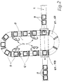
- ein Detail der Anlage nach
Figur 1 in vergrößerter Darstellung, schematisiert.
- Fig. 1:
- the schematic plan view of a processing and / or assembly system according to the invention;
- Fig. 2:
- a detail of the system of Figure 1 in an enlarged view, schematic.
Ein Hauptförderer 1 bildet auf einem ebenen Flur ein Oval und umschließt so eine Fläche 2. Diese Fläche 2 ist zugänglich über eine Treppe 3 und einen Tunnel 4. Der Hauptförderer 1 verbindet eine Reihe von automatischen Bearbeitungs- und/oder Montagemaschinen 51 bis 59 sowie eine Anzahl von Satellitenförderern 61 bis 68, an denen manuelle Arbeitsstationen 7 angeordnet sind. Die Satellitenförderer 61 bis 68 sind gleichfalls als auf ebenem Flur angeordnete Ovale ausgebildet, welche jeweils eine Fläche 8 umschließen. Der Hauptförderer 1 sowie die Satellitenförderer 61 bis 68 fördern Werkstückträger 9, die an der Montagemaschine 51 automatisch mit einer Grundausstattung von Material beschickt werden. Der Werkstückträger 9 mit dem von der Montagemaschine 51 geordnet aufgelegten, eventuell vorgefertigten und teilweise vormontierten Material wird vom Hauptförderer 1 zu einer ersten Werkstückübergabevorrichtung 101, welche den Satellitenförderer 61 mit dem Hauptförderer 1 verbindet, gefördert. Von der Werkstückübergabevorrichtung 101 wird entschieden, ob an den auf dem Werkstückträger 9 befindlichen Werkstücken solche Arbeitsoperationen erforderlich sind, die an Arbeitsstationen 7 des Satellitenförderers 61 durchgeführt werden. Diese Entscheidung kann durch eine an sich bekannte Codierung des Werkstückträgers 9 beim Aufliegen des Materials durch die Montagemaschine 51 ermöglicht werden. Ist eine Bearbeitung an den Arbeitsstationen 7 des Satellitenförderers 61 vorgesehen, dann wird der Werkstückträger 9 von einer Werkstückabnahmestation der Werkstückübergabevorrichtung 101 vom Hauptförderer 1 abgenommen, auf die jeweilige Arbeitshöhe des Satellitenförderers 61 gebracht und dort aufgesetzt. Der Satellitenförderer 61 bringt den Werkstückträger 9 zusammen mit dem aufliegenden Werkstück zu den aufeinanderfolgenden Arbeitsstationen 7, wobei der Satellitenförderer 61 je nach der Art dieser Arbeitsstationen 7 stetig oder schrittweise fördern kann. Dabei sind die Arbeitsplätze für die Arbeiter, welche die Arbeitsoperationen an den Arbeitsstationen 7 ausüben, innerhalb der Fläche 8 angeordnet, so daß ein räumlich abgeschlossener Arbeitsraum für das Arbeitsteam entsteht. Die für diese Arbeitsoperationen erforderlichen zusätzlichen Materialien und Hilfsstoffe werden durch eine Materialbeschickung 11 von außerhalb der Fläche 8 zugeführt und auf Materialträgern 12 abgelegt. Der Zugang zu den Flächen 8 kann über nicht dargestellte Treppen oder Tunnel oder ausschwenkbare Teile des Satellitenförderers erfolgen. Das Transportsystem der Satellitenförderer kann auch in einer solchen Höhe ausgeführt sein, daß es bequem überstiegen werden kann.A
Sind die auf dem Satellitenförderer 61 vorgesehenen Arbeitsoperationen abgeschlossen, dann erreicht der jeweilige Werkstückträger 9 wieder die Werkstückübergabevorrichtung 101, wo er auf das Niveau des Hauptförderers 1 gebracht und von einer Werkstückabsetzstation wieder auf den Hauptförderer 1 umgesetzt wird. Der Hauptförderer 1 führt den Werkstückträger 9 mit dem angearbeiteten Werkstück der automatischen Bearbeitungs- und/oder Montagemaschine 52 zur weiteren Bearbeitung zu. Nach erfolgter automatischer Bearbeitung, welches natürlich auch eine Montageoperation sein kann, wird der Werkstückträger 9 nun der Werkstückübergabevorrichtung 102 zugeführt, bei der sich im allgemeinen der Vorgang zur Übernahme auf den Satellitenförderer 62 in gleicher Weise wiederholt, wie dies für den Satellitenförderer 61 beschrieben ist. Wird jedoch an der Werkstückübergabeeinrichtung 102 festgestellt, daß für das aktuell vorliegende Werkstück die Arbeitsoperationen der an dem Satellitenförderer 61 angeordneten Arbeitsstationen 7 nicht erforderlich sind, indem z. B. ein bestimmtes Aggregat an dieses Werkstück nicht angefügt werden soll, dann wird der Werkstückträger 9 von der Werkstückübergabeeinrichtung 102 direkt auf den Hauptförderer 1 weitergeleitet, wo er dann auf die nächste, hier automatisierte Bearbeitungs- bzw. Montagemaschine 53 trifft.When the work operations provided on the
Die Bearbeitung bzw. Montage des Werkstückes, z. B. eines Verbrennungsmotors, setzt sich über die folgenden automatischen Bearbeitungs- und/oder Montagemaschinen 54 bis 59 sowie die Arbeitsstationen 7 innerhalb der Satellitenförderer 63 bis 68 fort. Dabei kann den automatischen Bearbeitungs- bzw. Montagemaschinen 51 bis 59 durch Materialbeschickungseinrichtungen 13 Material und Hilfsstoff zugeführt werden.The processing or assembly of the workpiece, for. B. an internal combustion engine continues through the following automatic processing and / or
Innerhalb der vom Hauptförderer 1 umschlossenen Fläche 2 sind Schaltschränke 14 für die Steuerung der Anlage insgesamt sowie für die automatischen Bearbeitungs- und/oder Montagemaschinen 51 bis 59 untergebracht. Ebenso ist innerhalb der Fläche 2 ein Wartungs- und Instandhaltungszentrum 15 für die Anlage vorgesehen.Within the
An der automatischen Montagemaschine 59 wird das fertig bearbeitete Werkstück, z. B. der fertig montierte Verbrennungsmotor, von dem Werkstückträger 8 abgenommen und aus der Anlage entnommen. Der Werkstückträger 8 läuft über den Hauptförderer 1 wieder bei der Bearbeitungs- und/oder Montagemaschine 51 in den Kreislauf der Anlage ein.On the
Die Erfindung ermöglicht eine Vielzahl von Ausführungsbeispielen. So kann die Anordnung von automatischen Bearbeitungs- bzw. Montagemaschinen und Satellitenförderern beliebig variiert werden. Der Hauptförderer und die Satellitenförderer können als Stetigförderer oder als Schrittförderer ausgelegt sein. Die Werkstückübergabevorrichtungen können, wie im weiter oben beschriebenen Ausführungsbeispiel dargelegt, mit jeweils einer Werkstückabnahmestation und einer Werkstückaufsetzstation versehen sein, so daß gleichzeitig ein Werkstück vom Hauptförderer abgenommen und ein anderes aufgesetzt wird. Sie können jedoch ebenso mit einer kombinierten Werkstückabnahme- und Aufsetzstation ausgerüstet sein, so daß nacheinander jeweils ein Werkstück vom Hauptförderer abgenommen und ein anderes aufgesetzt wird.The invention enables a large number of exemplary embodiments. The arrangement of automatic processing or assembly machines and satellite conveyors can be varied as required. The main conveyor and the satellite conveyors can be designed as continuous conveyors or as step conveyors. The workpiece transfer devices can, as explained in the exemplary embodiment described above, each be provided with a workpiece removal station and a workpiece placement station, so that at the same time one workpiece is removed from the main conveyor and another is placed on it. However, they can also be equipped with a combined workpiece removal and placement station, so that one workpiece is removed from the main conveyor and another is placed one after the other.
Es ist auch möglich, an einer Anlage einige Satellitenförderer mit einer Werkstückübergabevorrichtung mit jeweils getrennten Werkstückabnahme- und Werkstückaufsetzstationen und andere Satellitenförderer mit einer kombinierten Werkstückabnahme- und Aufsetzstation vorzusehen.It is also possible to have a few satellite conveyors on a system with a workpiece transfer device, each with separate workpiece removal and workpiece placement stations and to provide other satellite conveyors with a combined workpiece removal and placement station.
Die Anlage kann durch entsprechende Gestaltung der Innenflächen von Haupt- und Satellitenförderern gut an vorhandene Platzverhältnisse angepaßt werden. Der Hauptförderer kann auch so ausgeführt sein, daß lediglich eine Linie zugänglich ist, also keine Fläche von ihm umgrenzt ist und daß an dieser Linie die Satellitenförderer ein- oder beidseitig anschließen.The system can be adapted well to the available space by appropriately designing the interior surfaces of main and satellite conveyors. The main conveyor can also be designed in such a way that only one line is accessible, that is, no area is delimited by it, and that the satellite conveyors connect to this line on one or both sides.
Der besondere Vorteil der Erfindung besteht darin, daß mit einer Bearbeitungs- und/oder Montageanlage mit festliegender Konfiguration unterschiedlich lange Arbeitswege und damit unterschiedliche Arbeitsvolumina nebeneinander realisiert werden können. Die Anlage läßt sich dabei sehr kompakt anordnen, so daß nur eine relativ geringe Grundfläche erforderlich ist. Trotzdem werden für die an einer solchen Anlage arbeitenden Menschen gute Arbeitsbedingungen mit deutlicher Gruppenbildung geschaffen. Die Einstellbarkeit der Arbeitshöhe an den Satellitenförderern ermöglicht optimale ergonomische Arbeitsbedingungen. Der Einsatz einer solchen Anlage ist durch variable Besetzung der Satellitenförderer mit Arbeitskräften einfach auf unterschiedliche Kapazitäten einzurichten, wobei dann trotzdem eine gleichmäßige Arbeitsbelastung für die Arbeitskräfte sichergestellt ist. In der Anlage können die von den Satellitenförderern abgedeckten Arbeitsoperationen wahlweise ausgelassen werden. Innerhalb jeder der Satellitenförderer können fehlerhafte Werkstücke zur Behebung des Fehlers ein zweites Mal umlaufen, so daß keine fehlerhaften Werkstücke auf den Hauptförderer gelangen.The particular advantage of the invention is that with a processing and / or assembly system with a fixed configuration, work paths of different lengths and thus different work volumes can be realized side by side. The system can be arranged very compactly, so that only a relatively small footprint is required. Nevertheless, good working conditions with clear group formation are created for the people working on such a system. The adjustability of the working height on the satellite conveyors enables optimal ergonomic working conditions. The use of such a system can easily be set up for different capacities by means of variable staffing of the satellite conveyors, whereby an even workload for the workers is nevertheless ensured. The work operations covered by the satellite conveyors can optionally be omitted in the system. Defective workpieces can revolve a second time within each of the satellite conveyors in order to remedy the defect, so that no defective workpieces get onto the main conveyor.
Claims (16)
Applications Claiming Priority (2)
| Application Number | Priority Date | Filing Date | Title |
|---|---|---|---|
| DE19514206A DE19514206A1 (en) | 1995-04-15 | 1995-04-15 | Processing and / or assembly system |
| DE19514206 | 1995-04-15 |
Publications (3)
| Publication Number | Publication Date |
|---|---|
| EP0737543A2 true EP0737543A2 (en) | 1996-10-16 |
| EP0737543A3 EP0737543A3 (en) | 1997-10-29 |
| EP0737543B1 EP0737543B1 (en) | 2002-06-19 |
Family
ID=7759759
Family Applications (1)
| Application Number | Title | Priority Date | Filing Date |
|---|---|---|---|
| EP96105340A Expired - Lifetime EP0737543B1 (en) | 1995-04-15 | 1996-04-03 | Machining and/or assembling center |
Country Status (7)
| Country | Link |
|---|---|
| EP (1) | EP0737543B1 (en) |
| AT (1) | ATE219409T1 (en) |
| BR (1) | BR9601368A (en) |
| CZ (1) | CZ292142B6 (en) |
| DE (2) | DE19514206A1 (en) |
| ES (1) | ES2178686T3 (en) |
| PT (1) | PT737543E (en) |
Cited By (12)
| Publication number | Priority date | Publication date | Assignee | Title |
|---|---|---|---|---|
| WO1999037526A1 (en) * | 1998-01-26 | 1999-07-29 | Thyssen Krupp Industries Ag | Method for producing doors, hoods or single parts made of sheet metal in automotive bodyshells |
| WO2003074348A1 (en) * | 2002-03-01 | 2003-09-12 | Bayerische Motoren Werke Aktiengesellschaft | Assembly plant for assembling industrial products |
| WO2009047414A1 (en) * | 2007-10-10 | 2009-04-16 | Peugeot Citroën Automobiles SA | Method for extending an assembly hall of a motor vehicle manufacturing plant and associated assembly halls |
| WO2012128705A1 (en) * | 2011-03-21 | 2012-09-27 | Eton Ab | Conveyor work station |
| US8627558B2 (en) | 2007-12-05 | 2014-01-14 | Abb Research Ltd. | Production line and method for operating such |
| EP3214024A1 (en) * | 2016-03-01 | 2017-09-06 | EWAB Engineering AB | Autonomous conveyor system |
| CN108015543A (en) * | 2017-12-29 | 2018-05-11 | 安徽全柴动力股份有限公司 | A kind of built-in linear system system of engine piston connecting rod assembly |
| CN108515329A (en) * | 2018-06-12 | 2018-09-11 | 广东大唐永恒智能科技有限公司 | Auto bulb automatic setup system |
| CN109605026A (en) * | 2018-12-18 | 2019-04-12 | 昆山麦思创机械工业有限公司 | Assembling based on flexible connection detects integral type assembling line |
| CN109664115A (en) * | 2018-12-29 | 2019-04-23 | 天津市天森智能设备有限公司 | A kind of flexible manufacturing system |
| CN110834061A (en) * | 2019-12-09 | 2020-02-25 | 平湖市高嘉机械有限公司 | Multifunctional automatic oil removal online device |
| CN114981849A (en) * | 2019-11-13 | 2022-08-30 | 捷德货币技术有限责任公司 | Device and method for processing value documents |
Families Citing this family (3)
| Publication number | Priority date | Publication date | Assignee | Title |
|---|---|---|---|---|
| DE19752750A1 (en) | 1997-11-28 | 1999-06-10 | Hennecke Gmbh | Device for introducing and removing work stations running on a chain |
| DE20112576U1 (en) * | 2001-07-31 | 2002-10-31 | Kuka Schweissanlagen Gmbh | manufacturing plant |
| DE102021004658A1 (en) | 2021-09-14 | 2021-11-11 | Daimler Ag | System for the production of electric vehicles |
Citations (8)
| Publication number | Priority date | Publication date | Assignee | Title |
|---|---|---|---|---|
| DE2262210A1 (en) * | 1971-12-29 | 1973-07-12 | Seiko Instr & Electronics | AUTOMATIC TRANSPORT SYSTEM |
| JPS59209974A (en) * | 1983-05-13 | 1984-11-28 | Daifuku Co Ltd | Method of conveying engine by means of conveying line including test line |
| JPS6121869A (en) * | 1984-07-09 | 1986-01-30 | Mazda Motor Corp | Car assembly line |
| DE3540316A1 (en) * | 1985-11-13 | 1987-05-14 | Siemens Ag | MANUFACTURING SYSTEM FOR AUTOMATIC ASSEMBLY AND TESTING OF ELECTRONIC FLAT ASSEMBLIES |
| EP0419376A1 (en) * | 1989-09-22 | 1991-03-27 | Merlin Gerin | Production machine including a rapid-action device for feeding and positioning with a double pilgrim process and production system employing this type of machine |
| DE4100562A1 (en) * | 1990-01-17 | 1991-07-18 | Mazda Motor | METHOD FOR ASSEMBLING THE FRONT PANEL OF A VEHICLE BODY FOR MOTOR VEHICLES |
| EP0491448A1 (en) * | 1990-12-19 | 1992-06-24 | Siemens Aktiengesellschaft | Manufacturing system for part-assembled function units |
| DE4244351A1 (en) * | 1991-12-27 | 1993-07-01 | Mitsubishi Electric Corp | Automatic transport system for factory production line - has main loop rail with subsidiary loops connected by points, with controller to switch vehicles between loops |
Family Cites Families (4)
| Publication number | Priority date | Publication date | Assignee | Title |
|---|---|---|---|---|
| US5044541A (en) * | 1989-04-21 | 1991-09-03 | Nissan Motor Co., Ltd. | Method and apparatus for assembling vehicle body |
| DE69118499T2 (en) * | 1990-12-28 | 1996-11-07 | Mazda Motor | Method of assembling automobiles |
| DE9106962U1 (en) * | 1991-06-07 | 1992-10-08 | Altratec Montagesysteme Gmbh, 7141 Schwieberdingen, De | |
| DE9315721U1 (en) * | 1993-10-15 | 1995-02-16 | Altratec Montagesysteme | Transport route |
-
1995
- 1995-04-15 DE DE19514206A patent/DE19514206A1/en not_active Withdrawn
-
1996
- 1996-04-03 EP EP96105340A patent/EP0737543B1/en not_active Expired - Lifetime
- 1996-04-03 PT PT96105340T patent/PT737543E/en unknown
- 1996-04-03 AT AT96105340T patent/ATE219409T1/en not_active IP Right Cessation
- 1996-04-03 ES ES96105340T patent/ES2178686T3/en not_active Expired - Lifetime
- 1996-04-03 DE DE59609358T patent/DE59609358D1/en not_active Expired - Lifetime
- 1996-04-15 BR BR9601368A patent/BR9601368A/en not_active IP Right Cessation
- 1996-04-15 CZ CZ19961089A patent/CZ292142B6/en not_active IP Right Cessation
Patent Citations (8)
| Publication number | Priority date | Publication date | Assignee | Title |
|---|---|---|---|---|
| DE2262210A1 (en) * | 1971-12-29 | 1973-07-12 | Seiko Instr & Electronics | AUTOMATIC TRANSPORT SYSTEM |
| JPS59209974A (en) * | 1983-05-13 | 1984-11-28 | Daifuku Co Ltd | Method of conveying engine by means of conveying line including test line |
| JPS6121869A (en) * | 1984-07-09 | 1986-01-30 | Mazda Motor Corp | Car assembly line |
| DE3540316A1 (en) * | 1985-11-13 | 1987-05-14 | Siemens Ag | MANUFACTURING SYSTEM FOR AUTOMATIC ASSEMBLY AND TESTING OF ELECTRONIC FLAT ASSEMBLIES |
| EP0419376A1 (en) * | 1989-09-22 | 1991-03-27 | Merlin Gerin | Production machine including a rapid-action device for feeding and positioning with a double pilgrim process and production system employing this type of machine |
| DE4100562A1 (en) * | 1990-01-17 | 1991-07-18 | Mazda Motor | METHOD FOR ASSEMBLING THE FRONT PANEL OF A VEHICLE BODY FOR MOTOR VEHICLES |
| EP0491448A1 (en) * | 1990-12-19 | 1992-06-24 | Siemens Aktiengesellschaft | Manufacturing system for part-assembled function units |
| DE4244351A1 (en) * | 1991-12-27 | 1993-07-01 | Mitsubishi Electric Corp | Automatic transport system for factory production line - has main loop rail with subsidiary loops connected by points, with controller to switch vehicles between loops |
Non-Patent Citations (3)
| Title |
|---|
| PATENT ABSTRACTS OF JAPAN vol. 009, no. 080 (M-370), 10.April 1985 & JP 59 209974 A (DAIFUKU KIKO KK), 28.November 1984, * |
| PATENT ABSTRACTS OF JAPAN vol. 010, no. 171 (M-489), 17.Juni 1986 & JP 61 021869 A (MAZDA KK), 30.Januar 1986, * |
| TECHNISCHE RUNDSCHAU TRANSFER, Bd. 86, Nr. 36, 9.September 1994, Seiten 32-34, XP002038122 SCHAEFER F: "TRANSFERMODULE BASIS VON MONTAGEANLAGEN ELEKTROMECHANISCHE GERAETE FLEXIBEL UND WIRTSCHAFTLICH MONTIEREN" * |
Cited By (21)
| Publication number | Priority date | Publication date | Assignee | Title |
|---|---|---|---|---|
| WO1999037526A1 (en) * | 1998-01-26 | 1999-07-29 | Thyssen Krupp Industries Ag | Method for producing doors, hoods or single parts made of sheet metal in automotive bodyshells |
| WO2003074348A1 (en) * | 2002-03-01 | 2003-09-12 | Bayerische Motoren Werke Aktiengesellschaft | Assembly plant for assembling industrial products |
| CN100341740C (en) * | 2002-03-01 | 2007-10-10 | 宝马股份公司 | Assembly plant for assembling industrial products |
| CN101868400B (en) * | 2007-10-10 | 2012-10-03 | 标致·雪铁龙汽车公司 | Method for extending an assembly hall of a motor vehicle manufacturing plant and associated assembly halls |
| FR2922242A1 (en) * | 2007-10-10 | 2009-04-17 | Peugeot Citroen Automobiles Sa | METHOD FOR ENLARGING A WORKSHOP OF A FACTORY FOR MANUFACTURING AUTOMOTIVE VEHICLES AND ASSEMBLY WORKSHOPS |
| WO2009047414A1 (en) * | 2007-10-10 | 2009-04-16 | Peugeot Citroën Automobiles SA | Method for extending an assembly hall of a motor vehicle manufacturing plant and associated assembly halls |
| US8627558B2 (en) | 2007-12-05 | 2014-01-14 | Abb Research Ltd. | Production line and method for operating such |
| WO2012128705A1 (en) * | 2011-03-21 | 2012-09-27 | Eton Ab | Conveyor work station |
| US20190054587A1 (en) * | 2016-03-01 | 2019-02-21 | EWAB Engineering AB | Autonomous conveyor system |
| EP3214024A1 (en) * | 2016-03-01 | 2017-09-06 | EWAB Engineering AB | Autonomous conveyor system |
| WO2017148863A1 (en) * | 2016-03-01 | 2017-09-08 | EWAB Engineering AB | Autonomous conveyor system |
| US10618742B2 (en) * | 2016-03-01 | 2020-04-14 | EWAB Engineering AB | Autonomous conveyor system |
| CN108778963A (en) * | 2016-03-01 | 2018-11-09 | Ewab工程有限公司 | Autonomous conveyer system |
| CN108015543A (en) * | 2017-12-29 | 2018-05-11 | 安徽全柴动力股份有限公司 | A kind of built-in linear system system of engine piston connecting rod assembly |
| CN108015543B (en) * | 2017-12-29 | 2023-08-29 | 安徽全柴动力股份有限公司 | Built-in line system of engine piston connecting rod assembly |
| CN108515329A (en) * | 2018-06-12 | 2018-09-11 | 广东大唐永恒智能科技有限公司 | Auto bulb automatic setup system |
| CN108515329B (en) * | 2018-06-12 | 2023-10-31 | 广东大唐永恒智能科技有限公司 | Automatic assembling system for automobile head lamp |
| CN109605026A (en) * | 2018-12-18 | 2019-04-12 | 昆山麦思创机械工业有限公司 | Assembling based on flexible connection detects integral type assembling line |
| CN109664115A (en) * | 2018-12-29 | 2019-04-23 | 天津市天森智能设备有限公司 | A kind of flexible manufacturing system |
| CN114981849A (en) * | 2019-11-13 | 2022-08-30 | 捷德货币技术有限责任公司 | Device and method for processing value documents |
| CN110834061A (en) * | 2019-12-09 | 2020-02-25 | 平湖市高嘉机械有限公司 | Multifunctional automatic oil removal online device |
Also Published As
| Publication number | Publication date |
|---|---|
| CZ108996A3 (en) | 1997-09-17 |
| DE59609358D1 (en) | 2002-07-25 |
| PT737543E (en) | 2002-11-29 |
| EP0737543A3 (en) | 1997-10-29 |
| EP0737543B1 (en) | 2002-06-19 |
| CZ292142B6 (en) | 2003-08-13 |
| ES2178686T3 (en) | 2003-01-01 |
| DE19514206A1 (en) | 1996-10-17 |
| ATE219409T1 (en) | 2002-07-15 |
| BR9601368A (en) | 1998-01-13 |
Similar Documents
| Publication | Publication Date | Title |
|---|---|---|
| DE2760217C2 (en) | ||
| EP1601492B1 (en) | Manufacturing plant for parts, particularly vehicle body parts | |
| EP0737543B1 (en) | Machining and/or assembling center | |
| DE3409843C2 (en) | Method and system for producing workpieces consisting of several parts | |
| EP0203170B1 (en) | Flexible manufacturing system for the processing and production of multiple-component assemblies, in particular unfinished coachwork assemblies | |
| EP2842892B1 (en) | Concatenation system for overhead transfer devices | |
| EP1100715B1 (en) | Flexible workstation and operating method | |
| DE102004053503B4 (en) | Honing system with several workstations | |
| DE10112169B4 (en) | Chained manufacturing system for performing machining operations on parts | |
| DE19713860A1 (en) | Method and device for manufacturing complex workpieces | |
| DE4229067A1 (en) | Flexible transport system | |
| DE19505622A1 (en) | System for assembling motor vehicle bodies | |
| DE202017102155U1 (en) | manufacturing station | |
| WO2014124835A1 (en) | Transport device for a vehicle assembly installation | |
| DE2521787A1 (en) | ASSEMBLY TAPE SYSTEM | |
| DE60121941T2 (en) | MANUFACTURING METHOD AND MANUFACTURING SYSTEM | |
| DE102016001006A1 (en) | Plant, treatment module and method of treating objects | |
| DE3902063C2 (en) | ||
| DE3438268A1 (en) | DEVICE FOR PALLETIZING FLAT PARTS | |
| WO2007121697A1 (en) | Manufacturing system with interlinking machining stations via a high transfer module | |
| DE4033184C2 (en) | Circular racking system | |
| DE10064523A1 (en) | Plant for processing workpieces | |
| EP0245317B1 (en) | High-frequency welding installation | |
| DE4422380A1 (en) | Production system with robots for bodywork assemblies | |
| DE4124291C2 (en) | Device for the transport of piece goods, in particular components |
Legal Events
| Date | Code | Title | Description |
|---|---|---|---|
| PUAI | Public reference made under article 153(3) epc to a published international application that has entered the european phase |
Free format text: ORIGINAL CODE: 0009012 |
|
| AK | Designated contracting states |
Kind code of ref document: A2 Designated state(s): AT DE ES FR GB IT PT |
|
| PUAL | Search report despatched |
Free format text: ORIGINAL CODE: 0009013 |
|
| AK | Designated contracting states |
Kind code of ref document: A3 Designated state(s): AT DE ES FR GB IT PT |
|
| 17P | Request for examination filed |
Effective date: 19980128 |
|
| 17Q | First examination report despatched |
Effective date: 20010227 |
|
| GRAG | Despatch of communication of intention to grant |
Free format text: ORIGINAL CODE: EPIDOS AGRA |
|
| GRAG | Despatch of communication of intention to grant |
Free format text: ORIGINAL CODE: EPIDOS AGRA |
|
| GRAH | Despatch of communication of intention to grant a patent |
Free format text: ORIGINAL CODE: EPIDOS IGRA |
|
| GRAH | Despatch of communication of intention to grant a patent |
Free format text: ORIGINAL CODE: EPIDOS IGRA |
|
| GRAA | (expected) grant |
Free format text: ORIGINAL CODE: 0009210 |
|
| AK | Designated contracting states |
Kind code of ref document: B1 Designated state(s): AT DE ES FR GB IT PT |
|
| REF | Corresponds to: |
Ref document number: 219409 Country of ref document: AT Date of ref document: 20020715 Kind code of ref document: T |
|
| REG | Reference to a national code |
Ref country code: GB Ref legal event code: FG4D Free format text: NOT ENGLISH |
|
| REF | Corresponds to: |
Ref document number: 59609358 Country of ref document: DE Date of ref document: 20020725 |
|
| GBT | Gb: translation of ep patent filed (gb section 77(6)(a)/1977) |
Effective date: 20020721 |
|
| REG | Reference to a national code |
Ref country code: PT Ref legal event code: SC4A Free format text: AVAILABILITY OF NATIONAL TRANSLATION Effective date: 20020918 |
|
| ET | Fr: translation filed | ||
| REG | Reference to a national code |
Ref country code: ES Ref legal event code: FG2A Ref document number: 2178686 Country of ref document: ES Kind code of ref document: T3 |
|
| PLBE | No opposition filed within time limit |
Free format text: ORIGINAL CODE: 0009261 |
|
| STAA | Information on the status of an ep patent application or granted ep patent |
Free format text: STATUS: NO OPPOSITION FILED WITHIN TIME LIMIT |
|
| 26N | No opposition filed |
Effective date: 20030320 |
|
| REG | Reference to a national code |
Ref country code: GB Ref legal event code: 732E Free format text: REGISTERED BETWEEN 20090219 AND 20090225 |
|
| REG | Reference to a national code |
Ref country code: GB Ref legal event code: 732E Free format text: REGISTERED BETWEEN 20090305 AND 20090311 |
|
| PGFP | Annual fee paid to national office [announced via postgrant information from national office to epo] |
Ref country code: PT Payment date: 20090330 Year of fee payment: 14 |
|
| PGFP | Annual fee paid to national office [announced via postgrant information from national office to epo] |
Ref country code: ES Payment date: 20090508 Year of fee payment: 14 |
|
| PGFP | Annual fee paid to national office [announced via postgrant information from national office to epo] |
Ref country code: IT Payment date: 20090423 Year of fee payment: 14 Ref country code: AT Payment date: 20090415 Year of fee payment: 14 |
|
| REG | Reference to a national code |
Ref country code: GB Ref legal event code: 732E Free format text: REGISTERED BETWEEN 20091029 AND 20091104 |
|
| REG | Reference to a national code |
Ref country code: GB Ref legal event code: 732E Free format text: REGISTERED BETWEEN 20091105 AND 20091111 |
|
| PG25 | Lapsed in a contracting state [announced via postgrant information from national office to epo] |
Ref country code: AT Free format text: LAPSE BECAUSE OF NON-PAYMENT OF DUE FEES Effective date: 20100403 |
|
| PG25 | Lapsed in a contracting state [announced via postgrant information from national office to epo] |
Ref country code: PT Free format text: LAPSE BECAUSE OF NON-PAYMENT OF DUE FEES Effective date: 20101004 |
|
| PG25 | Lapsed in a contracting state [announced via postgrant information from national office to epo] |
Ref country code: IT Free format text: LAPSE BECAUSE OF NON-PAYMENT OF DUE FEES Effective date: 20100403 |
|
| REG | Reference to a national code |
Ref country code: DE Ref legal event code: R081 Ref document number: 59609358 Country of ref document: DE Owner name: GM GLOBAL TECHNOLOGY OPERATIONS LLC (N. D. GES, US Free format text: FORMER OWNER: GM GLOBAL TECHNOLOGY OPERATIONS, INC., DETROIT, MICH., US Effective date: 20110323 Ref country code: DE Ref legal event code: R081 Ref document number: 59609358 Country of ref document: DE Owner name: GM GLOBAL TECHNOLOGY OPERATIONS LLC (N. D. GES, US Free format text: FORMER OWNER: GM GLOBAL TECHNOLOGY OPERATIONS, INC., DETROIT, US Effective date: 20110323 |
|
| REG | Reference to a national code |
Ref country code: ES Ref legal event code: FD2A Effective date: 20110715 |
|
| PG25 | Lapsed in a contracting state [announced via postgrant information from national office to epo] |
Ref country code: ES Free format text: LAPSE BECAUSE OF NON-PAYMENT OF DUE FEES Effective date: 20110705 |
|
| PG25 | Lapsed in a contracting state [announced via postgrant information from national office to epo] |
Ref country code: ES Free format text: LAPSE BECAUSE OF NON-PAYMENT OF DUE FEES Effective date: 20100404 |
|
| PGFP | Annual fee paid to national office [announced via postgrant information from national office to epo] |
Ref country code: GB Payment date: 20120328 Year of fee payment: 17 |
|
| PGFP | Annual fee paid to national office [announced via postgrant information from national office to epo] |
Ref country code: DE Payment date: 20120419 Year of fee payment: 17 |
|
| PGFP | Annual fee paid to national office [announced via postgrant information from national office to epo] |
Ref country code: FR Payment date: 20120504 Year of fee payment: 17 |
|
| GBPC | Gb: european patent ceased through non-payment of renewal fee |
Effective date: 20130403 |
|
| PG25 | Lapsed in a contracting state [announced via postgrant information from national office to epo] |
Ref country code: GB Free format text: LAPSE BECAUSE OF NON-PAYMENT OF DUE FEES Effective date: 20130403 Ref country code: DE Free format text: LAPSE BECAUSE OF NON-PAYMENT OF DUE FEES Effective date: 20131101 |
|
| REG | Reference to a national code |
Ref country code: FR Ref legal event code: ST Effective date: 20131231 |
|
| REG | Reference to a national code |
Ref country code: DE Ref legal event code: R119 Ref document number: 59609358 Country of ref document: DE Effective date: 20131101 |
|
| PG25 | Lapsed in a contracting state [announced via postgrant information from national office to epo] |
Ref country code: FR Free format text: LAPSE BECAUSE OF NON-PAYMENT OF DUE FEES Effective date: 20130430 |