EP0737529B1 - Nietsetzwerkzeug - Google Patents
Nietsetzwerkzeug Download PDFInfo
- Publication number
- EP0737529B1 EP0737529B1 EP96302299A EP96302299A EP0737529B1 EP 0737529 B1 EP0737529 B1 EP 0737529B1 EP 96302299 A EP96302299 A EP 96302299A EP 96302299 A EP96302299 A EP 96302299A EP 0737529 B1 EP0737529 B1 EP 0737529B1
- Authority
- EP
- European Patent Office
- Prior art keywords
- rivet
- pulling
- assembly
- segments
- mandrel
- Prior art date
- Legal status (The legal status is an assumption and is not a legal conclusion. Google has not performed a legal analysis and makes no representation as to the accuracy of the status listed.)
- Expired - Lifetime
Links
- 238000000926 separation method Methods 0.000 claims 1
- 238000010276 construction Methods 0.000 description 5
- 238000003780 insertion Methods 0.000 description 1
- 230000037431 insertion Effects 0.000 description 1
- 229920001296 polysiloxane Polymers 0.000 description 1
- 230000000452 restraining effect Effects 0.000 description 1
- 230000000717 retained effect Effects 0.000 description 1
Images

Classifications
-
- B—PERFORMING OPERATIONS; TRANSPORTING
- B21—MECHANICAL METAL-WORKING WITHOUT ESSENTIALLY REMOVING MATERIAL; PUNCHING METAL
- B21J—FORGING; HAMMERING; PRESSING METAL; RIVETING; FORGE FURNACES
- B21J15/00—Riveting
- B21J15/10—Riveting machines
- B21J15/30—Particular elements, e.g. supports; Suspension equipment specially adapted for portable riveters
- B21J15/32—Devices for inserting or holding rivets in position with or without feeding arrangements
-
- B—PERFORMING OPERATIONS; TRANSPORTING
- B21—MECHANICAL METAL-WORKING WITHOUT ESSENTIALLY REMOVING MATERIAL; PUNCHING METAL
- B21J—FORGING; HAMMERING; PRESSING METAL; RIVETING; FORGE FURNACES
- B21J15/00—Riveting
- B21J15/10—Riveting machines
- B21J15/16—Drives for riveting machines; Transmission means therefor
- B21J15/20—Drives for riveting machines; Transmission means therefor operated by hydraulic or liquid pressure
-
- Y—GENERAL TAGGING OF NEW TECHNOLOGICAL DEVELOPMENTS; GENERAL TAGGING OF CROSS-SECTIONAL TECHNOLOGIES SPANNING OVER SEVERAL SECTIONS OF THE IPC; TECHNICAL SUBJECTS COVERED BY FORMER USPC CROSS-REFERENCE ART COLLECTIONS [XRACs] AND DIGESTS
- Y10—TECHNICAL SUBJECTS COVERED BY FORMER USPC
- Y10T—TECHNICAL SUBJECTS COVERED BY FORMER US CLASSIFICATION
- Y10T29/00—Metal working
- Y10T29/53—Means to assemble or disassemble
- Y10T29/53709—Overedge assembling means
- Y10T29/53717—Annular work
- Y10T29/53726—Annular work with second workpiece inside annular work one workpiece moved to shape the other
- Y10T29/5373—Annular work with second workpiece inside annular work one workpiece moved to shape the other comprising driver for snap-off-mandrel fastener; e.g., Pop [TM] riveter
- Y10T29/53739—Pneumatic- or fluid-actuated tool
- Y10T29/53743—Liquid
- Y10T29/53748—Liquid and gas
Definitions
- the present invention relates to a riveting tool for use in setting blind rivets of the type which comprise a tubular rivet having a head, and a mandrel which passes through the tubular rivet and comprises a setting head which engages an end face of the tubular rivet remote from its head and a pulling head which is pulled to move the mandrel relative to the rivet to set it.
- Such rivets are commonly referred to as "double headed rivets”.
- a tool for setting a double headed rivet requires a nose piece supporting a pulling assembly, adapted to grip the pulling head of the mandrel to pull the rivet to set the rivet, and an abutment assembly arranged to engage the head of the rivet during its setting. It is necessary that the abutment assembly is capable of moving into an open position to allow the passage of the pulling head of the mandrel past the abutment assembly to engage the pulling assembly and then into a closed position to provide an abutment to engage the head of the rivet.
- the abutment assembly comprises a plurality of abutment members extending generally axially of the nosepiece around the pulling assembly and movable between an open position, in which the pulling head of the mandrel may be passed through the abutment assembly to be engaged by the pulling assembly and a closed position in which the abutment members provide an abutment to engage the rivet head.
- the abutment members are moved radially between their open and closed positions by a sleeve which is moved axially of the tool by a pneumatic piston and cylinder arrangement.
- This piston and cylinder arrangement is actuated by a sensor which detects when a rivet has been positioned in the pulling assembly and then causes the abutment members to close.
- This construction is somewhat complex and expensive particularly in that two separate drive pistons are required.
- Another riveting tool for use with double headed rivets includes a pulling assembly arranged to grip the pulling head of a mandrel to set the rivet and an abutment assembly extending generally axially around the pulling assembly and movable between an open position, in which the pulling head of the mandrel may be passed through the abutment assembly to be engaged by the pulling assembly, and a closed position in which the abutment members provide an abutment to engage the rivet head.
- the abutment members are mounted for axial movement against spring pressure and comprise cam means which on such axial movement cause the abutment members to move from their open to their closed positions.
- the pulling assembly comprises a collet assembly comprising collet members having latches adapted to engage behind the head of a mandrel.
- a collet assembly comprising collet members having latches adapted to engage behind the head of a mandrel.
- the present invention provides a riveting tool for use in setting blind rivets which comprise a tubular rivet having a head and a mandrel which passes through the tubular rivet and comprises a setting head, which engages an end face of the rivet, and a pulling head which is pulled to move the mandrel relative to the rivet to set it.
- the tool includes a nosepiece, a pulling assembly, mounted in the nosepiece and arranged to grip the pulling head of a mandrel, which is attached to a piston for movement relative to the nosepiece to pull the mandrel to set the rivet, and an abutment assembly mounted in the nosepiece and arranged to engage the head of the rivet during its setting and comprising a plurality of abutment members extending generally axially of the nosepiece around the pulling assembly and movable between an open position, in which the pulling head of the mandrel may be passed through the abutment assembly to be engaged by the pulling assembly, and a closed position in which the abutment members provide an abutment to engage the rivet head.
- the abutment members are coupled to the pulling assembly for movement relative to the nosepiece after the rivet has been set and cam means are provided to open the abutment members.
- a new rivet is delivered in front of the abutment members for insertion therebetween during the return stroke of the piston.
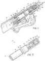
- the tool according to the invention is a tool for setting blind rivets of the "double headed" type, that is to say blind rivets as shown in Figure 1 which comprise a tubular rivet 2 having a head 4 and a mandrel 6 which passes through the rivet 2 and which has setting head 8 which engages an end face of the tubular rivet 2 remote from the head 4, and a pulling head 10. It will be understood that the rivet 2 is set by pulling the head 10 while restraining the rivet 2 by engagement of the rivet head 4.
- the tool comprises a housing 12 which is fixed to the body of a hydraulic driver (not shown).
- the housing shown cut away in Figure 1, comprises a generally cylindrical body which retains the elements of the pulling and supporting mechanism of the tool.
- the housing 12 includes a slot 14 through which a feeder mechanism 16 provides a continuous supply of rivets 2.
- the feeder mechanism 16 is described in detail in my co-pending application serial no. (Docket S4833).
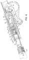
- a pulling collet assembly 17, shown in Figure 2, is disposed within the housing 12.
- the collet assembly includes a rear collet member 18 coupled to a piston 19 and a forward collet member 20 which are coupled at the screw threads 22.
- a tube 23 through the centre of the assembly provides for vacuum withdrawal of the broken mandrel in the normal manner.
- Contained within the forward collet member 20 are a coil spring 24, a washer 26 and a plurality of pulling segments 28, of which two are illustrated.
- Each pulling segment includes a forward conical surface 30 and a rearwardly facing latch surface 32, the latch surface being adapted to engage behind the head 10 of the mandrel 6.
- the pulling segments are biased forwardly by the spring 24 so that the conical surfaces 30 are urged against a corresponding internal conical surface 34 at the front end of the forward collet member 20. This biases the segments 28 into a closed or latched position.
- An aperture 36 is provided at the front end of the forward collet member 20, the aperture being sized to receive the head 10 of the mandrel 6.
- a plurality of support segments 38 are provided which surround the collet assembly and are retained by the housing 12.
- the forward end of each support segment 38 ends in an external face 40 which may be flat or, if desired, may be somewhat concave to better accommodate the head 4 of the rivet 2 when the rivet is in place.
- the rearward end of each support segment 38 comprises an outwardly extending cam 42 and an inwardly extending tooth 44.
- the outwardly extending cam 42 engages an inwardly extending cam 46 on the inside surface of the housing 12.
- the teeth 44 rest against a resilient washer 54 located in groove 50 so that the cam surfaces 42 and 46 initially prevent the support segments from moving when the collet assembly is retracted.
- the inwardly extending tooth 44 co-operates with grooves 48 and 50 and flange 52 formed on the outer surface of the rear collet member 18 in a manner which will now be described.
- the setting tool as shown in Figure 1 is configured to set the rivet 2 in a workpiece which is not shown.
- the setting tool is operable by means of a conventional hydraulic driver, for example of the type shown in U.S. Patent 4,598,571, which culminates in a hydraulically operated piston.
- the piston is coupled to the rear end of the rear collet member 18.
- the hydraulic piston is operated and moves rearwardly, thus drawing with it the collet assembly. Since the cam surface 42 of the support segments 38 is held outwardly in engagement with cam surface 44 by means of the silicone washer 54 in groove 50 and by the external surface of the rear collet member 18 between the two grooves 48 and 50, the support segments 38 remain stationary during the initial movement of the collet assembly. Accordingly, the mandrel 6 is pulled relative to the rivet 2 until the setting head 8 sets the rivet and the mandrel 6 breaks in conventional manner.
- the collet assembly continues to move rearwardly until the tooth 44 of the support segments 38 becomes aligned with the groove 48 as shown in Figure 3. Due to the cams 42 and 46, the rear end of the support segments 38 move radially inward as the teeth 44 enter the groove 48.
- the enlarged diameter of the flange 52 is accommodated by an enlarged inner-diameter 56 on the inner surface of the support segments immediately forward of the teeth 44.
- the flange 52 is now engaged with the facing surface 58 of the teeth 44.
- the cams 42 and 44 disengage and continued rearward motion of the collet assembly drives the support segments rearwardly so that they enter fully within the housing 12 and are moved behind the rearward end of the slot 14 in housing 12.
- the feeder mechanism 16 operates to enter the housing 12 and presents a new rivet in front of the support segments 38.
- the forward motion of the collet assembly begins, producing the position illustrated in Figure 4.
- the support segments move forward past a head 10 of the mandrel until they encounter the flange or head 4 of the rivet.
- Continued forward motion of the collet assembly lifts the teeth 44 out of the groove 48 and the collet assembly moves forward relative to the support segments.
- the spring 24 When the pulling segments 28 reach the head 10, the spring 24 is compressed, allowing the pulling segments to move back relative to forward collet member 20. The pulling segments open, admitting the head 10. As soon as the head passes far enough into the pulling segments, the spring 24 and washer 26 drive the segments forward against the internal surface 34 of member 20 so that the latching surfaces 32 engage behind the head 10.
- the stop means formed by cam 46 could be provided by a spring-biased stop ring mounted in the housing.
- a suitably positioned cam on the collet assembly could then be used to drive the stop ring out of the path of the support segments after breakage of the mandrel.
- This construction also enables the use of a single drive piston to reciprocate both the collet assembly and the support segments.
- this tool is comparatively simple and inexpensive. It is further readily adapted to use with various types of automatic feeders such as that illustrated in the previously identified co-pending application so that the tool can be operated by hand or machine to rapidly present and set double headed rivets of the type described.
Landscapes
- Engineering & Computer Science (AREA)
- Mechanical Engineering (AREA)
- Insertion Pins And Rivets (AREA)
Claims (7)
- Nietsetzwerkzeug für Blindniete mit vergrößertem Ziehkopf auf einem Schaft zum Setzen der Niete, umfassend:ein Gehäuse (12);eine Hülsenbaugruppe (17), eingebaut zum Hin- und Herbewegen im Gehäuse wobei die Hülsenbaugruppe enthält:Ziehsegmente (28), die den Schaftziehkopf (10) zum Ziehen des Schaftes (6) erfassen, um das Niet zu setzen und den Schaft während der Rückwärtsbewegung der Hülsenbaugruppe (17) zu brechen; undein Rohr (23) zum Entfernen des gebrochenen Schaftes durch die Hülsenbaugruppe;mehrere Stützsegmente (38) in dem Gehäuse, um die Hülsenbaugruppe herum zum Erfassen des Niets;Anhaltemittel an dem Gehäuse (12) zur Verhinderung der Bewegung der Stützsegmente (38) während des Nietsetzens;Mittel zum Lösen der Anhaltemittel nach dem Brechen des Schaftes (6);Antriebsmittel an der Hülsenbaugruppe (17), die mit den Stützsegmenten in Eingriff bringbar sind zum Zurückziehen der Stützsegmente (38) nach Lösung der Anhaltemittel, um das Heranbringen eines Niets vor die Stützsegmente (38) zuzulassen, und zum Bewegen der Stützsegmente in Eingriff mit einem Niet und der Ziehsegmente (28) in Eingriff mit dem Schaftziehkopf bei der Vorwärtsbewegung der Hülsenbaugruppe (17).
- Setzwerkzeug nach Anspruch 1, enthaltend einen Kolben (19) zum Ziehen der Hülsenbaugruppe (17) für das Nietsetzen und für das Hin- und Herbewegen der Hülsenbaugruppe und der Stützsegmente (38) durch eine hintere Position, die die Zufuhr eines Niets vor die Stützsegmente erlaubt, und in eine vordere Position, in denen die Stützsegmente das Niet erfassen und die Ziehsegmente (28) den vergrößerten Ziehkopf erfassen.
- Nietsetzwerkzeug nach Anspruch 1, wobei das Antriebsmittel so auf der Hülsenbaugruppe (17) angeordnet ist, daß es die Stützsegmente (38) unmittelbar nach der Betätigung der Lösemittel erfaßt.
- Nietsetzwerkzeug nach Anspruch 1, wobei das Anhaltemittel eine erste Schulter (46) an dem Gehäuse und eine Anschlagschulter (42) an jedem der Stützsegmente (38) umfaßt.
- Nietsetzwerkzeug nach Anspruch 4, wobei die Lösemittel eine Ausnehmung (48) in der Hülsenbaugruppe umfassen, wobei die Ausnehmung die radiale Trennung der ersten Schulter (46) und der Anschlagschulter (42) erlaubt.
- Nietsetzwerkzeug nach Anspruch 5, wobei die Antriebsmittel nahe der Ausnehmung (48) angeordnet sind.
- Nietsetzwerkzeug für Blindnieten mit einem vergrößerten Ziehkopf auf dem Schaft zum Setzen des Niets, umfassend:ein Gehäuse (12);einen Kolben (19), der für Hin- und Herbewegung in dem Gehäuse montiert ist;eine Ziehbaugruppe (17), die mit dem Kolben gekoppelt ist, wobei die Ziehbaugruppe umfaßtein röhrenförmiges Element, das sich nach vorne von dem Kolben erstreckt und einen zylindrischen Abschnitt, einen Abschnitt verringerten Durchmessers und einen Flanschabschnitt (52) aufweist; undeine Hülse zur Aufnahme des vergrößerten Schaftziehkopfes, der in Vorwärtsrichtung des Flanschabschnittes angeordnet ist; undeine Stützbaugruppe, die mehrere Stützsegmente (38) aufweist, die die Ziehbaugruppe umgeben, wobei jedes der Segmente ein vorderes Ende zum Erfassen eines Nietflansches während des Setzens und ein hinteres Ende aufweist, das einen nach innen ragenden Zahn oder Finger (44) und eine nach außen erstreckte Schulter (42) aufweist;wobei das Gehäuse eine nach innen erstreckte Schulter (46) aufweist, die so angeordnet ist, daß sie an die nach außen erstreckte Schulter (42) anschlägt und die Stützbaugruppe während des Setzens gegen den Nietflansch hält, wobei die erste und zweite Schulter zusammenwirken, um die Finger (44) in den Abschnitt verringerten Durchmessers zu bewegen, um die Anschlagsegmente nach dem Setzen zu öffnen und das Zurückziehen der Anschlagbaugruppe durch Eingriff des Flanschabschnittes (52) mit den Fingern (44) zu erlauben.
Applications Claiming Priority (2)
| Application Number | Priority Date | Filing Date | Title |
|---|---|---|---|
| US421590 | 1995-04-12 | ||
| US08/421,590 US5519927A (en) | 1995-04-12 | 1995-04-12 | Rivet setting tool |
Publications (2)
| Publication Number | Publication Date |
|---|---|
| EP0737529A1 EP0737529A1 (de) | 1996-10-16 |
| EP0737529B1 true EP0737529B1 (de) | 1999-09-29 |
Family
ID=23671201
Family Applications (1)
| Application Number | Title | Priority Date | Filing Date |
|---|---|---|---|
| EP96302299A Expired - Lifetime EP0737529B1 (de) | 1995-04-12 | 1996-04-01 | Nietsetzwerkzeug |
Country Status (4)
| Country | Link |
|---|---|
| US (1) | US5519927A (de) |
| EP (1) | EP0737529B1 (de) |
| JP (1) | JPH08318344A (de) |
| DE (1) | DE69604437T2 (de) |
Families Citing this family (6)
| Publication number | Priority date | Publication date | Assignee | Title |
|---|---|---|---|---|
| US6014801A (en) * | 1998-04-29 | 2000-01-18 | Huck International | Swage fastening tool |
| US6519997B2 (en) | 2001-01-03 | 2003-02-18 | Allfast Fastening Systems, Inc. | Rivet gun |
| USD503327S1 (en) * | 2003-03-27 | 2005-03-29 | Newfrey Llc | Blind rivet setting tool |
| KR101776483B1 (ko) * | 2016-04-05 | 2017-09-08 | 현대자동차주식회사 | 블라인드리벳 장착장치 |
| CN106955964B (zh) * | 2017-03-28 | 2019-01-01 | 北京新能源汽车股份有限公司 | 铆钉安装工具 |
| CN111396428A (zh) * | 2020-04-14 | 2020-07-10 | 眉山中车紧固件科技有限公司 | 一种单槽单面紧固件及其安装方法 |
Family Cites Families (9)
| Publication number | Priority date | Publication date | Assignee | Title |
|---|---|---|---|---|
| DE6948952U (de) * | 1968-12-20 | 1970-09-03 | Visser Andreas Haye | Selbstbohrender blindniet |
| US3886783A (en) * | 1974-07-25 | 1975-06-03 | Richard F Hirsch | Automatic loading blind riveter |
| US4630460A (en) * | 1986-02-14 | 1986-12-23 | Usm Corporation | Fastener-setting tool |
| US4628722A (en) * | 1986-02-14 | 1986-12-16 | Usm Corporation | Setting tool for rivet with pull-headed mandrel |
| US4811881A (en) * | 1987-11-20 | 1989-03-14 | Phillips Plastics Corporation | Apparatus for supplying and installing plastic expansion rivets |
| JPH0441037A (ja) * | 1990-06-05 | 1992-02-12 | Oputo Eng Kk | 連発リベッター |
| DE4023963A1 (de) * | 1990-07-27 | 1992-01-30 | Tucker Gmbh Bostik | Blindnietsetzwerkzeug |
| GB2248573A (en) * | 1990-10-05 | 1992-04-15 | Avdel Systems Ltd | Nosepiece assembly |
| GB9218463D0 (en) * | 1992-08-29 | 1992-10-14 | Emhart Inc | Rivet setting tool |
-
1995
- 1995-04-12 US US08/421,590 patent/US5519927A/en not_active Expired - Fee Related
-
1996
- 1996-04-01 EP EP96302299A patent/EP0737529B1/de not_active Expired - Lifetime
- 1996-04-01 DE DE69604437T patent/DE69604437T2/de not_active Expired - Fee Related
- 1996-04-09 JP JP8086732A patent/JPH08318344A/ja active Pending
Also Published As
| Publication number | Publication date |
|---|---|
| JPH08318344A (ja) | 1996-12-03 |
| US5519927A (en) | 1996-05-28 |
| DE69604437T2 (de) | 2000-02-24 |
| DE69604437D1 (de) | 1999-11-04 |
| EP0737529A1 (de) | 1996-10-16 |
Similar Documents
| Publication | Publication Date | Title |
|---|---|---|
| JP4694844B2 (ja) | 連結ネジを打ち込むためのオートフィード式スクリュードライバー | |
| EP0043217B1 (de) | Befestiger-Setzwerkzeug | |
| EP0586134B1 (de) | Nietwerkzeug | |
| TWI572425B (zh) | 盲鉚釘緊固工具及浮動件 | |
| US20100275424A1 (en) | Blind Rivet Fastening Device | |
| EP0737529B1 (de) | Nietsetzwerkzeug | |
| US6163945A (en) | Broken piece collecting assembly for fastener setting tool | |
| JPH02502360A (ja) | 火薬‐作動留め具打込み工具 | |
| CA2509001A1 (en) | Blind bolt installation tool | |
| EP0512806A1 (de) | Nietwerkzeug mit versetztem Ansatz und mit Löseeinrichtung für die Klemmbacken | |
| AU2002225173B2 (en) | Fastener installation tool including fastener-parts collection means | |
| EP0479513B1 (de) | Werkzeugnase zum Setzen von Blindnieten | |
| US4979279A (en) | Fastener installation tool apparatus | |
| US3657915A (en) | Automatic rear feeder for blind rivets | |
| AU749928B2 (en) | Riveting apparatus | |
| US5640758A (en) | Component feeder with reciprocal and rotatable magazine | |
| EP1606069B1 (de) | Versetzte nasenanorndung mit verbessertem deflektor und verbesserten schutzanordnungen | |
| JP2022532986A (ja) | ファスナー装着ツール | |
| JPS61206541A (ja) | ブラインドリベツト締め工具 | |
| US5788140A (en) | Device for driving inserts into pieces of sheet metal | |
| GB2306368A (en) | Rivet setting tool | |
| JPH04210333A (ja) | シール供給装置 | |
| JPS639126B2 (de) | ||
| JPH05261466A (ja) | ブラインドリベットかしめ機 | |
| GB2070520A (en) | Propelling pencil |
Legal Events
| Date | Code | Title | Description |
|---|---|---|---|
| PUAI | Public reference made under article 153(3) epc to a published international application that has entered the european phase |
Free format text: ORIGINAL CODE: 0009012 |
|
| AK | Designated contracting states |
Kind code of ref document: A1 Designated state(s): DE FR GB |
|
| 17P | Request for examination filed |
Effective date: 19970402 |
|
| GRAG | Despatch of communication of intention to grant |
Free format text: ORIGINAL CODE: EPIDOS AGRA |
|
| GRAG | Despatch of communication of intention to grant |
Free format text: ORIGINAL CODE: EPIDOS AGRA |
|
| 17Q | First examination report despatched |
Effective date: 19981221 |
|
| GRAG | Despatch of communication of intention to grant |
Free format text: ORIGINAL CODE: EPIDOS AGRA |
|
| GRAH | Despatch of communication of intention to grant a patent |
Free format text: ORIGINAL CODE: EPIDOS IGRA |
|
| GRAH | Despatch of communication of intention to grant a patent |
Free format text: ORIGINAL CODE: EPIDOS IGRA |
|
| GRAA | (expected) grant |
Free format text: ORIGINAL CODE: 0009210 |
|
| AK | Designated contracting states |
Kind code of ref document: B1 Designated state(s): DE FR GB |
|
| REF | Corresponds to: |
Ref document number: 69604437 Country of ref document: DE Date of ref document: 19991104 |
|
| ET | Fr: translation filed | ||
| PLBE | No opposition filed within time limit |
Free format text: ORIGINAL CODE: 0009261 |
|
| STAA | Information on the status of an ep patent application or granted ep patent |
Free format text: STATUS: NO OPPOSITION FILED WITHIN TIME LIMIT |
|
| 26N | No opposition filed | ||
| REG | Reference to a national code |
Ref country code: GB Ref legal event code: IF02 |
|
| PGFP | Annual fee paid to national office [announced via postgrant information from national office to epo] |
Ref country code: GB Payment date: 20050323 Year of fee payment: 10 |
|
| PGFP | Annual fee paid to national office [announced via postgrant information from national office to epo] |
Ref country code: FR Payment date: 20050418 Year of fee payment: 10 |
|
| PG25 | Lapsed in a contracting state [announced via postgrant information from national office to epo] |
Ref country code: GB Free format text: LAPSE BECAUSE OF NON-PAYMENT OF DUE FEES Effective date: 20060401 |
|
| PGFP | Annual fee paid to national office [announced via postgrant information from national office to epo] |
Ref country code: DE Payment date: 20060531 Year of fee payment: 11 |
|
| GBPC | Gb: european patent ceased through non-payment of renewal fee |
Effective date: 20060401 |
|
| REG | Reference to a national code |
Ref country code: FR Ref legal event code: CD |
|
| REG | Reference to a national code |
Ref country code: FR Ref legal event code: ST Effective date: 20061230 |
|
| PG25 | Lapsed in a contracting state [announced via postgrant information from national office to epo] |
Ref country code: DE Free format text: LAPSE BECAUSE OF NON-PAYMENT OF DUE FEES Effective date: 20071101 |
|
| PG25 | Lapsed in a contracting state [announced via postgrant information from national office to epo] |
Ref country code: FR Free format text: LAPSE BECAUSE OF NON-PAYMENT OF DUE FEES Effective date: 20060502 |