EP0737524B1 - Kühlkammer für Walzprodukte - Google Patents
Kühlkammer für Walzprodukte Download PDFInfo
- Publication number
- EP0737524B1 EP0737524B1 EP96104307A EP96104307A EP0737524B1 EP 0737524 B1 EP0737524 B1 EP 0737524B1 EP 96104307 A EP96104307 A EP 96104307A EP 96104307 A EP96104307 A EP 96104307A EP 0737524 B1 EP0737524 B1 EP 0737524B1
- Authority
- EP
- European Patent Office
- Prior art keywords
- cooling chamber
- slider
- taper
- cooling
- downstream
- Prior art date
- Legal status (The legal status is an assumption and is not a legal conclusion. Google has not performed a legal analysis and makes no representation as to the accuracy of the status listed.)
- Expired - Lifetime
Links
- 238000001816 cooling Methods 0.000 title claims abstract description 103
- 239000012809 cooling fluid Substances 0.000 claims abstract description 35
- 239000012530 fluid Substances 0.000 claims abstract description 21
- 238000011144 upstream manufacturing Methods 0.000 claims abstract description 17
- 238000005096 rolling process Methods 0.000 claims abstract description 5
- XLYOFNOQVPJJNP-UHFFFAOYSA-N water Substances O XLYOFNOQVPJJNP-UHFFFAOYSA-N 0.000 claims description 19
- 238000004140 cleaning Methods 0.000 claims description 4
- 230000008878 coupling Effects 0.000 claims description 3
- 238000010168 coupling process Methods 0.000 claims description 3
- 238000005859 coupling reaction Methods 0.000 claims description 3
- 238000012423 maintenance Methods 0.000 claims description 3
- 238000007789 sealing Methods 0.000 claims description 3
- 230000009471 action Effects 0.000 description 4
- 239000000498 cooling water Substances 0.000 description 4
- 230000001133 acceleration Effects 0.000 description 3
- 238000005260 corrosion Methods 0.000 description 3
- 230000007797 corrosion Effects 0.000 description 3
- 238000000034 method Methods 0.000 description 3
- 239000000110 cooling liquid Substances 0.000 description 2
- 230000000694 effects Effects 0.000 description 2
- 230000002035 prolonged effect Effects 0.000 description 2
- 230000009467 reduction Effects 0.000 description 2
- 230000001419 dependent effect Effects 0.000 description 1
- 238000010586 diagram Methods 0.000 description 1
- 230000001939 inductive effect Effects 0.000 description 1
- 238000009434 installation Methods 0.000 description 1
- 230000013011 mating Effects 0.000 description 1
- 238000012856 packing Methods 0.000 description 1
- 230000008569 process Effects 0.000 description 1
- 238000010791 quenching Methods 0.000 description 1
- 239000011150 reinforced concrete Substances 0.000 description 1
- 230000003014 reinforcing effect Effects 0.000 description 1
- 238000007669 thermal treatment Methods 0.000 description 1
Images


Classifications
-
- C—CHEMISTRY; METALLURGY
- C21—METALLURGY OF IRON
- C21D—MODIFYING THE PHYSICAL STRUCTURE OF FERROUS METALS; GENERAL DEVICES FOR HEAT TREATMENT OF FERROUS OR NON-FERROUS METALS OR ALLOYS; MAKING METAL MALLEABLE, e.g. BY DECARBURISATION OR TEMPERING
- C21D9/00—Heat treatment, e.g. annealing, hardening, quenching or tempering, adapted for particular articles; Furnaces therefor
- C21D9/52—Heat treatment, e.g. annealing, hardening, quenching or tempering, adapted for particular articles; Furnaces therefor for wires; for strips ; for rods of unlimited length
- C21D9/54—Furnaces for treating strips or wire
- C21D9/56—Continuous furnaces for strip or wire
- C21D9/573—Continuous furnaces for strip or wire with cooling
- C21D9/5732—Continuous furnaces for strip or wire with cooling of wires; of rods
-
- B—PERFORMING OPERATIONS; TRANSPORTING
- B21—MECHANICAL METAL-WORKING WITHOUT ESSENTIALLY REMOVING MATERIAL; PUNCHING METAL
- B21B—ROLLING OF METAL
- B21B45/00—Devices for surface or other treatment of work, specially combined with or arranged in, or specially adapted for use in connection with, metal-rolling mills
- B21B45/02—Devices for surface or other treatment of work, specially combined with or arranged in, or specially adapted for use in connection with, metal-rolling mills for lubricating, cooling, or cleaning
- B21B45/0203—Cooling
- B21B45/0209—Cooling devices, e.g. using gaseous coolants
- B21B45/0215—Cooling devices, e.g. using gaseous coolants using liquid coolants, e.g. for sections, for tubes
-
- B—PERFORMING OPERATIONS; TRANSPORTING
- B21—MECHANICAL METAL-WORKING WITHOUT ESSENTIALLY REMOVING MATERIAL; PUNCHING METAL
- B21B—ROLLING OF METAL
- B21B45/00—Devices for surface or other treatment of work, specially combined with or arranged in, or specially adapted for use in connection with, metal-rolling mills
- B21B45/02—Devices for surface or other treatment of work, specially combined with or arranged in, or specially adapted for use in connection with, metal-rolling mills for lubricating, cooling, or cleaning
- B21B45/0203—Cooling
- B21B45/0209—Cooling devices, e.g. using gaseous coolants
- B21B45/0215—Cooling devices, e.g. using gaseous coolants using liquid coolants, e.g. for sections, for tubes
- B21B45/0224—Cooling devices, e.g. using gaseous coolants using liquid coolants, e.g. for sections, for tubes for wire, rods, rounds, bars
Definitions
- This invention concerns a cooling chamber for rolled products, as set forth in the main claim.
- the cooling chamber according to the invention is installed in rolling lines downstream of the last finishing stand so as to quench the rolled product and/or between the single finishing stands to cool the rolled product passing through and to keep it at the desired temperature.
- the cooling chamber according to the invention enables the rolled product passing through to undergo a thermal treatment so as to provide the required physical and mechanical properties.
- the cooling chamber according to the invention is employed advantageously, but not only, to cool round reinforcing bars used in reinforced concrete.
- cooling chambers which contain an axial through bore, within which the rolled product runs axially and cooperates with a cooling fluid under pressure, which is generally water delivered into the cooling chamber.
- the cooling fluid in the cooling chambers of the state of the art can run in the same direction as and/or in the opposite direction to the rolled product so as to achieve the most intimate contact with the rolled product in order to cool the latter as quickly and evenly as possible.
- One embodiment arranges to deliver the cooling fluid into the cooling chamber through a plurality of radial holes located at regular intervals in the circumference of the chamber.
- the cooling chamber includes a casing closed upstream by an axially bored slider and downstream by a flange containing an axial tapered bore coaxial with the slider.
- the head of the slider has a truncated-cone conformation which cooperates with the tapered bore of the flange to define an annular hole for the passage of the cooling fluid, which enters the casing through a radial hole in the casing.
- the width of the annular hole can be varied by positioning the slider longitudinally.
- the present applicants have designed, embodied and tested this invention and have improved the geometric conformation of the components of the cooling chamber so as to overcome one or more of the shortcomings of the state of the art and to achieve further advantages such as, above all, a great reduction of the rate of flow of the required cooling fluid.
- the cooling chamber according to the invention is shaped structurally to maximise the efficiency of the cooling action on the rolled stock passing through.
- downstream segment of the slider within the cooling chamber has a first segment inclined in relation to the longitudinal axis of the chamber and followed by a first horizontal segment, which in turn is followed by a second inclined segment and by a second horizontal segment.
- This configuration causes a first acceleration of the cooling water in the direction of feed of the rolled stock passing through, and this acceleration is followed by a phase of parallelisation of the fluid streams at the position adjacent to the sidewall of the slider and then by a further acceleration substantially at the outlet of the rolled stock from the slider.
- the upstream segment of the slider has the outer walls of its inlet diverging in the downstream direction; in an analogous manner the outlet of the slider, or of a possible cooling tube associated axially and lengthwise with the slider, has its inner sidewalls flared in the downstream direction.
- this configuration enables the water leaving the upstream cooling chamber to be deviated and to be prevented from entering the downstream cooling chamber.
- the threaded portions coupling the slider to the outer casing are located at a position retracted from the cavity containing the cooling liquid and are protected by packings to prevent the wear and corrosion of those portions due to continuous and prolonged contact with the water.
- a feature of the cooling chamber according to a further preferred embodiment of the invention is that the feed of the water into the containing cavity takes place at a tangent to the sidewall of that cavity, thus leading to a circulation of the water which improves the efficiency of the cooling, given an equal rate of flow of water, or else makes possible the use of lower rates of flow of water, given an equal degree of cooling.
- the cooling chamber according to a further preferred embodiment of the invention has its casing capable of being easily and readily detached from the base, thus assisting the operations of cleaning, maintenance and any replacement of its inner components.
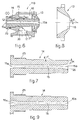
- the cooling chamber according to the invention is shown with some preferred embodiments in the attached tables, which are given as non-restrictive examples as follows:-
- the purpose of this invention is to provide a cooling chamber 10 for installation upstream and/or downstream of the finishing stands of a rolling line so as to cool quickly to the required temperature the rolled product passing through.
- the cooling chamber 10 enables the consumption of cooling fluid to be reduced by at least 30% or more as compared to the cooling chambers of the state of the art and at the same time ensures an even and constant cooling of the whole rolled product.
- cooling chamber 10 With the cooling chamber 10 according to the invention it is possible to regulate continuously and very accurately the rate of flow of the cooling fluid and thus to control properly the cooling process which the rolled product undergoes when passing through.
- the flow of cooling fluid in the cooling chamber 10 according to the invention is in the same direction as that of the feed of the rolled product, thus achieving the twofold effects that the flow of cooling fluid transmits to the rolled product an axial thrust which assists the sliding thereof and that the forward movement of the rolled product draws the cooling fluid and improves its outflow.
- the cooling chamber 10 has a special geometric configuration, which causes the fluid streams to follow trajectories that improve the heat exchange with the advancing rolled product with a resulting reduction of the overall consumption of cooling fluid.
- the cooling chamber 10 includes a casing 11 comprising an axial sliding seating 12, in which is positioned a slider 14 able to move longitudinally in a continuous manner and containing a through axial bore 15 through which the rolled product is fed.
- the casing 11 is closed at its downstream end by a flange 13, the through bore 16 of which is coaxial with the bore 15 of the slider 14 and is suitably shaped to cooperate with the head of the slider 14; the flange 13 defines together with the casing 11 a cavity 18 for circulation of cooling fluid.
- the cavity 18 cooperates with a lateral opening 17 for entry of cooling fluid fed under pressure by a suitable external source.
- the lateral opening 17 is positioned on a plane perpendicular to the longitudinal axis of the circulation cavity 18.
- the lateral opening 17 is radial to the circulation cavity 18.
- the lateral opening 17 is at a tangent to the inner wall of the circulation cavity 18 of the casing 11, thus inducing a circulation of the cooling water which improves considerably the cooling of the rolled stock, given an equal rate of flow of water, or else makes possible the use of lower rates of flow of water, given an equal degree of cooling.
- the cooling chamber 10 may include, as shown in Fig.1, a tube 19 to contain the rolled product and the cooling fluid, this tube 19 being located downstream of and associated with the flange 13 so as to keep the rolled product in contact with the cooling fluid along a segment of a desired length.
- the cooling chamber 110 does not include the downstream tube 19, and the rolled product leaving the cooling chamber 110 is in direct contact with the surrounding air.
- the geometric conformation of the circulation cavity 18, slider 14 and flange 13 is determined in such a way as to ensure intimate contact of the fluid streams with the rolled product so as to improve heat exchange.
- the slider 14 comprises, from its downstream portion in the fluid circulation cavity 18, a first downstream truncated-cone shaped segment 20 with its vertex facing downstream and with a terminal external taper " ⁇ ", a first intermediate cylindrical segment 21 performing parallelisation of the fluid streams and having an axis substantially parallel to the axis of the chamber 10, a second intermediate tapered segment 22 having a taper " ⁇ " and a second upstream cylindrical segment 23.
- the angle " ⁇ ” and the angle “ ⁇ ” are normally, though not necessarily, equal to each other.
- the tapered segments 20, 22 are suitably connected to the adjacent cylindrical segments 21,23 so as to avoid creating sharp edges which could create elements to disturb the fluid streams.
- the second intermediate tapered segment 22 When installed, the second intermediate tapered segment 22 is embodied in such a way that its downstream end is located downstream of the lateral opening 17 for immission of cooling fluid into the circulation cavity 18 of the casing 11.
- the taper " ⁇ " is between 14° and 16°, but advantageously 15°, whereas in the cooling chamber 110 (Fig.6) with the rolled product emerging directly into open air the taper " ⁇ " is between 29° and 31°, but advantageously 30°.
- the flange 13 has the downstream end of its axial bore 16 narrowed with a taper " ⁇ " in the downstream direction; with this end there cooperates the first downstream truncated-cone shaped segment 20 of the slider 14 so as to define an annular passage 27 for the feed of the cooling fluid.
- the taper " ⁇ " is equal to the value of the taper " ⁇ " plus between 0.3° and 3°, but advantageously 0.5°, so as to ensure a seal engagement when the slider 14 is in its fully forward position in contact with the sidewalls of the bore 16 of the flange 13.
- the taper " ⁇ " is between 15° and 17°, but advantageously 16°, in the cooling chamber 10 of Fig.1, and between 30° and 32°, but advantageously 31°, in the cooling chamber 110 of Fig.6.
- the length of the bore 16 of the flange 13 is such that it defines at its downstream end an expansion space 29 for the cooling fluid downstream of the slider 14 so as to create a Venturi effect that improves the cooling of the rolled product.
- the cavity 18 of the casing 11 includes an upstream protruding wall 31 defining the axial sliding seating 12 and extending into the circulation cavity 18 at least to the vicinity of the axis of the lateral opening 17.
- This upstream protruding wall 31 is conformed with a taper " ⁇ 1 " connected at 30 to the outer wall of the circulation cavity 18.
- the taper " ⁇ 1 " in the cooling chamber 10 according to the invention is between 14° and 16°, but advantageously 15°, so as to create continuity in the fluid streams.
- the inclination of the fluid streams enables an axial thrust to be imparted to the rolled product passing through.
- the flow of cooling fluid has a development at a tangent to the circulation cavity 18, and this development enables the rate of flow of cooling fluid to be further reduced, given an equal degree of required cooling.
- the second upstream cylindrical segment 23 of the slider 14 moves longitudinally in the axial sliding seating 12 of the casing 11 and in this case includes sealing ring means 24 able to ensure a proper seal of the cooling chamber 10.
- the slider 14 includes, for adjustment of its longitudinal positioning continuously, a furthermost upstream segment 25 with a male screw thread, which cooperates with a mating female screw thread on the casing 11.
- These screw-threaded segments 25, 26 are located at a position retracted from the cavity 18 of circulation of cooling water and the sealing ring means 24 are positioned so as to protect these screw-threaded segments 25, 26 against contact with the water and to preserve them against corrosion.
- the slider 14 cooperates with a ring nut 28 for its position to be clamped when the rate of flow has been correctly adjusted.
- the axial through bore 15 in the slider 14 for the feeding of the rolled product includes advantageously an initial flared segment 15a to facilitate entry of the rolled product.
- the axial through bore 15 of the slider 14 advantageously has its final segment 15b flared in the downstream direction.
- the lengths of the respective flared segments 15a and 15b can be the same or different.
- the outer sidewalls 35 defining that inlet have a diverging inclination in the downstream direction such that the water coming from the upstream cooling chamber 10 is deviated outwards (see Fig.2).
- the last downstream segment of the axial bore 15 of the slider 14, or of the axial bore of the tube 19 when included, has its inner sidewalls 36 flared in the downstream direction so as to direct the water outwards and to restrict as much as possible the entry of the water into the slider 14 of the downstream cooling chamber 10.
- Fig.10 shows how the casing 11 can be readily detached on one side or the other from its relative base 32 so as to make possible cleaning and maintenance operations or access to the casing 11 with the use, for instance, of a flow of air fed through a pipe 33 or by using the same pipe 34 as that used to feed the cooling water.
Landscapes
- Engineering & Computer Science (AREA)
- Chemical & Material Sciences (AREA)
- Mechanical Engineering (AREA)
- Organic Chemistry (AREA)
- Thermal Sciences (AREA)
- Crystallography & Structural Chemistry (AREA)
- Materials Engineering (AREA)
- Metallurgy (AREA)
- Physics & Mathematics (AREA)
- Heat Treatments In General, Especially Conveying And Cooling (AREA)
- Disintegrating Or Milling (AREA)
- Heat Treatment Of Articles (AREA)
- Compressors, Vaccum Pumps And Other Relevant Systems (AREA)
- Metal Rolling (AREA)
- Confectionery (AREA)
- Extrusion Moulding Of Plastics Or The Like (AREA)
- Casting Or Compression Moulding Of Plastics Or The Like (AREA)
Claims (19)
- Kühlkammer, die in einer Walzstraße nach dem letzten Bearbeitungsgerüst und/oder zwischen den Bearbeitungsgerüsten angeordnet ist und ein Gehäuse (11) mit einer Höhlung (18) für die Zirkulation einer Kühlflüssigkeit aufweist, wobei die Höhlung (18) mit einer seitlichen Öffnung (17) zusammenwirkt, die einen Eintritt von Kühlflüssigkeit ermöglicht und in einer Ebene senkrecht zur Längsachse des Gehäuses (11) angeordnet ist, wobei das Gehäuse (11) einen Sitz (12) für die axiale Verschiebung eines Gleitschiebers (14) besitzt, der der Länge nach durch die Zirkulationshöhlung (18) bewegbar ist, wobei der Gleitschieber (14) eine axiale durchgehende Bohrung (15) für die Zufuhr des Walzproduktes aufweist, wobei ferner die Flüssigkeitszirkulationshöhlung (18) durch einen Flansch (13) begrenzt ist, der eine mit dem axialen Gleitsitz (12) koaxiale durchgehende Bohrung (16) besitzt und mit einer Konizität ausgestattet ist, die mit dem Gleitschieber (14) zusammenwirkt, wobei der Flansch (13) für sich komplett ist oder mit einem Rohr (19) zur Aufnahme des Walzproduktes und der Kühlflüssigkeit verlängert ist, wobei der Gleitschieber (14) mit seinem stromabwärts gelegenen Teil in der Flüssigkeitszirkulationshöhlung (18) angeordnet ist, dadurch gekennzeichnet, daß der genannte Teil des Gleitschiebers (14) begrenzt wird durch einen ersten stromabwärts gelegenen kegelstumpfförmigen Bereich (20), dessen Spitze stromabwärts weist und der eine Konizität "α" besitzt, einen ersten zylindrischen Zwischenbereich (21), dessen Achse im wesentlichen parallel zur Längsachse des Gleitschiebers (14) verläuft, einen zweiten konischen Zwischenbereich (22) mit einer Konizität "γ" und einen zweiten stromaufwärts gelegenen zylindrischen Bereich (23), sowie daß eine den axialen Gleitsitz (12) des Gleitschiebers (14) begrenzende äußere Seitenwand (31) sich in die Flüssigkeitszirkulationshöhlung (18) erstreckt, und zwar mindestens nahe der Achse der seitlichen Öffnung (17), wobei sie mit einer Konizität "α 1" (30) mit der stromaufwärts gelegenen Seitenwand der Flüssigkeitszirkulationshöhlung (18) verbunden ist, und daß die Bohrung (16) des Flansches (13) eine Konizität "β" aufweist, die eine Funktion der Konizität "α" des Gleitschiebers (14) ist.
- Kühlkammer nach Anspruch 1, bei der, sofern die Kühlkammer (10) stromabwärts mit einem Rohr (19) verbunden ist, die Konizitäten "α" und "α 1" zwischen 14° und 16° betragen.
- Kühlkammer nach Anspruch 1 oder 2, bei der, sofern die Kühlkammer (10) stromabwärts mit einem Rohr (19) verbunden ist, die Konizitäten "α" und "α 1" 15° betragen.
- Kühlkammer nach Anspruch 1, bei der, sofern die Walzprodukte von der Kühlkammer (110) in die Umgebungsluft austreten, die Konizität "α" zwischen 29° und 31° beträgt, wogegen die Konizität "α1" zwischen 14° und 16° beträgt.
- Kühlkammer nach Anspruch 4, bei der die Konizität "α" 30° beträgt.
- Kühlkammer nach Anspruch 4 oder 5, bei der die Konizität "α 1" 15° beträgt.
- Kühlkammer nach einem der vorstehenden Ansprüche, bei der die Konizität "β" gleich der Konizität "α" plus einem Wert zwischen 0,3° und 3° ist.
- Kühlkammer nach einem der vorstehenden Ansprüche, bei der die Konizität "β" gleich dem Wert der Konizität "α" plus einem Wert 0,5° ist.
- Kühlkammer nach einem der vorstehenden Ansprüche, bei der die seitliche Öffnung (17) radial zur Zirkulationshöhlung (18) verläuft.
- Kühlkammer nach einem der Ansprüche 1 bis 8, bei der die seitliche Öffnung (17) tangential zum inneren Wandteil der Zirkulationshöhlung (18) verläuft.
- Kühlkammer nach einem der vorstehenden Ansprüche, bei der die axiale durchgehende Bohrung (15) des Gleitschiebers (14) für die Zufuhr des Walzproduktes einen anfänglichen aufgeweiteten Bereich (15a) besitzt.
- Kühlkammer nach Anspruch 11, bei der die axiale durchgehende Bohrung (15) des Gleitschiebers (14) für die Zufuhr des Walzproduktes einen Endbereich (15b) aufweist, der in Richtung stromabwärts aufgeweitet ist.
- Kühlkammer nach Anspruch 12, bei der die Länge des anfänglichen aufgeweiteten Bereiches (15a) mindestens gleich der Länge des aufgeweiteten Endbereiches (15b) ist.
- Kühlkammer nach Anspruch 12, bei der der anfängliche aufgeweitete Bereich (15a) kürzer als der aufgeweitete Endbereich (15b) ist.
- Kühlkammer nach einem der vorstehenden Ansprüche, bei der in Kühlkammern (10), die stromabwärts mit einem Rohr (19) versehen sind, die Länge der durchgehenden Bohrung (16) des Flansches (13) derart ist, daß ein Raum (29) für die Expansion der Kühlflüssigkeit stromabwärts des Gleitschiebers (14) begrenzt wird.
- Kühlkammer nach einem der vorstehenden Ansprüche, bei der die äußeren Seitenwände (35) des Einlasses des Gleitschiebers (14) in Richtung stromabwärts auseinander laufen, damit Wasser abgelenkt wird.
- Kühlkammer nach einem der vorstehenden Ansprüche, bei der der letzte Bereich der inneren Wände (36) der axialen Bohrung (15) des Gleitschiebers (14) und/oder der axialen Bohrung des Rohres (19) in Richtung stromabwärts aufgeweitet ist.
- Kühlkammer nach einem der vorstehenden Ansprüche, bei der jene die Kupplung des Gleitschiebers (14) mit dem Gehäuse (11) bewirkenden Gewindeteile (25, 26) in einer von der Flüssigkeitszirkulationshöhlung (18) zurückgezogenen Stellung angeordnet und hydraulisch durch Dichtmittel (24) geschützt sind.
- Kühlkammer nach einem der vorstehenden Ansprüche, bei der das Gehäuse (11) von der entsprechenden Basis (32) zum Zwecke einer Reinigung, Erhaltung und/oder eines Zuganges abnehmbar ist.
Applications Claiming Priority (2)
| Application Number | Priority Date | Filing Date | Title |
|---|---|---|---|
| IT95UD000065A IT1280156B1 (it) | 1995-04-12 | 1995-04-12 | Camera di raffreddamento di un prodotto laminato |
| ITUD950065 | 1995-04-12 |
Publications (2)
| Publication Number | Publication Date |
|---|---|
| EP0737524A1 EP0737524A1 (de) | 1996-10-16 |
| EP0737524B1 true EP0737524B1 (de) | 2000-05-10 |
Family
ID=11421804
Family Applications (1)
| Application Number | Title | Priority Date | Filing Date |
|---|---|---|---|
| EP96104307A Expired - Lifetime EP0737524B1 (de) | 1995-04-12 | 1996-03-19 | Kühlkammer für Walzprodukte |
Country Status (13)
| Country | Link |
|---|---|
| US (1) | US5617735A (de) |
| EP (1) | EP0737524B1 (de) |
| KR (1) | KR960037154A (de) |
| CN (1) | CN1135384A (de) |
| AT (1) | ATE192675T1 (de) |
| AU (1) | AU702427B2 (de) |
| CA (1) | CA2172331A1 (de) |
| DE (1) | DE69608162T2 (de) |
| ES (1) | ES2148615T3 (de) |
| IT (1) | IT1280156B1 (de) |
| MX (1) | MX9601357A (de) |
| MY (1) | MY132160A (de) |
| NZ (1) | NZ286339A (de) |
Families Citing this family (5)
| Publication number | Priority date | Publication date | Assignee | Title |
|---|---|---|---|---|
| CN101947564B (zh) * | 2010-09-01 | 2012-11-21 | 山东钢铁股份有限公司 | 一种组合式穿水冷却器 |
| CN109237046A (zh) * | 2018-11-01 | 2019-01-18 | 江铜华北(天津)铜业有限公司 | 一种铜线生产线冷却箱用密封结构 |
| CN112474837B (zh) * | 2020-11-16 | 2024-04-05 | 云南玉溪仙福钢铁(集团)有限公司 | 一种轧钢用线材控冷装置 |
| CN113070354A (zh) * | 2021-03-11 | 2021-07-06 | 青岛雷霆重工股份有限公司 | 一种线材轧制的冷却设备的反扑装置 |
| CN115418474B (zh) * | 2022-09-02 | 2023-08-08 | 福建三宝钢铁有限公司 | 一种hrb500e分段气雾冷却工艺 |
Family Cites Families (15)
| Publication number | Priority date | Publication date | Assignee | Title |
|---|---|---|---|---|
| US1211277A (en) * | 1914-06-25 | 1917-01-02 | Morgan Construction Co | Apparatus for cooling metal rods. |
| AT279072B (de) * | 1968-05-29 | 1970-02-25 | Voest Ag | Verfahren zur Behandlung von Gußsträngen in Stranggußanlagen außerhalb der Kokille |
| GB1226416A (de) * | 1968-07-10 | 1971-03-31 | ||
| US3722077A (en) * | 1971-03-05 | 1973-03-27 | South Wire Co | A method of cooling and drying a wire utilizing an induced air wipe |
| DE7134676U (de) * | 1971-09-11 | 1973-09-13 | Kueppers K | Einrichtung zum Entfernen von Kühl wasser in einer Wasserkuhleinrichtung für schnellaufenden Walzdraht |
| GB1457283A (en) * | 1973-10-17 | 1976-12-01 | British Steel Corp | Cooling of hot rolled steel stock |
| DE2361042C3 (de) * | 1973-12-07 | 1980-07-31 | Schloemann-Siemag Ag, 4000 Duesseldorf | Vorrichtung zum Kühlen schnellauf enden Walzdrahtes |
| AT326854B (de) * | 1973-12-18 | 1976-01-12 | Voest Ag | Stranggiessanlage |
| SE380125B (de) * | 1974-12-02 | 1975-10-27 | Ericsson Telefon Ab L M | |
| DE7731245U1 (de) * | 1977-10-08 | 1978-01-12 | Messer Griesheim Gmbh, 6000 Frankfurt | Vorrichtung in form eines doppelwandigen rohres zum kuehlen von endlosprofilen |
| DE2851967A1 (de) * | 1978-01-25 | 1979-07-26 | Heberlein & Co Ag | Vorrichtung zum abkuehlen erhitzter textilgarne aus thermoplastischem material |
| US4654107A (en) * | 1983-02-16 | 1987-03-31 | Air Products And Chemicals, Inc. | Hose cooling chamber with cold gas recycle |
| GB8324292D0 (en) * | 1983-09-10 | 1983-10-12 | Ashlow Ltd | Cooling wire rod |
| EP0312843B1 (de) * | 1987-10-22 | 1992-12-16 | Sms Schloemann-Siemag Aktiengesellschaft | Verfahren zur Wärmeübertragung und dessen Anwendung zum temperaturkontrollierten Kühlen von Walzgut |
| US5329779A (en) * | 1993-02-09 | 1994-07-19 | C.V.G. Siderurgica Del Orinoco, C.A. | Method and apparatus for cooling workpieces |
-
1995
- 1995-04-12 IT IT95UD000065A patent/IT1280156B1/it active IP Right Grant
-
1996
- 1996-03-19 ES ES96104307T patent/ES2148615T3/es not_active Expired - Lifetime
- 1996-03-19 DE DE69608162T patent/DE69608162T2/de not_active Expired - Fee Related
- 1996-03-19 EP EP96104307A patent/EP0737524B1/de not_active Expired - Lifetime
- 1996-03-19 AT AT96104307T patent/ATE192675T1/de not_active IP Right Cessation
- 1996-03-21 AU AU48231/96A patent/AU702427B2/en not_active Ceased
- 1996-03-21 CA CA002172331A patent/CA2172331A1/en not_active Abandoned
- 1996-03-26 MY MYPI96001119A patent/MY132160A/en unknown
- 1996-04-05 US US08/628,814 patent/US5617735A/en not_active Expired - Fee Related
- 1996-04-09 KR KR1019960010535A patent/KR960037154A/ko not_active Withdrawn
- 1996-04-10 NZ NZ286339A patent/NZ286339A/en unknown
- 1996-04-11 CN CN96104535A patent/CN1135384A/zh active Pending
- 1996-04-11 MX MX9601357A patent/MX9601357A/es unknown
Also Published As
| Publication number | Publication date |
|---|---|
| KR960037154A (ko) | 1996-11-19 |
| NZ286339A (en) | 1997-04-24 |
| DE69608162T2 (de) | 2000-09-14 |
| MX9601357A (es) | 1997-04-30 |
| DE69608162D1 (de) | 2000-06-15 |
| US5617735A (en) | 1997-04-08 |
| IT1280156B1 (it) | 1998-01-05 |
| ITUD950065A0 (it) | 1995-04-12 |
| CN1135384A (zh) | 1996-11-13 |
| AU4823196A (en) | 1996-10-24 |
| AU702427B2 (en) | 1999-02-18 |
| MY132160A (en) | 2007-09-28 |
| EP0737524A1 (de) | 1996-10-16 |
| ES2148615T3 (es) | 2000-10-16 |
| ITUD950065A1 (it) | 1996-10-12 |
| ATE192675T1 (de) | 2000-05-15 |
| CA2172331A1 (en) | 1996-10-13 |
Similar Documents
| Publication | Publication Date | Title |
|---|---|---|
| US5167138A (en) | Conform extrusion process and apparatus | |
| US5617735A (en) | Cooling chamber for rolled products | |
| EP0841517A3 (de) | Kraftstoffeinspritzvorrichtung für eine Gasturbinen-Brennkammer mit einer flüssigkeitsgekühlten Einspritzdüse | |
| RU2100694C1 (ru) | Впрыскивающий охладитель | |
| NL2007592A (en) | Methods and devices for manufacturing biaxially oriented tubing. | |
| GB1413064A (en) | Water quench apparatus | |
| US6793008B2 (en) | Rotatable roller | |
| DE69921950T2 (de) | Einspritzdüse für Brenner und entsprechendes Einspritzsystem | |
| US4275569A (en) | Internal cooling of heat exchanger tubes | |
| US3588955A (en) | Extruding apparatus | |
| PL78143B1 (de) | ||
| JPS6076215A (ja) | 長尺物の冷却装置と方法 | |
| US3443755A (en) | Jet structures for high-temperature environments | |
| US4211088A (en) | Internal cooling of heat exchanger tubes | |
| ZA200208676B (en) | Fluid line member with internal temperature control. | |
| RU2025203C1 (ru) | Способ создания теплового профиля поддерживающего ролика зоны вторичного охлаждения слябовой машины непрерывного литья заготовок | |
| SU768497A1 (ru) | Дорновое устройство пилигримового стана | |
| RU2033288C1 (ru) | Устройство для охлаждения сортовых профилей, получаемых прокаткой-разделением | |
| SU858960A1 (ru) | Составной оправочный стержень трубопрокатного стана | |
| SU776686A1 (ru) | Устройство дл охлаждени проката | |
| CN116274416B (zh) | 一种棒材精轧控冷系统及控冷方法 | |
| US3267194A (en) | Method and apparatus for feeding plastic material | |
| JPS59169612A (ja) | 圧延機における形状制御方法 | |
| SU566643A1 (ru) | Секци устройства ускоренного охлаждени катанки в потоке прокатного стана | |
| SU1027216A1 (ru) | Фурма доменной печи |
Legal Events
| Date | Code | Title | Description |
|---|---|---|---|
| PUAI | Public reference made under article 153(3) epc to a published international application that has entered the european phase |
Free format text: ORIGINAL CODE: 0009012 |
|
| AK | Designated contracting states |
Kind code of ref document: A1 Designated state(s): AT BE DE ES FR GB IT SE |
|
| 17P | Request for examination filed |
Effective date: 19970401 |
|
| 17Q | First examination report despatched |
Effective date: 19981005 |
|
| GRAG | Despatch of communication of intention to grant |
Free format text: ORIGINAL CODE: EPIDOS AGRA |
|
| GRAG | Despatch of communication of intention to grant |
Free format text: ORIGINAL CODE: EPIDOS AGRA |
|
| GRAH | Despatch of communication of intention to grant a patent |
Free format text: ORIGINAL CODE: EPIDOS IGRA |
|
| GRAH | Despatch of communication of intention to grant a patent |
Free format text: ORIGINAL CODE: EPIDOS IGRA |
|
| GRAA | (expected) grant |
Free format text: ORIGINAL CODE: 0009210 |
|
| ITF | It: translation for a ep patent filed | ||
| AK | Designated contracting states |
Kind code of ref document: B1 Designated state(s): AT BE DE ES FR GB IT SE |
|
| REF | Corresponds to: |
Ref document number: 192675 Country of ref document: AT Date of ref document: 20000515 Kind code of ref document: T |
|
| REF | Corresponds to: |
Ref document number: 69608162 Country of ref document: DE Date of ref document: 20000615 |
|
| ET | Fr: translation filed | ||
| REG | Reference to a national code |
Ref country code: ES Ref legal event code: FG2A Ref document number: 2148615 Country of ref document: ES Kind code of ref document: T3 |
|
| PLBE | No opposition filed within time limit |
Free format text: ORIGINAL CODE: 0009261 |
|
| STAA | Information on the status of an ep patent application or granted ep patent |
Free format text: STATUS: NO OPPOSITION FILED WITHIN TIME LIMIT |
|
| 26N | No opposition filed | ||
| REG | Reference to a national code |
Ref country code: GB Ref legal event code: IF02 |
|
| PGFP | Annual fee paid to national office [announced via postgrant information from national office to epo] |
Ref country code: SE Payment date: 20070223 Year of fee payment: 12 Ref country code: AT Payment date: 20070223 Year of fee payment: 12 |
|
| PGFP | Annual fee paid to national office [announced via postgrant information from national office to epo] |
Ref country code: GB Payment date: 20070226 Year of fee payment: 12 Ref country code: BE Payment date: 20070226 Year of fee payment: 12 |
|
| PGFP | Annual fee paid to national office [announced via postgrant information from national office to epo] |
Ref country code: DE Payment date: 20070307 Year of fee payment: 12 |
|
| PGFP | Annual fee paid to national office [announced via postgrant information from national office to epo] |
Ref country code: ES Payment date: 20070308 Year of fee payment: 12 |
|
| PGFP | Annual fee paid to national office [announced via postgrant information from national office to epo] |
Ref country code: IT Payment date: 20070607 Year of fee payment: 12 |
|
| PGFP | Annual fee paid to national office [announced via postgrant information from national office to epo] |
Ref country code: FR Payment date: 20070227 Year of fee payment: 12 |
|
| BERE | Be: lapsed |
Owner name: *DANIELI & C. OFFICINE MECCANICHE S.P.A. Effective date: 20080331 |
|
| EUG | Se: european patent has lapsed | ||
| GBPC | Gb: european patent ceased through non-payment of renewal fee |
Effective date: 20080319 |
|
| PG25 | Lapsed in a contracting state [announced via postgrant information from national office to epo] |
Ref country code: AT Free format text: LAPSE BECAUSE OF NON-PAYMENT OF DUE FEES Effective date: 20080319 |
|
| REG | Reference to a national code |
Ref country code: FR Ref legal event code: ST Effective date: 20081125 |
|
| PG25 | Lapsed in a contracting state [announced via postgrant information from national office to epo] |
Ref country code: SE Free format text: LAPSE BECAUSE OF NON-PAYMENT OF DUE FEES Effective date: 20080320 Ref country code: DE Free format text: LAPSE BECAUSE OF NON-PAYMENT OF DUE FEES Effective date: 20081001 |
|
| PG25 | Lapsed in a contracting state [announced via postgrant information from national office to epo] |
Ref country code: BE Free format text: LAPSE BECAUSE OF NON-PAYMENT OF DUE FEES Effective date: 20080331 |
|
| PG25 | Lapsed in a contracting state [announced via postgrant information from national office to epo] |
Ref country code: FR Free format text: LAPSE BECAUSE OF NON-PAYMENT OF DUE FEES Effective date: 20080331 |
|
| REG | Reference to a national code |
Ref country code: ES Ref legal event code: FD2A Effective date: 20080322 |
|
| PG25 | Lapsed in a contracting state [announced via postgrant information from national office to epo] |
Ref country code: GB Free format text: LAPSE BECAUSE OF NON-PAYMENT OF DUE FEES Effective date: 20080319 |
|
| PG25 | Lapsed in a contracting state [announced via postgrant information from national office to epo] |
Ref country code: ES Free format text: LAPSE BECAUSE OF NON-PAYMENT OF DUE FEES Effective date: 20080322 |
|
| PG25 | Lapsed in a contracting state [announced via postgrant information from national office to epo] |
Ref country code: IT Free format text: LAPSE BECAUSE OF NON-PAYMENT OF DUE FEES Effective date: 20080319 |