EP0736877B1 - Kernschmelzeauffangvorrichtung mit Wasserverdrängunganordnung - Google Patents
Kernschmelzeauffangvorrichtung mit Wasserverdrängunganordnung Download PDFInfo
- Publication number
- EP0736877B1 EP0736877B1 EP96105110A EP96105110A EP0736877B1 EP 0736877 B1 EP0736877 B1 EP 0736877B1 EP 96105110 A EP96105110 A EP 96105110A EP 96105110 A EP96105110 A EP 96105110A EP 0736877 B1 EP0736877 B1 EP 0736877B1
- Authority
- EP
- European Patent Office
- Prior art keywords
- arrangement according
- chamber
- filling
- bodies
- partial
- Prior art date
- Legal status (The legal status is an assumption and is not a legal conclusion. Google has not performed a legal analysis and makes no representation as to the accuracy of the status listed.)
- Expired - Lifetime
Links
- XLYOFNOQVPJJNP-UHFFFAOYSA-N water Substances O XLYOFNOQVPJJNP-UHFFFAOYSA-N 0.000 title claims description 22
- 238000006073 displacement reaction Methods 0.000 title claims description 4
- 239000000463 material Substances 0.000 claims description 11
- 238000002844 melting Methods 0.000 claims description 9
- 230000008018 melting Effects 0.000 claims description 9
- 239000011521 glass Substances 0.000 claims description 4
- 239000000919 ceramic Substances 0.000 claims description 3
- 239000006260 foam Substances 0.000 claims description 3
- 239000002184 metal Substances 0.000 claims description 3
- 239000011148 porous material Substances 0.000 claims description 2
- 239000006185 dispersion Substances 0.000 claims 2
- 238000012856 packing Methods 0.000 description 37
- 239000000945 filler Substances 0.000 description 11
- 238000004880 explosion Methods 0.000 description 7
- 230000000694 effects Effects 0.000 description 4
- 238000004519 manufacturing process Methods 0.000 description 4
- 238000009413 insulation Methods 0.000 description 3
- 238000005192 partition Methods 0.000 description 3
- 238000009423 ventilation Methods 0.000 description 3
- 230000009286 beneficial effect Effects 0.000 description 2
- 238000001816 cooling Methods 0.000 description 2
- 238000001704 evaporation Methods 0.000 description 2
- 230000008020 evaporation Effects 0.000 description 2
- 229910052500 inorganic mineral Inorganic materials 0.000 description 2
- 238000009434 installation Methods 0.000 description 2
- 238000012423 maintenance Methods 0.000 description 2
- 239000011707 mineral Substances 0.000 description 2
- 239000011230 binding agent Substances 0.000 description 1
- 239000002826 coolant Substances 0.000 description 1
- 239000000498 cooling water Substances 0.000 description 1
- 238000005520 cutting process Methods 0.000 description 1
- 238000009826 distribution Methods 0.000 description 1
- 239000012943 hotmelt Substances 0.000 description 1
- 230000007257 malfunction Effects 0.000 description 1
- 238000000034 method Methods 0.000 description 1
- 230000008439 repair process Effects 0.000 description 1
- 238000009420 retrofitting Methods 0.000 description 1
- 239000007787 solid Substances 0.000 description 1
- 238000003892 spreading Methods 0.000 description 1
Images


Classifications
-
- G—PHYSICS
- G21—NUCLEAR PHYSICS; NUCLEAR ENGINEERING
- G21C—NUCLEAR REACTORS
- G21C9/00—Emergency protection arrangements structurally associated with the reactor, e.g. safety valves provided with pressure equalisation devices
- G21C9/016—Core catchers
-
- Y—GENERAL TAGGING OF NEW TECHNOLOGICAL DEVELOPMENTS; GENERAL TAGGING OF CROSS-SECTIONAL TECHNOLOGIES SPANNING OVER SEVERAL SECTIONS OF THE IPC; TECHNICAL SUBJECTS COVERED BY FORMER USPC CROSS-REFERENCE ART COLLECTIONS [XRACs] AND DIGESTS
- Y02—TECHNOLOGIES OR APPLICATIONS FOR MITIGATION OR ADAPTATION AGAINST CLIMATE CHANGE
- Y02E—REDUCTION OF GREENHOUSE GAS [GHG] EMISSIONS, RELATED TO ENERGY GENERATION, TRANSMISSION OR DISTRIBUTION
- Y02E30/00—Energy generation of nuclear origin
- Y02E30/30—Nuclear fission reactors
Definitions
- the invention relates to an arrangement for water displacement in a below a reactor pressure vessel (RPV) lying chamber for collecting meltdown, with a Packing according to the preamble of claim 1 (US 5,307,390).
- RSV reactor pressure vessel
- German published patent application DE 43 19 094 A1 is one Establishment known, the one arranged below the RPV Antechamber includes which via a channel to a spreading chamber connected. There is a bulkhead on the canal or partition that closes the channel and in one predetermined period of time after the arrival of meltdown of which is destroyed by melting. The meltdown can then flow through the channel into the expansion chamber.
- the prechamber with a one-piece Filling body to be designed as a thin-walled hollow body is. This will cause the water to flow out into the Pre-chamber prevents, which in turn causes a steam explosion is prevented when the meltdown emerges.
- the packing is destroyed by the meltdown by melting, so that the prechamber function for the meltdown is full is preserved. Details of the practical implementation of the Packings are not made there, however.
- the packing used in US 5,307,390 is solid and preferably made of concrete. He should Protect the bottom of the chamber.
- the invention has for its object an expedient Solution for an arrangement with a packing for a chamber to be specified in a reactor pit.
- the partial packing is through a channel to Antechamber can be brought in or out.
- the partial packing which is in the area of the dome-shaped Bottom of the RPV can be circular sector or circular sector shaped be trained.
- the partial packing has a shape that is easy to manufacture and can be easily introduced into the chamber. Because of their simple geometry such partial packing can also be easily manufactured.
- the filler formed by the partial fillers fills the Chamber preferably form-fitting. So that is an optimum Fill function given.
- the filler preferably has a fill factor of at least 80%, for example 85 to 98%, especially approximately 90%, of the chamber volume (chamber size). In this way, a steam explosion is safely prevented.
- the remaining amount of residual water is advantageously less than 4 m 3 .
- the amount of residual water remaining in the chamber is less than 2 m 3 , for example less than 1 m 3 , especially about 0.5 m 3 .
- This residual water can remain in the narrow gaps between the partial packing. Due to the distribution of the residual water over the large volume of the chamber, continuous evaporation is achieved, which in turn prevents the occurrence of a steam explosion.
- the partial filling bodies are preferably designed as hollow bodies. As a result, they have a low weight and are therefore also easy and quick to transport, which is especially for the introduction or removal in or out of the chamber important is. It is advantageous if the partial packing are made of metal or glass. Your production is included particularly simple, the melting function when exiting the meltdown is predetermined.
- the partial filling bodies designed as hollow bodies can also with a filler, for example with a gas or a water-binding agents. That way with a suitable filler a beneficial effect on the Damage history can be taken. If necessary, this can for example, a cooling effect to prevent a steam explosion can be achieved.
- a filler for example with a gas or a water-binding agents.
- the partial packing can also be made of a porous one Material, a foam or a ceramic, fired or sintered material or from a concrete-like material be made.
- a mineral material is conceivable for example concrete.
- the surface of the partial packing should however, be closed so that no water can enter them can. Partial fillers of this type are particularly simple and manufacture inexpensively.
- the packing has, for example, a melting temperature between 100 ° C and 2000 ° C.
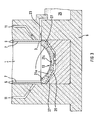
- a reactor pressure vessel (RPV) 1 in one Side view shown, which is in a reactor pit 3 is located.
- the reactor pit 3 is of a concrete foundation 5 formed. Between the RPV 1 and its outer casing insulation 7 is arranged.
- ventilation channels 11 may be provided for ventilation of the free spaces 9 .
- a chamber specifically an antechamber 13, arranged to collect meltdown from the RDB 1 serves in the event of a fault. It is followed by a channel 15, this on the input and output side with a bulkhead or Partition wall 17a, 17b is provided when the meltdown be destroyed and an outflow of the meltdown allow in the adjacent expansion chamber 19.
- the Bulkhead or partition 17a, 17b is also used as the exit plate designated.
- the RPV 1 If the RPV 1 is violated in the event of a malfunction, it can first Water leak out of it. This can be the case with a Main coolant line failure. It is undesirable that the water in the bottom of the reactor pit 3 accumulates, as the hot melt melt emerges A steam explosion can quickly develop from the RPV floor.
- the RPV 1 has an arrangement which has a filler 21 as an essential element for water displacement.
- the pre-chamber 13 and the channel 15 are filled with the filling body 21, which is composed of a plurality of partial filling bodies 21a to 21c.
- the filler 21 fills the cavities of the pre-chamber 13 in such a way that the largest possible fill factor is given. If possible, this should be over 80%, in particular 90 to 98%, especially approximately 90%.
- the amount of residual water remaining in the chamber should be well below 4m 3 , in particular 1m 3 , optimally 0.5m 3 . This prevents the sudden generation of a large amount of steam.
- the residual water can optionally be distributed over the narrow gaps between the partial packing elements 21a to 21c.
- An overflow 23 is arranged above the prechamber 13, through which the displaced water is directed into a reservoir 25 becomes. The water is therefore outside the endangered area. There is a flow and a slow evaporation prevented.
- the partial filling bodies 21a, 21c are of such a shape designed that they fill the antechamber 13 form-fitting. In the present example, this means that, for example up the dome-like shape of the bottom of the RDB 1 are adapted and down a crucible shape exhibit. In the area of the channel 15, the partial packing has 21b has a sheared rectangular shape.
- the partial packing is are modularly joined together so that a packing unit is formed.
- the partial packing 21a, 21b are dimensioned such that they are the channel 15 can be brought in or out. This also applies to the partial packing 21a, 21c, which are directly below the RPV 1 are arranged. This is particularly beneficial if retrospectively Maintenance work on RPV 1 should be carried out.
- the partial filling bodies 21a, 21b can thus be removed in a simple manner become. They preferably have a size that from Staff are easy to handle.
- the partial packing 21a, 21b, 21c means have, with which they are firmly connected can, e.g. B. a snap or plug connection.
- the partial packing can ensure problem-free installation 21a to 21c also with a numbering or a mechanical one Coding should be provided so that no errors Installation occurs.
- FIG 2 which shows a section along the line E-E, allows a plan view of the partial packing 21a and 21c.
- the Partial packing 21a are arranged in concentric rings and circular sector shaped.
- the central one Partial packing 21c is circular. It is also conceivable where appropriate, the partial packing in the form of a circular sector to train. It is essential for their dimensioning that retrofitted through duct 15 with installed RPV 1 can be introduced and removed and thanks to their modular structure Character form a homogeneous packing.
- the partial packing 21a to 21c In order to lose their filling function when meltdown occurs, the partial packing 21a to 21c must have a melting temperature have that above the temperature of the emerging Water and below which the meltdown lies.
- the Temperature can be about 100 to 350 ° C for the water and for the Meltdown should be above 2000 ° C.
- the melting temperature of the Packing body 21 must therefore be in the range between these temperatures lie.
- the partial filling bodies 21a to 21c are preferably hollow bodies educated. You can also use a Filler, in particular filled with a gas, so that there is a special advantageous effect when melting. This can be a cooling effect, for example.
- a suitable material for the partial packing 21a to 21c in particular metal or optionally also glass. These materials are easy to process and allow inexpensive Production.
- a metallic packing can, for example be welded.
- a glass packing can be used blow or press.
- a porous material in particular a foam or ceramic, burned or sintered material for the partial packing 21a to 21c use. This can be done very easily if necessary by cutting, observing the required Melting temperature is to be observed.
- a mineral Material e.g. Concrete is conceivable.
- the partial packing elements 21a, 21c which are located directly below the RPV calotte, one Achieve insulation effect, so that there is additional insulation - as usual - is not necessary.
- a multi-layer structure of the packing 21 is also possible, different qualities for the individual layers of partial packings can be used. 3 is an example of this in the area of reactor pit ventilation 26 shows an additional filler layer 27.
Landscapes
- Physics & Mathematics (AREA)
- Engineering & Computer Science (AREA)
- Plasma & Fusion (AREA)
- General Engineering & Computer Science (AREA)
- High Energy & Nuclear Physics (AREA)
- Structure Of Emergency Protection For Nuclear Reactors (AREA)
Description
- FIG 1
- einen Schnitt durch eine Reaktorgrube entlang der Linie A-A von FIG 2;
- FIG 2
- einen Schnitt durch die Reaktorgrube entlang der Linie E-E von FIG 1;
- FIG 3
- die Reaktorgrube in einem Schnitt entlang der Linie C-C von FIG 2.
Claims (14)
- Anordnung zur Wasserverdrängung in einer unterhalb eines Reaktordruckbehälters (1) liegenden Vorkammer (13) zum Auffangen von Kernschmelze, mit einem Füllkörper (21), der sich aus einer Vielzahl von Teilfüllkörpern (21a bis 21c) zusammensetzt, die bausteinartig aneinanderfügbar sind, wobei der Füllkörper (21) eine Schmelztemperatur oberhalb 100°C und unterhalb der Temperatur der Kernschmelze hat
dadurch gekennzeichnet,, daßdie Vorkammer (13) über einen Kanal (15) mit einer seitlichen Ausbreitungskammer (19) für die Kernschmelze verbunden ist,die Teilfüllkörper (21a bis 21c) derart dimensioniert sind, daß sie durch den Kanal (15) zur Vorkammer (13) ein- oder ausbringbar sind. - Anordnung nach Anspruch 1,
dadurch gekennzeichnet,
daß die Teilfüllkörper (21a bis 21c) durch einen Kanal (15) oder durch einen Tragschilddurchtritt zur Kammer (13) ein- oder ausbringbar sind. - Anordnung nach Anspruch 1 oder 2,
dadurch gekennzeichnet,
daß die Teilfüllkörper (21a, 21c)im Bereich des kalottenförmigen Bodens des Reaktordruckbehälters (1) kreissektor- oder kreisringsektorförmig ausgebildet sind. - Anordnung nach einem der Ansprüche 1 bis 3,
dadurch gekennzeichnet,
daß der Füllkörper (21) die Kammer (13) formschlüssig ausfüllt. - Anordnung nach einem der Ansprüche 1 bis 4,
dadurch gekennzeichnet,
daß der Füllkörper (21) einen Füllfaktor von mindestens 80 % in bezug auf die Kammergröße aufweist. - Anordnung nach Anspruch 5,
dadurch gekennzeichnet,
daß der Füllkörper (21) einen Füllfaktor von 90 % bis 98 % in bezug auf die Kammergröße aufweist. - Anordnung nach Anspruch 5 oder 6,
dadurch gekennzeichnet,
daß die in der Kammer (13) verbleibende Restwassermenge kleiner als 2 m3 ist. - Anordnung nach Anspruch 7,
dadurch gekennzeichnet,
daß die in der Kammer (13) verbleibende Restwassermenge kleiner als 1 m3 ist. - Anordnung nach einem der Ansprüche 1 bis 8,
dadurch gekennzeichnet,
daß die Teilfüllkörper (21a bis 21c) als Hohlkörper ausgebildet sind. - Anordnung nach Anspruch 9,
dadurch gekennzeichnet,
daß die Teilfüllkörper (21a bis 21c) aus Metall oder Glas gefertigt sind. - Anordnung nach Anspruch 9,
dadurch gekennzeichnet,
daß die Hohlkörper mit einem Füllstoff gefüllt sind. - Anordnung nach Anspruch 11,
dadurch gekennzeichnet,
daß die Hohlkörper mit Gas gefüllt sind. - Anordnung nach einem der Ansprüche 1 bis 8,
dadurch gekennzeichnet,
daß die Teilfüllkörper (21a bis 21c) aus einem porösen Material, einem Schaum, einem keramischen, gebrannten oder gesinterten Material oder einem betonartigen Material gefertigt sind. - Anordnung nach einem der Ansprüche 1 bis 13,
dadurch gekennzeichnet,
daß die Kammer (13) eine Ausbreitungskammer, Vorkammer (13) oder ein Kanal (15) für die Kernschmelze ist.
Applications Claiming Priority (2)
| Application Number | Priority Date | Filing Date | Title |
|---|---|---|---|
| DE19512286A DE19512286C1 (de) | 1995-04-05 | 1995-04-05 | Anordnung zur Wasserverdrängung |
| DE19512286 | 1995-04-05 |
Publications (2)
| Publication Number | Publication Date |
|---|---|
| EP0736877A1 EP0736877A1 (de) | 1996-10-09 |
| EP0736877B1 true EP0736877B1 (de) | 2000-05-31 |
Family
ID=7758555
Family Applications (1)
| Application Number | Title | Priority Date | Filing Date |
|---|---|---|---|
| EP96105110A Expired - Lifetime EP0736877B1 (de) | 1995-04-05 | 1996-03-29 | Kernschmelzeauffangvorrichtung mit Wasserverdrängunganordnung |
Country Status (2)
| Country | Link |
|---|---|
| EP (1) | EP0736877B1 (de) |
| DE (2) | DE19512286C1 (de) |
Families Citing this family (4)
| Publication number | Priority date | Publication date | Assignee | Title |
|---|---|---|---|---|
| JP2001503135A (ja) * | 1996-09-16 | 2001-03-06 | シーメンス アクチエンゲゼルシヤフト | 排水構造物 |
| JP4070178B2 (ja) | 1998-11-26 | 2008-04-02 | アレヴァ エンペー ゲゼルシャフト ミット ベシュレンクテル ハフツング | 溶融物の捕捉・冷却装置 |
| US6353651B1 (en) * | 1999-11-17 | 2002-03-05 | General Electric Company | Core catcher cooling by heat pipe |
| FR2837976B1 (fr) * | 2002-03-28 | 2004-11-12 | Commissariat Energie Atomique | Reacteur nucleaire comportant au niveau de ses structures des materiaux a changement de phase |
Family Cites Families (7)
| Publication number | Priority date | Publication date | Assignee | Title |
|---|---|---|---|---|
| US4036688A (en) * | 1975-04-09 | 1977-07-19 | The United States Of America As Represented By The United States Energy Research And Development Administration | Apparatus for controlling molten core debris |
| DE2653258C2 (de) * | 1976-11-24 | 1985-02-28 | Kernforschungszentrum Karlsruhe Gmbh, 7500 Karlsruhe | Verfahren zur Verringerung der Gefahren, die infolge eines Unfalles durch Niederschmelzen eines Kernreaktor-Kerns entstehen können, sowie eine Anordnung zur Durchführung des Verfahrens |
| DE2925680C2 (de) * | 1979-06-26 | 1981-08-27 | Hans Ulrich 7300 Esslingen Leiste | Auffangvorrichtung für schmelzende Brennelemente eines Atomreaktors |
| GB2236210B (en) * | 1989-08-30 | 1993-06-30 | Rolls Royce & Ass | Core catchers for nuclear reactors |
| DE4041295A1 (de) * | 1990-12-21 | 1992-07-02 | Siemens Ag | Kernreaktor-anlage, insbesondere fuer leichtwasserreaktoren, mit einer kernrueckhaltevorrichtung, verfahren zur notkuehlung bei einer solchen kernreaktor-anlage und verwendung turbulenzerzeugender deltafluegel |
| US5307390A (en) * | 1992-11-25 | 1994-04-26 | General Electric Company | Corium protection assembly |
| DE4319094A1 (de) * | 1993-06-08 | 1994-12-15 | Siemens Ag | Einrichtung und Verfahren zum Auffangen und Kühlen von Kernschmelze |
-
1995
- 1995-04-05 DE DE19512286A patent/DE19512286C1/de not_active Expired - Lifetime
-
1996
- 1996-03-29 EP EP96105110A patent/EP0736877B1/de not_active Expired - Lifetime
- 1996-03-29 DE DE59605336T patent/DE59605336D1/de not_active Expired - Fee Related
Also Published As
| Publication number | Publication date |
|---|---|
| DE19512286C1 (de) | 1996-10-17 |
| DE59605336D1 (de) | 2000-07-06 |
| EP0736877A1 (de) | 1996-10-09 |
Similar Documents
| Publication | Publication Date | Title |
|---|---|---|
| EP0563118B1 (de) | Kernrückhaltevorrichtung für kernreaktoranlage und notkühlung bei kernschmelze | |
| DE4032736C2 (de) | Kühleinrichtungen im Fundamentbereich eines Kernreaktors zur Kühlung einer Kernschmelze in einem hypothetischen Störfall | |
| DE4237245C2 (de) | Kernreaktor mit einer Einrichtung zur Bergung des Kerns nach dessen störfallbedingter Schmelzung | |
| EP0706707B1 (de) | Einrichtung zum auffangen und kühlen von kernschmelze | |
| EP0730776B1 (de) | Vorrichtung zum rückhalten einer kernschmelze innerhalb des ausbreitungsraums einer kernreaktoranlage | |
| DE68903787T2 (de) | Kernreaktor mit notkuehlwassereinspeiseeinrichtung. | |
| WO1994029876A1 (de) | Einrichtung und verfahren zum auffangen und kühlen von kernschmelze | |
| DE69304605T2 (de) | Auffangvorrichtung für geschmolzenes Kernreaktorspaltmaterial | |
| DE2430191C2 (de) | Wärmedämmende Abdeckung eines Verschlußdeckels eines Kernreaktorbehälters | |
| DE2643275C2 (de) | Seitenreflektor fuer hochtemperatur- kernreaktoren | |
| EP0819309B1 (de) | Einrichtung zum auffangen von kernschmelze aus einem reaktordruckbehälter | |
| WO1998012709A1 (de) | Anordnung zur wasserverdrängung | |
| DE19846057B4 (de) | Vorrichtung zum Kühlen und zum Schutz eines Reaktordruckbehälters bei Kernschmelzunfällen | |
| DE4339904A1 (de) | Vorrichtung zum Rückhalten einer heißen Schmelze, insbesondere einer Kernschmelze innerhalb der Ausbreitungskammer einer Kernreaktoranlage | |
| DE2138046C2 (de) | Druckbehälter | |
| DE2718493A1 (de) | Tragvorrichtung fuer den kern eines gasgekuehlten hochtemperaturreaktors grosser leistung | |
| DE19512286C1 (de) | Anordnung zur Wasserverdrängung | |
| DE2634356C3 (de) | Kerntechnische Anlage | |
| EP0702834B1 (de) | Einrichtung zum auffangen von kernschmelze aus einem reaktordruckbehälter | |
| DE3030510C2 (de) | ||
| DE3513019A1 (de) | Kernreaktor | |
| DE19653205C1 (de) | Auffangraum für eine Schmelze, insbesondere eine Kernschmelze einer Kernkraftanlage | |
| DE3927624A1 (de) | Waermedaemmsystem fuer flaechen, an denen ein heisser gasstrom entlanggefuehrt wird | |
| DE2506293C2 (de) | Hochtemperaturreaktor mit geschlossenem Gaskühlkreislauf | |
| WO1998025273A1 (de) | Behälter zur aufnahme und ausbreitung von kernschmelze sowie kernkraftanlage mit einem solchen behälter |
Legal Events
| Date | Code | Title | Description |
|---|---|---|---|
| PUAI | Public reference made under article 153(3) epc to a published international application that has entered the european phase |
Free format text: ORIGINAL CODE: 0009012 |
|
| AK | Designated contracting states |
Kind code of ref document: A1 Designated state(s): CH DE ES FR GB LI |
|
| 17P | Request for examination filed |
Effective date: 19970404 |
|
| 17Q | First examination report despatched |
Effective date: 19980324 |
|
| GRAG | Despatch of communication of intention to grant |
Free format text: ORIGINAL CODE: EPIDOS AGRA |
|
| GRAG | Despatch of communication of intention to grant |
Free format text: ORIGINAL CODE: EPIDOS AGRA |
|
| GRAG | Despatch of communication of intention to grant |
Free format text: ORIGINAL CODE: EPIDOS AGRA |
|
| GRAH | Despatch of communication of intention to grant a patent |
Free format text: ORIGINAL CODE: EPIDOS IGRA |
|
| GRAH | Despatch of communication of intention to grant a patent |
Free format text: ORIGINAL CODE: EPIDOS IGRA |
|
| GRAA | (expected) grant |
Free format text: ORIGINAL CODE: 0009210 |
|
| AK | Designated contracting states |
Kind code of ref document: B1 Designated state(s): CH DE ES FR GB LI |
|
| PG25 | Lapsed in a contracting state [announced via postgrant information from national office to epo] |
Ref country code: GB Free format text: LAPSE BECAUSE OF FAILURE TO SUBMIT A TRANSLATION OF THE DESCRIPTION OR TO PAY THE FEE WITHIN THE PRESCRIBED TIME-LIMIT Effective date: 20000531 Ref country code: ES Free format text: THE PATENT HAS BEEN ANNULLED BY A DECISION OF A NATIONAL AUTHORITY Effective date: 20000531 |
|
| REG | Reference to a national code |
Ref country code: CH Ref legal event code: EP |
|
| REF | Corresponds to: |
Ref document number: 59605336 Country of ref document: DE Date of ref document: 20000706 |
|
| ET | Fr: translation filed | ||
| GBV | Gb: ep patent (uk) treated as always having been void in accordance with gb section 77(7)/1977 [no translation filed] |
Effective date: 20000531 |
|
| PLBE | No opposition filed within time limit |
Free format text: ORIGINAL CODE: 0009261 |
|
| STAA | Information on the status of an ep patent application or granted ep patent |
Free format text: STATUS: NO OPPOSITION FILED WITHIN TIME LIMIT |
|
| PG25 | Lapsed in a contracting state [announced via postgrant information from national office to epo] |
Ref country code: LI Free format text: LAPSE BECAUSE OF NON-PAYMENT OF DUE FEES Effective date: 20010331 Ref country code: CH Free format text: LAPSE BECAUSE OF NON-PAYMENT OF DUE FEES Effective date: 20010331 |
|
| 26N | No opposition filed | ||
| REG | Reference to a national code |
Ref country code: CH Ref legal event code: PL |
|
| PGFP | Annual fee paid to national office [announced via postgrant information from national office to epo] |
Ref country code: FR Payment date: 20020318 Year of fee payment: 7 |
|
| PGFP | Annual fee paid to national office [announced via postgrant information from national office to epo] |
Ref country code: DE Payment date: 20020327 Year of fee payment: 7 |
|
| PG25 | Lapsed in a contracting state [announced via postgrant information from national office to epo] |
Ref country code: DE Free format text: LAPSE BECAUSE OF NON-PAYMENT OF DUE FEES Effective date: 20031001 |
|
| PG25 | Lapsed in a contracting state [announced via postgrant information from national office to epo] |
Ref country code: FR Free format text: LAPSE BECAUSE OF NON-PAYMENT OF DUE FEES Effective date: 20031127 |
|
| REG | Reference to a national code |
Ref country code: FR Ref legal event code: ST |