EP0736679B1 - Flexible tubular coupling member, for a motor-vehicle exhaust system - Google Patents
Flexible tubular coupling member, for a motor-vehicle exhaust system Download PDFInfo
- Publication number
- EP0736679B1 EP0736679B1 EP96830185A EP96830185A EP0736679B1 EP 0736679 B1 EP0736679 B1 EP 0736679B1 EP 96830185 A EP96830185 A EP 96830185A EP 96830185 A EP96830185 A EP 96830185A EP 0736679 B1 EP0736679 B1 EP 0736679B1
- Authority
- EP
- European Patent Office
- Prior art keywords
- bellow
- shaped element
- flexible tubular
- welded
- axis
- Prior art date
- Legal status (The legal status is an assumption and is not a legal conclusion. Google has not performed a legal analysis and makes no representation as to the accuracy of the status listed.)
- Expired - Lifetime
Links
Images


Classifications
-
- F—MECHANICAL ENGINEERING; LIGHTING; HEATING; WEAPONS; BLASTING
- F01—MACHINES OR ENGINES IN GENERAL; ENGINE PLANTS IN GENERAL; STEAM ENGINES
- F01N—GAS-FLOW SILENCERS OR EXHAUST APPARATUS FOR MACHINES OR ENGINES IN GENERAL; GAS-FLOW SILENCERS OR EXHAUST APPARATUS FOR INTERNAL-COMBUSTION ENGINES
- F01N13/00—Exhaust or silencing apparatus characterised by constructional features
- F01N13/18—Construction facilitating manufacture, assembly, or disassembly
- F01N13/1805—Fixing exhaust manifolds, exhaust pipes or pipe sections to each other, to engine or to vehicle body
- F01N13/1811—Fixing exhaust manifolds, exhaust pipes or pipe sections to each other, to engine or to vehicle body with means permitting relative movement, e.g. compensation of thermal expansion or vibration
- F01N13/1816—Fixing exhaust manifolds, exhaust pipes or pipe sections to each other, to engine or to vehicle body with means permitting relative movement, e.g. compensation of thermal expansion or vibration the pipe sections being joined together by flexible tubular elements only, e.g. using bellows or strip-wound pipes
-
- F—MECHANICAL ENGINEERING; LIGHTING; HEATING; WEAPONS; BLASTING
- F16—ENGINEERING ELEMENTS AND UNITS; GENERAL MEASURES FOR PRODUCING AND MAINTAINING EFFECTIVE FUNCTIONING OF MACHINES OR INSTALLATIONS; THERMAL INSULATION IN GENERAL
- F16L—PIPES; JOINTS OR FITTINGS FOR PIPES; SUPPORTS FOR PIPES, CABLES OR PROTECTIVE TUBING; MEANS FOR THERMAL INSULATION IN GENERAL
- F16L27/00—Adjustable joints; Joints allowing movement
- F16L27/10—Adjustable joints; Joints allowing movement comprising a flexible connection only
- F16L27/107—Adjustable joints; Joints allowing movement comprising a flexible connection only the ends of the pipe being interconnected by a flexible sleeve
- F16L27/11—Adjustable joints; Joints allowing movement comprising a flexible connection only the ends of the pipe being interconnected by a flexible sleeve the sleeve having the form of a bellows with multiple corrugations
- F16L27/111—Adjustable joints; Joints allowing movement comprising a flexible connection only the ends of the pipe being interconnected by a flexible sleeve the sleeve having the form of a bellows with multiple corrugations the bellows being reinforced
Definitions
- the present invention relates to the field of the flexible tubular coupling members for motor-vehicle exhaust systems, of the type comprising:
- a flexible tubular coupling member of this type for example, is disclosed in DE-A-35 06 626.
- Tubular members of the above indicated type have been used for example for coupling the outlet tube of the exhaust gas manifold of a motor-vehicle engine to the catalytic converter of the exhaust system.
- the bellow-shaped element achieves the object of reducing or nullifying the transmission of axial, bending and shear stresses due for example to the vibrations of the engine on its elastical supports with respect to the supporting structure of the motor-vehicle.
- said flexible coupling member must of course ensure a good sealing against the exhaust gases at high temperature (up to 1100° C).
- the present invention provides a flexible tubular coupling member of the type which has been indicated at the beginning, characterized in that said outer casing of metal braid has one end welded to the cooperating end of the bellow-shaped element and the opposite end terminating with a neck portion freely rotatably mounted around the cooperating end portion of the bellow-shaped element, and said bellow-shaped element has corrugations shaped and arranged in such a way as to be able to absorb at least partially relative torsional movements of the two tubes to be connected.
- said neck portion is welded to one end of the outer tubular casing of metal braid and is freely rotatably mounted on a bush welded to the respective end of the bellow-shaped element and having end edges bent outwardly to axially hold said neck portion.
- said flexible element has a corrugated wall with circumferential crests lying in inclined planes, (preferably at 45°) with respect to a plane orthogonal to the tube axis.
- said flexible element has a portion of the corrugated wall with longitudinal crests parallel to the tube axis and having a tapered or rectangular profile in a plane containing this axis.
- said flexible element has both said portions of the corrugated wall with longitudinal crests parallel to the tube axis, and a further portion of corrugated wall with circumferential crests lying in planes orthogonal to the tube axis.
- the shape and arrangement of the corrugations of the bellow-shaped element make the latter able to absorb at least partially or to nullify the transmission of torsional movements between the two connected tubes.
- Figure 1 shows a flexible tubular coupling member according to the prior art, used for example to connect the outlet tube of the exhaust manifold of an internal combustion engine to the catalytic converter of the exhaust system of the motor-vehicle.
- the flexible coupling member generally designated by reference numeral 1, comprises a bellow-shaped tubular element 2 having two end portions 3,4 and an intermediate bellow-shaped portion having a corrugated profile in a cross-sectional plane containing the axis 5 of the tubular member, with circumferential crests 6 lying in planes orthogonal to the axis 5.
- Reference numerals 7,8 respectively designate the ends of the two tubes to be connected, which are welded within the two end portions 3,4 of the bellow-shaped tubular element 2, which is a metal element.
- This element is surrounded by an outer casing of metal braid 9 which has its ends welded to the end portions 3,4 of the bellow-shaped element 2, by welded joints 10,11, which also provide for fixing of the two strengthening metal rings 12,13.
- Figures 2-4 relate to a first embodiment of the invention.
- the flexible tubular coupling member generally designated by reference numeral 14
- the flexible tubular coupling member also has a bellow-shaped metal tubular 15 having an intermediate bellow-shaped portion and two end portions 3,4 within which there are fixed the two tubes to be connected by welded joints 16,17.
- the bellow-shaped element has corrugations having circumferential crests lying in planes inclined at an angle A, preferably of 45°, with respect to axis 5 (or a plane orthogonal to this axis).
- an outer casing of metal braid 18 which has one end welded to the end portion 3 of the bellow-shaped element 15 and a tube 7 by means of said welded joint 16, whereas to the opposite end of this outer casing 18 there is welded a metal neck portion 19 (see also figure 3) which is freely rotatably mounted within a bush 20 which on its turn is welded to the end portion 4 of the bellow-shaped element 15 and the tube 8 by means of said welded joint 17.
- Bush 20 further has end edges bent radially outwardly to axially hold the neck portion 19.
- arrow G indicates the direction of the incoming exhaust gases.
- any torsional movement of the inlet tube 8 are not transmitted to the outer casing 18, since the tube 8 with the end portion 4 of the bellow-shaped element 15 and the bush 20 is free to rotate with respect to the neck portion 19 connected to the outer casing 18.
- the bellow-shaped element 15 is able to absorb partially or nullify the transmission of axial, bending, shear and also torsional movements.
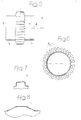
- Figures 5,6 relate to a second embodiment which is similar to that of figure 2 except for a different shape of the bellow-shaped element 15. Therefore, these figures show only this element, which in this case has cylindrical end portions 3,4 and an intermediate portion having a corrugated profile in a plane orthogonal to the axis 5 of the tube (see figure 6). In this case, therefore, the crests of the corrugations, designated by 6, are directed longitudinally, i.e. parallel to the axis 5. Furthermore, as clearly apparent from figure 5, the profile of each crest in a plane containing axis 5 (see figure 5) has a substantially tapered profile with sides which are more or less inclined (see the variant of figure 5 and figure 8) or a rectangular shape (figure 7).
- Figures 9,10 show a further variant in which the bellow-shaped element 15 has both a portion 15a identical to the central portion of the bellow-shaped element shown in figure 5,6, i.e. with crests 6 directed longitudinally and having a tapered or rectangular longitudinal profile, and a portion 15b of a conventional type, similar to that shown with reference to figure 1, with circumferential crests lying in planes orthogonal to axis 5.
- the portion 15b of the bellow-shaped element fulfils the task of absorbing the axial and bending movements, whereas portion 15a absorbs torsional movements.
Landscapes
- Engineering & Computer Science (AREA)
- General Engineering & Computer Science (AREA)
- Mechanical Engineering (AREA)
- Chemical & Material Sciences (AREA)
- Combustion & Propulsion (AREA)
- Exhaust Silencers (AREA)
- Joints Allowing Movement (AREA)
Applications Claiming Priority (2)
| Application Number | Priority Date | Filing Date | Title |
|---|---|---|---|
| IT95TO000264A IT1280844B1 (it) | 1995-04-06 | 1995-04-06 | "organo tubolare flessibile di collegamento, per impianti di scarico di autoveicoli" |
| ITTO950264 | 1995-04-06 |
Publications (2)
| Publication Number | Publication Date |
|---|---|
| EP0736679A1 EP0736679A1 (en) | 1996-10-09 |
| EP0736679B1 true EP0736679B1 (en) | 1997-10-15 |
Family
ID=11413468
Family Applications (1)
| Application Number | Title | Priority Date | Filing Date |
|---|---|---|---|
| EP96830185A Expired - Lifetime EP0736679B1 (en) | 1995-04-06 | 1996-04-02 | Flexible tubular coupling member, for a motor-vehicle exhaust system |
Country Status (4)
| Country | Link |
|---|---|
| EP (1) | EP0736679B1 (it) |
| DE (1) | DE69600074T2 (it) |
| ES (1) | ES2110860T3 (it) |
| IT (1) | IT1280844B1 (it) |
Families Citing this family (6)
| Publication number | Priority date | Publication date | Assignee | Title |
|---|---|---|---|---|
| DE19630222C1 (de) * | 1996-07-26 | 1998-02-19 | Daimler Benz Ag | Vorrichtung zum Abkoppeln von Torsionsschwingungen |
| DE19858634A1 (de) * | 1998-12-18 | 2000-06-21 | Volkswagen Ag | Flexschlauch |
| FI117109B (fi) * | 2003-12-15 | 2006-06-15 | Metso Automation Oy | Mittalaitteen tiiviste |
| ITTO20040371A1 (it) * | 2004-06-01 | 2004-09-01 | Flexider S R L | Giunto di disaccoppiamento per tubazioni di scarico di motori termici |
| DE202012011150U1 (de) * | 2012-11-21 | 2014-02-25 | Witzenmann Gmbh | Gestrickeanbindung für ein Entkoppelelement |
| DE102016103848B4 (de) | 2016-03-03 | 2025-06-18 | Witzenmann Gmbh | Flexibles Leitungsteil |
Family Cites Families (3)
| Publication number | Priority date | Publication date | Assignee | Title |
|---|---|---|---|---|
| US3019037A (en) * | 1959-05-21 | 1962-01-30 | Joseph M Caldwell | Universally flexible conduit joint |
| FR2324866A1 (fr) * | 1975-09-19 | 1977-04-15 | Tubest Sa | Raccord flexible pour systeme d'echappement de vehicules a moteur |
| JPS61107912U (it) * | 1984-12-19 | 1986-07-09 |
-
1995
- 1995-04-06 IT IT95TO000264A patent/IT1280844B1/it active IP Right Grant
-
1996
- 1996-04-02 EP EP96830185A patent/EP0736679B1/en not_active Expired - Lifetime
- 1996-04-02 ES ES96830185T patent/ES2110860T3/es not_active Expired - Lifetime
- 1996-04-02 DE DE69600074T patent/DE69600074T2/de not_active Expired - Fee Related
Also Published As
| Publication number | Publication date |
|---|---|
| ES2110860T3 (es) | 1998-02-16 |
| ITTO950264A0 (it) | 1995-04-06 |
| ITTO950264A1 (it) | 1996-10-06 |
| IT1280844B1 (it) | 1998-02-11 |
| DE69600074D1 (de) | 1997-11-20 |
| DE69600074T2 (de) | 1998-02-12 |
| EP0736679A1 (en) | 1996-10-09 |
Similar Documents
| Publication | Publication Date | Title |
|---|---|---|
| AU697712B2 (en) | Flexible coupler apparatus | |
| US5506376A (en) | Apparatus for absorbing vibrations in an exhaust system of a vehicle | |
| EP2307677B1 (en) | Sealed flexible coupling with torsion acceptance | |
| US6109661A (en) | Flexible coupler apparatus | |
| US5971439A (en) | Flexible coupler apparatus | |
| US5992896A (en) | Flexible coupler apparatus | |
| KR19980081299A (ko) | 배기매니폴드 부착장치 및 이의 제조방법 | |
| US6086110A (en) | Vibration decoupling connector for exhaust systems | |
| US6464257B1 (en) | Vibration decoupler apparatus | |
| US6554321B1 (en) | Decoupling sleeve for mounting in a motor vehicle exaust pipe | |
| EP0736679B1 (en) | Flexible tubular coupling member, for a motor-vehicle exhaust system | |
| US5882046A (en) | Dynamic stress controlling flexible hose section | |
| US5984372A (en) | Integrated flange-mesh ring assembly for decoupler apparatus | |
| US6047993A (en) | Arrangement for connection pipe pieces and method of making same | |
| US5542715A (en) | Metal expansion joint and vibration absorber apparatus for pipe systems | |
| US6669912B1 (en) | Flexible combined vibration decoupling exhaust connector and preliminary catalytic converter construction | |
| US20070132232A1 (en) | Decoupling element impervious to liquid fluids | |
| US5480194A (en) | Metal expansion joint vibration absorber apparatus for pipe systems | |
| US5956950A (en) | Arrangement for isolating torsional vibration | |
| GB2348935A (en) | Vehicle exhaust system with displaceable pipe portions | |
| GB2037922A (en) | Pipe Joint Structure | |
| GB1575892A (en) | Flexible pipe for exhaus gas pipes of internal combustion engines | |
| KR200183322Y1 (ko) | 자동차 배기관용 벨로우즈 | |
| JP3755212B2 (ja) | 自動車排気管用可撓性継手 | |
| WO2025193080A1 (en) | A multi-layer flexible coupling for exhaust system |
Legal Events
| Date | Code | Title | Description |
|---|---|---|---|
| PUAI | Public reference made under article 153(3) epc to a published international application that has entered the european phase |
Free format text: ORIGINAL CODE: 0009012 |
|
| AK | Designated contracting states |
Kind code of ref document: A1 Designated state(s): DE ES FR GB SE |
|
| 17P | Request for examination filed |
Effective date: 19970125 |
|
| GRAG | Despatch of communication of intention to grant |
Free format text: ORIGINAL CODE: EPIDOS AGRA |
|
| GRAH | Despatch of communication of intention to grant a patent |
Free format text: ORIGINAL CODE: EPIDOS IGRA |
|
| 17Q | First examination report despatched |
Effective date: 19970424 |
|
| GRAH | Despatch of communication of intention to grant a patent |
Free format text: ORIGINAL CODE: EPIDOS IGRA |
|
| GRAA | (expected) grant |
Free format text: ORIGINAL CODE: 0009210 |
|
| AK | Designated contracting states |
Kind code of ref document: B1 Designated state(s): DE ES FR GB SE |
|
| REF | Corresponds to: |
Ref document number: 69600074 Country of ref document: DE Date of ref document: 19971120 |
|
| ET | Fr: translation filed | ||
| REG | Reference to a national code |
Ref country code: ES Ref legal event code: FG2A Ref document number: 2110860 Country of ref document: ES Kind code of ref document: T3 |
|
| PLBE | No opposition filed within time limit |
Free format text: ORIGINAL CODE: 0009261 |
|
| STAA | Information on the status of an ep patent application or granted ep patent |
Free format text: STATUS: NO OPPOSITION FILED WITHIN TIME LIMIT |
|
| 26N | No opposition filed | ||
| REG | Reference to a national code |
Ref country code: GB Ref legal event code: IF02 |
|
| REG | Reference to a national code |
Ref country code: ES Ref legal event code: PC2A |
|
| REG | Reference to a national code |
Ref country code: GB Ref legal event code: 732E |
|
| REG | Reference to a national code |
Ref country code: FR Ref legal event code: TP |
|
| PGFP | Annual fee paid to national office [announced via postgrant information from national office to epo] |
Ref country code: FR Payment date: 20040301 Year of fee payment: 9 Ref country code: ES Payment date: 20040301 Year of fee payment: 9 |
|
| PGFP | Annual fee paid to national office [announced via postgrant information from national office to epo] |
Ref country code: SE Payment date: 20040316 Year of fee payment: 9 |
|
| PGFP | Annual fee paid to national office [announced via postgrant information from national office to epo] |
Ref country code: GB Payment date: 20040331 Year of fee payment: 9 |
|
| PGFP | Annual fee paid to national office [announced via postgrant information from national office to epo] |
Ref country code: DE Payment date: 20040621 Year of fee payment: 9 |
|
| PG25 | Lapsed in a contracting state [announced via postgrant information from national office to epo] |
Ref country code: GB Free format text: LAPSE BECAUSE OF NON-PAYMENT OF DUE FEES Effective date: 20050402 |
|
| PG25 | Lapsed in a contracting state [announced via postgrant information from national office to epo] |
Ref country code: SE Free format text: LAPSE BECAUSE OF NON-PAYMENT OF DUE FEES Effective date: 20050403 |
|
| PG25 | Lapsed in a contracting state [announced via postgrant information from national office to epo] |
Ref country code: ES Free format text: LAPSE BECAUSE OF NON-PAYMENT OF DUE FEES Effective date: 20050404 |
|
| PG25 | Lapsed in a contracting state [announced via postgrant information from national office to epo] |
Ref country code: DE Free format text: LAPSE BECAUSE OF NON-PAYMENT OF DUE FEES Effective date: 20051101 |
|
| EUG | Se: european patent has lapsed | ||
| GBPC | Gb: european patent ceased through non-payment of renewal fee |
Effective date: 20050402 |
|
| PG25 | Lapsed in a contracting state [announced via postgrant information from national office to epo] |
Ref country code: FR Free format text: LAPSE BECAUSE OF NON-PAYMENT OF DUE FEES Effective date: 20051230 |
|
| REG | Reference to a national code |
Ref country code: FR Ref legal event code: ST Effective date: 20051230 |
|
| REG | Reference to a national code |
Ref country code: ES Ref legal event code: FD2A Effective date: 20050404 |