EP0736627B1 - A resilient pad for a flat sheet ironing machine - Google Patents
A resilient pad for a flat sheet ironing machine Download PDFInfo
- Publication number
- EP0736627B1 EP0736627B1 EP96302331A EP96302331A EP0736627B1 EP 0736627 B1 EP0736627 B1 EP 0736627B1 EP 96302331 A EP96302331 A EP 96302331A EP 96302331 A EP96302331 A EP 96302331A EP 0736627 B1 EP0736627 B1 EP 0736627B1
- Authority
- EP
- European Patent Office
- Prior art keywords
- springs
- drum
- plate
- backing strip
- resilient pad
- Prior art date
- Legal status (The legal status is an assumption and is not a legal conclusion. Google has not performed a legal analysis and makes no representation as to the accuracy of the status listed.)
- Expired - Lifetime
Links
- 238000010409 ironing Methods 0.000 title claims description 17
- 210000000078 claw Anatomy 0.000 claims description 14
- XLYOFNOQVPJJNP-UHFFFAOYSA-N water Substances O XLYOFNOQVPJJNP-UHFFFAOYSA-N 0.000 description 5
- 238000003466 welding Methods 0.000 description 3
- ZAMOUSCENKQFHK-UHFFFAOYSA-N Chlorine atom Chemical compound [Cl] ZAMOUSCENKQFHK-UHFFFAOYSA-N 0.000 description 2
- 229910000831 Steel Inorganic materials 0.000 description 2
- 229910052801 chlorine Inorganic materials 0.000 description 2
- 239000000460 chlorine Substances 0.000 description 2
- 238000002788 crimping Methods 0.000 description 2
- 238000004519 manufacturing process Methods 0.000 description 2
- 239000010959 steel Substances 0.000 description 2
- 238000010276 construction Methods 0.000 description 1
- 238000005304 joining Methods 0.000 description 1
- 239000000463 material Substances 0.000 description 1
- 229910001220 stainless steel Inorganic materials 0.000 description 1
- 239000010935 stainless steel Substances 0.000 description 1
Images


Classifications
-
- D—TEXTILES; PAPER
- D06—TREATMENT OF TEXTILES OR THE LIKE; LAUNDERING; FLEXIBLE MATERIALS NOT OTHERWISE PROVIDED FOR
- D06F—LAUNDERING, DRYING, IRONING, PRESSING OR FOLDING TEXTILE ARTICLES
- D06F83/00—Coverings or pads for ironing or pressing members
Definitions
- This invention relates to a resilient pad for resiliently supporting a felt cover on a rotatable drum of a flat sheet ironing machine and to a flat sheet ironing machine equipped with such a pad.
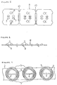
- FIG. 10 A conventional flat sheet ironing machine is shown in Figures 10 and 11.
- This ironing machine comprises a bed 21 which is provided with a heater (not shown) and a part cylindrical recess 21 a , and a cylindrical sheet roller 22 rotatably mounted in the recess 21 a .
- the roller 22 comprises a central drum 25 rotatable by a drive shaft 27 and a felt cover 23 resiliently supported on the drum 25 by a plurality of coil springs 24.
- the roller 22 is urged into contact with the bed 21 by pneumatically operated piston and cylinder units (not shown) at opposite ends of the drum.
- an item 28 to be ironed such as an item of bedding, e. g. a pillowcase or sheet, or an item of tableware, e.g. a napkin or tablecloth
- the item is heated by the heater provided in the bed 21 and the evaporated water content from the item passes through the felt cover 23 and enters the drum 25 through holes in the periphery thereof.
- the evaporated water content is then drawn from one end of the drum by suction.
- the coil springs 24 are integrally formed from a continuous length of wire and are supported at their inner ends by a backing strip 26 spirally wound about the periphery of the drum 25.
- Each spring 24 has two helically wound portions 24 a and 24 b joined together at the outer end of the spring by a transverse portion 24 c .
- the outer ends of the coil springs 24 are attached to the felt cover 23 by wire passed through the felt cover and beneath the backing strip or by T-pins pressed through the felt cover and obliquely into the coil springs 24.
- This is labour intensive and expensive. Also, there can be slippage between the felt cover and the coil springs. In addition, the area of contact between the springs and the felt cover is relatively small. Also, the pressure applied to the felt cover is unevenly distributed and this can result in poor finish quality of ironed items unless a thick felt cover is used. Thick covers add to the costs.
- the present invention seeks to provide a resilient pad which will resiliently support a felt cover on a rotatable drum of a flat sheet ironing machine and which will largely overcome the drawbacks of known springs.
- a resilient pad for resiliently supporting a felt cover on a rotatable drum of a flat sheet ironing machine, the resilient pad comprising a plurality of helically wound coil springs each having an inner end in use adjacent to the drum and an outer end in use adjacent to the felt cover, a backing strip windable about said drum, the inner end of each coil spring being supported by the backing strip with the coil springs spaced apart along the longitudinal extent of the backing strip, and a plurality of plate-like elements having inner and outer faces and being connected respectively to the outer ends of the coil springs, each plate-like element having one or more claws on its outer surface for making catching contact with the felt cover to ensure that, in use, the felt cover rotates with the drum, wherein each coil spring has two helically wound portions joined at the outer end of the spring by a transverse portion and wherein each plate-like element has two pairs of opposed lugs on its inner face, the lugs being crimped about the transverse portions of
- the transverse portions of the springs extend in a direction parallel to the longitudinal extent of the backing strip.
- the springs are integrally formed with one another from a continuous length of wire and portions of the wire between adjacent springs pass beneath the backing strip to anchor the inner ends of the springs to the backing strip.
- the claws are outwardly inclined.
- the lugs and the claws are pressed out of the plate-like elements.
- a flat sheet ironing machine comprising a bed having a part cylindrical recess and a roller mounted for rotation in the recess, the roller comprising a drum, a felt cover mounted on the drum and a resilient pad between the drum and the cover, the resilient pad comprising a plurality of helically wound coil springs each having an inner end adjacent to the drum and an outer end adjacent to the felt cover, a backing strip wound about the drum, the inner end of each coil spring being supported by the backing strip with the coils springs spaced apart along the longitudinal extent of the backing strip, and a plurality of plate-like elements having inner and outer faces and being connected respectively to the outer ends of the coil springs, each plate-like element having one or more claws on its outer surface in catching contact with the felt cover to ensure that, in use, the felt cover rotates with the drum, wherein each coil spring has two helically wound portions joined at the outer end of the spring by a transverse portion and wherein each plate-like element has two
- the flat sheet ironing machine further comprises means for urging the roller into contact with the bed.
- the resilient pad 1 shown therein is intended to replace the springs 24 of the conventional flat sheet ironing machine shown in, and described hereinbefore with reference to, Figures 10 and 11.
- the resilient pad 1 comprises a plurality of helically wound coil springs 3, each having an inner end adjacent to the drum of the ironing machine and an outer end adjacent to the felt cover 9, a backing strip 2 spirally wound about the drum and a plurality of plate-like elements 6 connected respectively to the outer ends of the coil springs 3.
- the springs 3 are supported in spaced apart relationship along the longitudinal extent of the backing strip 2.
- Each coil spring 3 is of bifilary construction having two oppositely wound helical portions joined at the outer end of the spring by a transverse portion 4.
- the springs 3 are integrally formed with one another from a continuous length of wire. Portions 5 of the wire between adjacent springs 3 pass beneath the backing strip 2 to anchor the inner ends of the springs 3 to the backing strip 2.
- the plate-like elements 6 are generally square when viewed in plan and have two spaced apart, outwardly inclined claws 8, which make catching contact with the felt cover 9 to drag the cover 9 round with the drum.
- the claws 8 are spaced apart perpendicularly of the longitudinal extent of backing strip 2 and are typically inclined at an angle of about 45° to the plane of the plate-like element 6, the free ends of the claws being at the leading edge when the drum is rotated.
- the plate-like elements 6 also have two spaced apart positioning means 7 for positioning the plate-like element 6 relative to the spring 3.
- Each positioning means 7 comprises two inwardly extending lugs 7 a for locating the transverse portion 4 of the spring 3 therebetween.
- the two positioning means 7 are located at opposite ends of the transverse portion 4 which is arranged to extend in a direction parallel to the longitudinal extent of the backing strip 2 and perpendicularly to a line joining the two claws 8. To this end, the outermost end of each helically wound portion of each spring, is bent by more than 90° with respect to the transverse portion 4.
- Each plate-like element 6 is secured to the transverse portion 4 of a respective spring 3 by welding the lugs 7 a (and/or the part of the plate-like element intermediate the two pairs of lugs) to the transverse portion 4 or, as shown in Figures 8 and 9, by crimping the lugs 7 a about the transverse portion 4.
- the lugs 7 a may be of greater length than they need be when welding the plate-like element 6 to the spring 3.
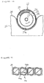
- the plate-like elements 6 are made from an elongate strip R.
- the strip R is stamped to leave adjacent plate-like elements 6 connected to one another by frangible sections 10. Holes 8 a are punched out so that the claws 8 can be pressed from the strip R without damaging the punch and die.
- the lugs 7 a are also pressed from the strip R. The plate-like elements 6 are then separated from one another.
- the plate-like elements 6 are then placed on the springs 3, such as by using robots, and connected to the springs 3 by welding or crimping as aforesaid.
- the springs 3, backing strip 2 and plate-like elements 6 are all typically formed from stainless steel especially when the water contains large quantities of chlorine, although in some countries, where water quality is high and the water contains low quantities of chlorine, the use of low cost galvanised steel wire for the springs and galvanised steel for the plate-like elements and the backing strip can reduce production costs.
- a resilient pad as hereinbefore described has a much greater contact area with the felt than the coil springs used hitherto.
- the spring pressure is therefore much more evenly distributed on the felt resulting in greater torque and less risk of marking items to be ironed.
- the provision of the claws provides a simple and inexpensive means of ensuring that the felt is dragged round by the drum and prevents slippage between the felt cover and the resilient pad. It also makes it simpler to replace the felt cover. Indeed, when using a resilient pad as herein described, the felt cover can be replaced by the owner or operator of the flat sheet ironing machine without the need to call out a skilled technician. This avoids any unnecessary down time which could be disastrous to the owner's business and it also saves significant costs. Also, the resilient pad as hereinbefore described is much cheaper to produce than previously used laminated or plate springs and will not be permanently deformed by lumps in items to be ironed.
Landscapes
- Engineering & Computer Science (AREA)
- Textile Engineering (AREA)
- Irons (AREA)
Applications Claiming Priority (3)
| Application Number | Priority Date | Filing Date | Title |
|---|---|---|---|
| JP7099441A JP2729770B2 (ja) | 1995-04-03 | 1995-04-03 | シーツロール機用ばね |
| JP99441/95 | 1995-04-03 | ||
| JP9944195 | 1995-04-03 |
Publications (2)
| Publication Number | Publication Date |
|---|---|
| EP0736627A1 EP0736627A1 (en) | 1996-10-09 |
| EP0736627B1 true EP0736627B1 (en) | 2000-05-24 |
Family
ID=14247495
Family Applications (1)
| Application Number | Title | Priority Date | Filing Date |
|---|---|---|---|
| EP96302331A Expired - Lifetime EP0736627B1 (en) | 1995-04-03 | 1996-04-02 | A resilient pad for a flat sheet ironing machine |
Country Status (5)
| Country | Link |
|---|---|
| US (1) | US5653049A (da) |
| EP (1) | EP0736627B1 (da) |
| JP (1) | JP2729770B2 (da) |
| DE (1) | DE69608492T2 (da) |
| DK (1) | DK0736627T3 (da) |
Families Citing this family (5)
| Publication number | Priority date | Publication date | Assignee | Title |
|---|---|---|---|---|
| US6043376A (en) * | 1998-08-06 | 2000-03-28 | Boehringer Ingelheim Pharmaceuticals, Inc. | Synthesis of alpha-methyl, alpha-substituted amino acids |
| US6341767B1 (en) * | 1999-06-29 | 2002-01-29 | Joseph B. Seale | Spring for valve control in engines |
| JP2007082790A (ja) | 2005-09-22 | 2007-04-05 | San-Ai Industries Inc | シーツロール機用スプリングパッド |
| DE102010022182A1 (de) * | 2010-05-21 | 2011-11-24 | Herbert Kannegiesser Gmbh | Verfahren zur Herstellung einer Feder für eine Unterbewicklung einer Mangelwalze, eine Unterbewicklung und eine Feder |
| DE102019135083A1 (de) * | 2019-12-19 | 2021-06-24 | Danfoss A/S | Hydraulische Axialkolbenmaschine |
Family Cites Families (7)
| Publication number | Priority date | Publication date | Assignee | Title |
|---|---|---|---|---|
| US1592564A (en) * | 1926-05-14 | 1926-07-13 | Hamilton Charles Edwin | Ironing pad |
| US1924973A (en) * | 1932-08-10 | 1933-08-29 | Robert J Beede | Spring cushion |
| US2190146A (en) * | 1939-05-03 | 1940-02-13 | George W Bristol | Flexible pressing machine pad |
| GB650212A (en) * | 1948-12-15 | 1951-02-14 | D & J Tullis Ltd | Improvements relating to resilient padding for laundry machinery |
| US2708322A (en) * | 1952-10-01 | 1955-05-17 | Zeidler Mfg Company Inc | Spring pad structures |
| DE2625201C3 (de) * | 1976-06-04 | 1979-11-08 | Karl Erk Inh. W. Pratzer, 4710 Luedinghausen | Elastisch nachgiebige Zwischenlage für Heißmangelwalzen |
| JP3174385B2 (ja) * | 1992-04-01 | 2001-06-11 | 三愛工業株式会社 | シーツロール機に用いるスプリングパッド |
-
1995
- 1995-04-03 JP JP7099441A patent/JP2729770B2/ja not_active Expired - Lifetime
-
1996
- 1996-04-02 EP EP96302331A patent/EP0736627B1/en not_active Expired - Lifetime
- 1996-04-02 DK DK96302331T patent/DK0736627T3/da active
- 1996-04-02 DE DE69608492T patent/DE69608492T2/de not_active Expired - Lifetime
- 1996-04-03 US US08/627,109 patent/US5653049A/en not_active Expired - Lifetime
Also Published As
| Publication number | Publication date |
|---|---|
| JP2729770B2 (ja) | 1998-03-18 |
| DE69608492D1 (de) | 2000-06-29 |
| EP0736627A1 (en) | 1996-10-09 |
| JPH08276099A (ja) | 1996-10-22 |
| US5653049A (en) | 1997-08-05 |
| DK0736627T3 (da) | 2000-08-14 |
| DE69608492T2 (de) | 2001-02-01 |
Similar Documents
| Publication | Publication Date | Title |
|---|---|---|
| EP0736627B1 (en) | A resilient pad for a flat sheet ironing machine | |
| AU2003232915B2 (en) | Woven fabric belt device | |
| CA2206087A1 (en) | Seam for paper machine clothing | |
| US5011060A (en) | Roll for spreading and guiding a fabric web | |
| EP0970805B1 (en) | Unit for joining paper sheets together in corrugated board manufacturing equipment | |
| US4584747A (en) | Ironing/mangle roller | |
| CN1884647B (zh) | 一种用在梳理机中的装置 | |
| US4844422A (en) | Barbed tape barrier | |
| US1973044A (en) | Ironer roll pad unit | |
| JP2002039243A (ja) | ウエーブコイルばね | |
| US4606792A (en) | Endless sieve band or composite band for paper machines | |
| US5012545A (en) | Rotary cleaning and polishing pad | |
| US2172767A (en) | Method of making press pads | |
| EP1767688B1 (en) | Spring pad for an ironing machine | |
| US5860200A (en) | Mattress cover securement apparatus | |
| US2122165A (en) | Resilient ironing surface | |
| JPH02117537A (ja) | カード類搬送部のピンチローラ機構 | |
| JP3174385B2 (ja) | シーツロール機に用いるスプリングパッド | |
| JPS6012547Y2 (ja) | 平物仕上機におけるロ−ルカバ−の固定具 | |
| US3045323A (en) | Combination roll and attaching device for ironer rolls | |
| JP2009506231A (ja) | 向上した柔軟性の螺旋リンク布 | |
| JPH0256972B2 (da) | ||
| DE2625201C3 (de) | Elastisch nachgiebige Zwischenlage für Heißmangelwalzen | |
| JPS5940958Y2 (ja) | 平物仕上機のロ−ルカバ−の固定具 | |
| KR200319653Y1 (ko) | 내열 부직포 롤의 제조장치 및 제조 방법 |
Legal Events
| Date | Code | Title | Description |
|---|---|---|---|
| PUAI | Public reference made under article 153(3) epc to a published international application that has entered the european phase |
Free format text: ORIGINAL CODE: 0009012 |
|
| AK | Designated contracting states |
Kind code of ref document: A1 Designated state(s): BE CH DE DK ES FR GB IT LI NL SE |
|
| 17P | Request for examination filed |
Effective date: 19970325 |
|
| 17Q | First examination report despatched |
Effective date: 19981202 |
|
| GRAG | Despatch of communication of intention to grant |
Free format text: ORIGINAL CODE: EPIDOS AGRA |
|
| GRAG | Despatch of communication of intention to grant |
Free format text: ORIGINAL CODE: EPIDOS AGRA |
|
| GRAG | Despatch of communication of intention to grant |
Free format text: ORIGINAL CODE: EPIDOS AGRA |
|
| GRAH | Despatch of communication of intention to grant a patent |
Free format text: ORIGINAL CODE: EPIDOS IGRA |
|
| GRAH | Despatch of communication of intention to grant a patent |
Free format text: ORIGINAL CODE: EPIDOS IGRA |
|
| ITF | It: translation for a ep patent filed | ||
| GRAA | (expected) grant |
Free format text: ORIGINAL CODE: 0009210 |
|
| AK | Designated contracting states |
Kind code of ref document: B1 Designated state(s): BE CH DE DK ES FR GB IT LI NL SE |
|
| PG25 | Lapsed in a contracting state [announced via postgrant information from national office to epo] |
Ref country code: NL Free format text: LAPSE BECAUSE OF FAILURE TO SUBMIT A TRANSLATION OF THE DESCRIPTION OR TO PAY THE FEE WITHIN THE PRESCRIBED TIME-LIMIT Effective date: 20000524 Ref country code: LI Free format text: LAPSE BECAUSE OF FAILURE TO SUBMIT A TRANSLATION OF THE DESCRIPTION OR TO PAY THE FEE WITHIN THE PRESCRIBED TIME-LIMIT Effective date: 20000524 Ref country code: ES Free format text: THE PATENT HAS BEEN ANNULLED BY A DECISION OF A NATIONAL AUTHORITY Effective date: 20000524 Ref country code: CH Free format text: LAPSE BECAUSE OF FAILURE TO SUBMIT A TRANSLATION OF THE DESCRIPTION OR TO PAY THE FEE WITHIN THE PRESCRIBED TIME-LIMIT Effective date: 20000524 |
|
| REG | Reference to a national code |
Ref country code: CH Ref legal event code: EP |
|
| REF | Corresponds to: |
Ref document number: 69608492 Country of ref document: DE Date of ref document: 20000629 |
|
| ET | Fr: translation filed | ||
| REG | Reference to a national code |
Ref country code: DK Ref legal event code: T3 |
|
| PG25 | Lapsed in a contracting state [announced via postgrant information from national office to epo] |
Ref country code: SE Free format text: LAPSE BECAUSE OF FAILURE TO SUBMIT A TRANSLATION OF THE DESCRIPTION OR TO PAY THE FEE WITHIN THE PRESCRIBED TIME-LIMIT Effective date: 20000824 |
|
| NLV1 | Nl: lapsed or annulled due to failure to fulfill the requirements of art. 29p and 29m of the patents act | ||
| REG | Reference to a national code |
Ref country code: CH Ref legal event code: PL |
|
| PLBE | No opposition filed within time limit |
Free format text: ORIGINAL CODE: 0009261 |
|
| STAA | Information on the status of an ep patent application or granted ep patent |
Free format text: STATUS: NO OPPOSITION FILED WITHIN TIME LIMIT |
|
| 26N | No opposition filed | ||
| REG | Reference to a national code |
Ref country code: GB Ref legal event code: IF02 |
|
| PGFP | Annual fee paid to national office [announced via postgrant information from national office to epo] |
Ref country code: GB Payment date: 20050330 Year of fee payment: 10 |
|
| PGFP | Annual fee paid to national office [announced via postgrant information from national office to epo] |
Ref country code: DK Payment date: 20050415 Year of fee payment: 10 |
|
| PG25 | Lapsed in a contracting state [announced via postgrant information from national office to epo] |
Ref country code: GB Free format text: LAPSE BECAUSE OF NON-PAYMENT OF DUE FEES Effective date: 20060402 |
|
| PG25 | Lapsed in a contracting state [announced via postgrant information from national office to epo] |
Ref country code: DK Free format text: LAPSE BECAUSE OF NON-PAYMENT OF DUE FEES Effective date: 20060501 |
|
| REG | Reference to a national code |
Ref country code: DK Ref legal event code: EBP |
|
| GBPC | Gb: european patent ceased through non-payment of renewal fee |
Effective date: 20060402 |
|
| REG | Reference to a national code |
Ref country code: FR Ref legal event code: PLFP Year of fee payment: 20 |
|
| PGFP | Annual fee paid to national office [announced via postgrant information from national office to epo] |
Ref country code: DE Payment date: 20150421 Year of fee payment: 20 |
|
| PGFP | Annual fee paid to national office [announced via postgrant information from national office to epo] |
Ref country code: BE Payment date: 20150420 Year of fee payment: 20 Ref country code: FR Payment date: 20150421 Year of fee payment: 20 Ref country code: IT Payment date: 20150428 Year of fee payment: 20 |
|
| REG | Reference to a national code |
Ref country code: DE Ref legal event code: R071 Ref document number: 69608492 Country of ref document: DE |