EP0736624B1 - Triaxial weaving machine - Google Patents
Triaxial weaving machine Download PDFInfo
- Publication number
- EP0736624B1 EP0736624B1 EP96104813A EP96104813A EP0736624B1 EP 0736624 B1 EP0736624 B1 EP 0736624B1 EP 96104813 A EP96104813 A EP 96104813A EP 96104813 A EP96104813 A EP 96104813A EP 0736624 B1 EP0736624 B1 EP 0736624B1
- Authority
- EP
- European Patent Office
- Prior art keywords
- warp
- yarn
- weft
- discs
- weaving machine
- Prior art date
- Legal status (The legal status is an assumption and is not a legal conclusion. Google has not performed a legal analysis and makes no representation as to the accuracy of the status listed.)
- Expired - Lifetime
Links
Images


Classifications
-
- D—TEXTILES; PAPER
- D03—WEAVING
- D03D—WOVEN FABRICS; METHODS OF WEAVING; LOOMS
- D03D41/00—Looms not otherwise provided for, e.g. for weaving chenille yarn; Details peculiar to these looms
- D03D41/004—Looms for three-dimensional fabrics
-
- D—TEXTILES; PAPER
- D03—WEAVING
- D03D—WOVEN FABRICS; METHODS OF WEAVING; LOOMS
- D03D41/00—Looms not otherwise provided for, e.g. for weaving chenille yarn; Details peculiar to these looms
Definitions
- This invention relates to triaxial weaving machines comprising an upright framing which at the top supports a rotary cage for applying warp spools and driving them to unroll their yarns and for compensating the length differences between the lengths of warp yarns delivered and the ones entrained, a stationary device positioned underneath for rearranging the warp yarns from a preceding circular distribution to a subsequent planar two-plane distribution thereof, an assembly positioned underneath for creating a warp-yarn Z -system and a warp-yarn S -system, respectively, a shed-forming and weft laying-in attachment positioned underneath, and, finally, a section of the machine accommodating the triaxially woven fabric.
- a "Triaxial Weaving" prospectus (particularly relevant): Prospectus No. F-16645; TW 2000 Triaxial Weaving Machine produced by Barber-Colman Company , Textile Machinery Division (Address: 1300 Rock Street, Rockford, Illinois, U.S.A., 61101).
- US-A-4 105 052 discloses a triaxial weaving machine according to the preamble of claim 1, respectively claim 10.
- warp yarns are conducted through and shifted to and fro, respectively (creating a Z -system and an S -system of the warp, respectively), according to a program by heddles, i.e. elements similar to platines. It is an enormous work to thread the heddles when creating a warp, and it is hardly possible to detect the respective heddle which got unthreaded in the course of weaving because the heddles move and therefore continuously change their position.
- a mechanism for spontaneous compensating the length differences of the warp yarns is arranged in the middle of a warp-spool collar. It is extremely inconvenient to draw in the yarns (from the outer side of the warp-spool collar to the inside thereof and downwards) when preparing a warp, and it is especially complicated to draw in a broken yarn.
- the weaving preparations for a triaxial weaving machine essentially differ from those for biaxial ones.
- a triaxial weaving machine is introduced into a weaving room furnished for manufacturing biaxial woven fabrics, it occupies quite an amount of additional space and staff has to be additionally trained.
- all main elements of the proposed machine without exception are rotational, which fact by itself results in a possible increase of the manufacturing capacity of the machine.
- the warp spools being arranged in two levels it is possible, in comparison to the prior art, to increase the extent of the warp spools and the total mass of the warp.
- a pair of trusses traversing the respective two warp spools and supporting guiding bars, suitably three per spool, and short-circuit (disconnection) bars, two per spool, with the warp yarns being led from each warp spool at the inner side of the machine upwards around the inner guiding bar belonging to the respective three-bar group, then reoriented to the outer side of the machine and led over the said two disconnecting bars and the middle bar of the said guiding-bar group and, finally, around the outer guiding bar of the three-bar group downwards by the outer side of the respective spool.
- warp yarns are led near the outer border of the machine, which makes them easily surveyable and accessible.
- the said cage of the machine provides ribbed arcuate rods, suitably four 90-grade rods, one per each spool, with two opposing rods of the said four rods positioned in an appropriate horizontal plane and the other two opposing rods positioned in another horizontal plane (mounting reasons), with the warp yarns being led from above downwards by the outer mantle surface of the said arcuate rods.
- the spirally wound shaft according to the invention for shifting the warp yarns of the warp-yarn Z -system and the warp-yarn S -system, respectively, along the path of the weft suitably comprises four ridges with each of them terminating, at the end where a warp yarn leaves the warp-yarn Z/S -system and enters the warp-yarn S/Z -system, by a pusher for assisting the transfer of the yarns from one warp-yarn system to the other one.
- the invention foresees two embodiments of spirally wound shafts, one of them providing zigzag-shaped ridges and the other one providing smooth (continuous) ridges.
- the cam spindle of the invention consists of a plurality of radially emphasized annular discs and a plurality of radially emphasized annular cam-shaped spacers, the discs and the spacers being arranged alternatingly, with the thickness of the discs being negligibly small and the peripheral contour of the discs being square with rounded corners, the discs being incorporated to form an assembly so that they are uniformly oriented with their rounded corners residing in flush with the generatrices of the spindle, whereas the spacers are basically circular elements, whose outer diameter equals the sides of the square of the discs, and one, two, or three cams being formed integrally with them, the cam(s) each being oriented to the respective corner(s) of the square of the discs.
- the weft shaft of the invention consists of a plurality of radially emphasized annular discs and a plurality of annular spacers, the discs and the spacers being arranged alternatingly, with the thickness of the discs being negligibly small and the discs each being basically an annular element, whose outer diameter equals that of the spacers, and comprising prongs which each consists of three sections, namely a radial section connected to the basic ring of the disc, a tangential section connected, by one of its ends, to the said radial section, and a further radial section formed integrally with another end of the said tangential section and oriented to the axis of the disc, so that the three said sections of the prong create a cavity, whose bottom resides in the plane of the weft shaft, which includes the axis of the weft shaft.
- the outer edge of the tangential section of the prong is formed smoothly arcuately, which makes it possible to beat up the weft lying underneath to the woven fabric.
- the weft shaft of the invention consists of a plurality of radially emphasized annular discs and a plurality of cam spacers, the discs and the spacers being arranged alternatingly, with the thickness of the discs being negligibly small and the discs each being basically an annular element, whose outer diameter equals that of an annular base of the cam spacers, and comprising prongs which each consists of three sections, namely a radial section connected to the basic ring of the disc, a tangential section connected, by one of its ends, to the said radial section, and a further radial section formed integrally with another end of the said tangential section and oriented to the axis of the disc, so that the three said sections of the prong create a cavity, whose bottom resides in the plane of the weft shaft, which includes the axis of the weft shaft.
- the cam of the cam spacer is positioned so that its radial edge being rear edge with respect to the rotation flushes with the bottom of the said cavity, and the outer edge of the tangential section of the prong is formed smoothly arcuately, which makes it possible to beat up the weft lying underneath to the woven fabric.
- the proposed machine is designed by starting from a stationary framework 100. It consists of four uprights 1 positioned on corners of a square field and interconnected at the top by a top cross 102 composed of interconnecting legs 2 residing over the diagonals of the said square field. Onto the legs 2 a flange collar 3 of a housing of a deep-groove-type radial ball bearing 5 or the like is fastened by screws 4 from above in the middle of their junction.
- Each upright 1 provides an inwardly projected cantilever beam 11 (see Fig. 5) superposed by a respective leg 2 and spaced from the latter.
- An annular rail 10 is placed on the free ends of the cantilever beams 11 and appropriately fixed.
- One of four sides of the base of the framework of the machine is chosen to be the front side (the weaver's working place), the opposite side is thus the rear side of the machine (a cloth beam resides there) and the two remaining sides are lateral sides.
- an upper traverse 19 and a lower traverse 32 are fixed on the pertaining two uprights 1 of each lateral side.
- a vertical bearing plate 33 for supporting a weaving assembly of the machine is fastened on each pair of the traverses 19 and 32 on their outer side, suitably in the middle between the uprights 1.
- a respective mechanical outfit such as bearings 31 of the cloth beam, a support 37 for an electromotor 20 for propelling the weaving assembly, a support 38 for an electromotor 12 for rotating the rotary cage provided with warp spools etc.
- a scaffold 34 which surrounds it and is provided with a respective guardrail and appropriate access steps 35.
- a rotary cage 104 for receiving the warp spools is incorporated into the framework 100 of the machine by means of the adjustably incorporated top bearing 5, whereby the cage 104 is essentially retained in the radial direction, and by means of the annular rail 10, whereby the cage 104 is supported in vertical direction.
- the cage 104 consists of four vertical legs 14 forming edges of a square-base parallelepiped, which suitably corresponds to one half of the base square area of the framework 100.
- the legs 14 occupy practically the entire vertical clearance between the top legs 2 above and the upper traverses 19 below.
- At their lower end the legs 14 are interconnected on their outer side by means of bars 18, and at their upper end they are interconnected by a top cross 104' (Fig. 4) fastened on top surfaces of the legs 14.
- the top cross 104' interconnects, similarly to the top cross 102, the legs 14 in diagonal directions of the respective square base.
- a hollow flanged shaft 9 (Fig. 8) is inserted from below in the middle of the top cross 104' and fastened thereto by means of a further set of screws 4, the shaft 9 protruding up through the cross 104' and being held in the top bearing 5.
- Free ends of arms 39 of the top cross 104' radially project beyond the annular rail 10 and to their front surfaces a ring gear 6 is fastened.
- the outer diameter of the ring gear 6 suitably corresponds to the horizontal clearance between the bearing plates 33.
- a rolling assembly 107 resting on the rail 10 is attached from below to each arm of the top cross 104'.
- the cage 104 together with all pertaining parts and the warp spools is, as an autonomous assembly, suspended from above on the rail 10.
- the support 38 for an electromotor is fastened to a respective cantilever beam 11 and holds the electromotor 12, whose axis provides a pinion mating the ring gear 6.
- a horizontal truss 13 is fastened at the outer side of the legs, with two trusses 13 which reside at two opposite sides of the cage being arranged at a specific level and the other two trusses 13 which reside at the other two opposite sides of the cage being arranged at the other level.
- each pair of trusses 13 there belong two pairs of bearings 15 (one pair on each side of the cage) for suspending the shafts of the warp spools, the bearings 15 being fastened to the legs 14 in the planes which cross the trusses 13 belonging to the latter and spaced down from them.
- bearings 15 there are foreseen eight bearings for suspending four warp spools (one warp spool per cageside), with two opposite warp spools being positioned in one level and the remaining two warp spools being positioned in the other level.
- each leg 14 of the cage provides a respective electromotor (not shown), whose arrangement and configuration depend on the design of warp drums (of prior art) for warp spools.
- the electromotors are energized by means of a rotary sliding contact (known per se ) over cables introduced from outside through the hollow shaft 9.
- ribbed arcuate 90-grade circular-section rods 17 are fastened to the legs 14 by means of radial web girders 16 (Fig. 6), the rods 17 constituting a full ring with two opposite rods 17 positioned in a specific level and the remaining two opposite rods positioned in another level (similarly to the arrangement of the warp spools).
- a layout of rods makes it possible to obtain a spacing between a last yarn of a spool 43 and a first yarn of a neighbouring spool 43, which is equal to a common spacing between two neighbouring yarns of a respective spool.
- the rods 17 are designed to have disc-type annular ribs 59, which are suitably mutually equidistant.
- the bearing plates 33 support a weaving assembly 108 incorporated there by quick assembling and disassembling, preferably requiring two steps - insertion and turning, and turning and removal, respectively.
- the following functions are realized in the weaving assembly 108:
- the weaving assembly 108 comprises, at the top, two mutually parallel, smooth, spaced intake rollers 21, which create a gap port (see also Figs. 9 to 11 and 21 to 23, respectively).
- two horizontally shaped lateral-shutter masks 22 are arranged, which are intended to define the weaving width, i.e. the position of the respective border yarns of the warp.
- a pair of mutually parallel spirally wound shafts 23 is positioned, which nearly touch each other and serve for shifting the warp yarns along the weft.
- a cam spindle 24 i.e.
- a spindle for forming/closing the shed is arranged, which is superposed with respect to a weft shaft 25, i.e. a shaft for laying in and beating up a weft yarn.
- a weft shaft 25' i.e. a spindle for forming/closing the shed, for laying in and beating up a weft yarn is arranged below one of the said shafts.
- the weft shaft 25, the cam spindle 24 and the spirally wound shafts 23 are provided with toothed pulleys (Fig. 3), with a toothed belt 28 (alternatively a chain) being placed enveloping them as well as a toothed pulley 27 of the already mentioned electromotor 20.
- tension pulleys 29 are arranged at its back side.
- weft shaft 25' and the spirally wound shafts 23 are provided with toothed pulleys (Fig. 19), with a toothed belt 28 (alternatively a chain) being placed enveloping them as well as a toothed pulley 27 of the already mentioned electromotor 20.
- a first guiding roll 26 for woven fabric and parallelly to it, below the bearings 31 of the cloth beam 44, a further guiding roll 26 for the woven fabric are incorporated.
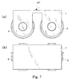
- the rolling assembly 107 (Fig. 7) consists of a holder 7 and of two flanged rollers 8 positioned in running direction one after another, whose axes are suitably oriented to the middle of the machine.
- the flanges of the rollers 8 reside at the inner side of the rail 10.
- Each horizontal truss 13 is designed to have three pairs of bearings 36 for supporting journal pins of guiding bars 60, i.e. suitably a pair at each end and a pair in the middle of the truss 13. Between the pair (each of two pairs) of bearings 36 arranged at the end of the truss and the one arranged in the middle thereof, each truss 13 is designed to have two bearings 61 for supporting two short-circuit (disconnecting) bars 40.
- appropriate control riders one per warp yarn
- the disconnecting bars 40 are positioned over the disconnecting bars 40, the riders being supported by the yarns at a distance from the bars 40. If a yarn gets broken, the force to retain the rider at a distance over the bar 40 disappears; the rider drops onto the bar 40, it establishes a short circuit and hence an impulse to stop the machine.
- the lateral shutter mask 22 is designed to have an arcuate recess 62 (Fig. 13) so that the intake rollers 21 and the lateral shutter masks 22 create, in plan, an essentially oblong hole to rearrange the distribution of warp yarns 46, which are slowly rotatably shifted (in the direction of arrow A in Fig. 13) together with the cage 104 from the preceding circular funnel-kind layout over the rollers 21 to a subsequent planar two-plane distribution thereof in the weaving assembly 108.
- the recess 62 is positioned nonconcentrically in the mask 22, which in turn is actually positioned concentrically in the machine, with the axis of symmetry of the recess 62 residing in the given case, in plan, in flush with a mantle generatrix of the roller 21, namely the one which receives the respective yarn.
- the spirally wound shaft 23 of Figs. 14 and 15 is constructed similarly to a four-thread screw, whose threads as such are essentially zigzag-shaped.
- the said threads are constructed in the form of four lamellar ridges 63 (of negligible thickness) wound spirally along a cylindrical surface, the ridges being mutually parallel and creating uniform spiral grooves 57.
- each ridge 63 is composed of regularly gauged length sections, which in this case are circumferential sections 48 and spiral (inclined) sections 56, respectively, which in assembled state form a zigzag-shaped spiral.
- All the circumferential sections 48 are equal to each other and positioned by their ends to reside in flush with a generatrix of the mantle of the cylinder, and all the inclined sections 56 are mutually equal and positioned by their ends to reside in flush with the (same) generatrix of the mantle of the cylinder.
- the ridges 63 of a respective shaft 23 are left-handed and the ones of the other shaft 23 right-handed.
- each ridge 63 terminates in a pusher 49 (for controlled shifting of a yarn being a last yarn 46 at a respective moment, from one shaft 23 to another one, the respective yarn representing there a new starting yarn), which is suitably designed to freely enter the working area of the neighbouring shaft 23 when rotating.
- the mantle configuration of the shaft 23 of Figs. 14 and 15 is practically composed of ridges 63 as separate components and of spacers arranged therebetween, the said components and spacers being positionally correctly fixed on the body of the shaft 23.
- Figs. 16 and 17 show a modified embodiment of the shaft 23, whose ridges 58 are smooth (continuous) spirals.
- the cam spindle 24 provides a mantle configuration composed of a plurality of radially emphasized annular discs 50 (of a negligible thickness) and a plurality of radially emphasized annular cam-shaped spacers 51, the discs and the spacers being arranged alternatingly, with the density of the discs and spacers corresponding to two spacers 51 per spiral groove 57 of the shaft 23.
- the peripheral contour of the discs 50 is square with rounded corners (Figs. 9 to 11), the discs being incorporated to form an assembly so that their rounded corners reside in flush with the generatrices of the spindle.
- the spacers 51 in turn are basically circular elements, whose outer diameter equals the sides of the square of the discs 50, and have one or more cams 52 being formed integrally with them, whose outer contour prevailingly corresponds to that of the discs 50; merely at the tip of the cam, the latter is shortened to an extent required to guide a yarn between the discs 50.
- the number of the cams 52 at individual spacers 51 as well as the circumferential position (orientation) thereof in an assembled spindle 24 depend on the intended kind of the triaxial woven fabric. In the weaving assembly 108, the cam spindle 24 is arranged so that when the shed is closed (Fig. 9), the discs 50 butt against the warp, with the side of the disc 50 being parallel to the warp.
- the proposed cam spindle 24 makes it possible to create weaves providing four wefts in its repeat of pattern, i.e. it can create sixteen different weaves.
- a cam spindle can also be foreseen for e.g. six wefts, which results in sixty-four different weaves so that, as to the weaves, all customers' demands can be met.
- the weft shaft 25, too, provides a mantle configuration composed of a plurality of radially emphasized annular discs 64 (of a negligible thickness) and a plurality of annular spacers 53, the discs and the spacers being arranged alternatingly.
- the graduation of the configuration corresponds to that of the spirally wound shaft 23. All discs 64, on the one hand, and all spacers 53, on the other hand, are equal to each other.
- the disc 64 consists of a ring (no reference numeral) which, observed in axial direction, registers with the spacer 53, and of formed prongs 54 - four in the given embodiment.
- the prong 54 comprises three main sections (no separate reference numerals): a radial section connected to the basic ring of the disc, a tangential section connected, by one of its ends, to the said radial section, and a further radial section formed integrally with the other end of the said tangential section and oriented to the axis of the disc.
- the three said sections of the prong 54 arranged in the above-mentioned manner create a cavity 65.
- the bottom of one respective cavity 65 and the bottom of an opposite cavity 65 reside in the same plane, which is the diametral plane of the weft shaft.
- the tangential section of the prong 54 is oriented contrary to the rotation of the weft shaft 25.
- the spacers 53 are simple rings.
- the weft shaft 25' provides a mantle configuration composed of a plurality of radially emphasized annular discs 64 (of a negligible thickness) and a plurality of cam spacers 53', the discs and the spacers being arranged alternatingly.
- the graduation of the configuration corresponds to that of the spirally wound shaft 23.
- All discs 64, on the one hand, and all spacers 53', on the other hand, are equal to each other.
- the disc 64 consists of a basic ring (no reference numeral) which, observed in radial direction, registers with the basic ring of the spacer 53', and of formed prongs 54 - four in the given embodiment.
- the prong 54 comprises three main sections (no separate reference numerals): a radial section connected to the basic ring of the disc, a tangential section connected, by one of its ends, to the said radial section, and a further radial section formed integrally with the other end of the said tangential section and oriented to the axis of the disc.
- the three said sections of the prong 54 arranged in the above-mentioned manner create a cavity 65.
- the bottom of one respective cavity 65 and the bottom of an opposite cavity 65 reside in the same plane, which is the diametral plane of the weft shaft.
- the tangential section of the prong 54 is oriented contrary to the rotation of the weft shaft 25'.
- the cam spacer 53' each consists of a basic ring (no reference numeral) and a radial cam 66.
- the said cam is designed to provide a straight rear edge flushing with the bottom of the cavity 65.
- the invention makes it possible to lay in wefts irrespective of whether the machine operates continuously or discontinuously. If the machine works continuously, the weft is laid in by air/water jet techniques or by projectile-type devices, if discontinuously, then other techniques can be applied as well.
- the travelling of a weft carrier is synchronized with the rotation of the cam spindle 24 and the weft shaft 25, i.e.
- the cams 52 are arranged forming a spiral along the cam spindle 24 and a channel (for the travelling of the weft carrier) formed by the cavities 65 is coiled forming an analogous helix; at the other approach the cams 52 reside in flush with a generatrix of the cam spindle 24 and the said channel of the weft shaft 25 is straight and in flush with the mantle generatrix of the weft shaft 25.
- the travelling of a weft carrier is synchronized with the rotation of the weft shaft 25', i.e.
- the cams 66 are arranged forming a spiral along the weft shaft 25' and a channel (for the travelling of the weft carrier) formed by the cavities 65 is coiled forming an analogous helix; at the other approach the cams 66 reside in flush with a generatrix of the weft shaft 25'.
- the said channel of the weft shaft 25' is then straight and in flush with the mantle generatrix of the weft shaft 25'.
- each bearing plate 33 a recess 30 (Fig. 3) is provided, which corresponds to the cavity 65 and is located in registry with cavities 65 of a respective longitudinal series of prongs 54 when the bottom of cavities 65 lies in a horizontal plane.
- a device (not shown) known per se for placing a weft carrier 55 (Fig. 10) is arranged at this position.
- rollers (rider weights) 45 (Fig. 12) belong, which as such are loose parts that can be lost.
- the roller 45 provides two intermediate circumferential ribs (partitions) in addition to the end ribs so that the working length of the roller is divided into three sections.
- the ends of the roller 45 are spherical. The rollers 45 thus touch each other substantially spotwise without interfering with each other when tilting, rising and lowering individually in the course of the operation of the machine.
- the machine is designed to apply four warp spools 43 (Fig. 8).
- the yarns of each warp spool 43 are wound onto a warp shaft 41, which in turn is inserted in respective bearings 15 and connected torque-transferringly with an unwinding motor (not shown).
- Reels 42 carrying the warp spools 43 are placed so that, initially, free ends of yarns are suspended at the radially outer side thereof.
- the yarns 46 of a respective spool 43 are arranged to run at the radially inner side of the spool upwards to the nearest central guiding bar 60 placed on trusses 13, whereupon they are deflected to run horizontally over the short-circuit (disconnecting) bars 40 up the end pair of guiding bars 60.
- warp yarns run radially outwards up the outer border of the machine (a similarity to the machines for manufacturing biaxial woven fabrics).
- the yarns 46 are stretched by placing the burdening rollers 45 in the space between the outer guiding bars 60.
- Each burdening roller 45 is foreseen to stretch a plurality of yarns.
- the yarns 46 so stretched are disposed equidistantly on the ribbed arcuate rods 17, then controlled by the spiral grooves 57 of the shafts 23 and laid between the discs 50 of the cam spindle 24 and the discs 64 of the weft shaft 25.
- the final step of laying the warp is to put the control riders onto the yarns over the short-circuit (disconnecting) bars 40.
- the unwinding propelling of spools 43, the rotation of the respective parts of the weaving assembly 108 and of the cloth beam 44 mutually correspond to each other.
- the unwinding electromotor of a respective warp spool switches on when the tension of the warp exceeds a predetermined value.
- the advance at unwinding the warp is constant and each weft is followed by a warp unwinding step.
- the spirally wound shafts 23 hold the tense warp yarns in their spiral grooves 57.
- the warp yarns 46 move transversely along them, with the yarns belonging to one of them moving in one direction ( Z warp) and those belonging to the other one moving in another direction ( S warp).
- the respective pusher 49 departs and pushes it to the port of a just released groove of the neighbouring shaft 23.
- each yarn when reaching the end of the shaft one yarn at one end of each shaft per 90° of the rotation of shafts 23 changes the system of yarns (from Z to S and from S to Z , respectively).
- the mantle configuration of the cam spindle 24 is assembled for forming a shed according to a predetermined weave pattern.
- the warp yarns are shifted to either direction along the weft so that a respective yarn of the S/Z system in each subsequent step of forming the sheds resides at a location which is progressed for one pitch along the shaft 24 in comparison with its previous location.
- the weft shaft 25 (alternatively: the weft shaft 25') of the invention also serves as a loom batten, here a rotational one.
- the warp yarns are shifted to either direction along the weft after the weft was laid in and the shed was closed (Fig. 9).
- the prongs 54 beat up (by their back edges) the weft just laid in to a woven fabric 47.
- the machine provides no oscillating parts, so that the working capacity of the machine of the invention can be significantly increased in comparison with that of known machines. Since the forming of the warp proceeds from inside outwards, which is similar to techniques with machines for manufacturing biaxial woven fabrics, and since the weaving preparation as such is essentially equal to that for biaxial woven fabrics, the incorporation of machines for manufacturing triaxial woven fabrics in a weaving room for manufacturing biaxial woven fabrics does not require any extra training of the workers nor any additional investments in the weaving preparation.
- the warp yarns are easily accessible on a prevailing length thereof; if a yarn breaks, it can be simply and quickly incorporated into the woven fabric by means of an auxiliary thread. The aim of the invention has thus been achieved.
Description
- This invention relates to triaxial weaving machines comprising an upright framing which at the top supports a rotary cage for applying warp spools and driving them to unroll their yarns and for compensating the length differences between the lengths of warp yarns delivered and the ones entrained, a stationary device positioned underneath for rearranging the warp yarns from a preceding circular distribution to a subsequent planar two-plane distribution thereof, an assembly positioned underneath for creating a warp-yarn Z-system and a warp-yarn S-system, respectively, a shed-forming and weft laying-in attachment positioned underneath, and, finally, a section of the machine accommodating the triaxially woven fabric.
- Such machines or their components and assemblies are classified in the International Patent Classification to:
- D 03
-
C 13/00; - D 03
-
D 13/00, 41/00, 47/18, 47/20, 49/02, 49/12, 49/14, 49/16, 49/68, 51/18, 51/20, 51/28. - The following prior art references have been considered when creating the captioned invention. References in bold type have been considered particularly relevant if taken alone.
- US 3,998,250 Townsend, 4,006,759 Darsie, 4,022,250 Trost, 4,022253 Trost, 4,031,922 Trost, 4,040,451 Trost et al., 4,105,052 Trost et al., and 4,512,373 Trost;
- CH 612,223 (≡ DE 2,634,966) Kulczycki, and 617,232 (≡ GB 1,532,426) Halton et al.;
- DE 2,645,369 Townsend;
- GB 1,570,456 Kulczycki, and 2,115,021 (shed-forming apparatus).
-
- A "Triaxial Weaving" prospectus (particularly relevant): Prospectus No. F-16645; TW 2000 Triaxial Weaving Machine produced by Barber-Colman Company, Textile Machinery Division (Address: 1300 Rock Street, Rockford, Illinois, U.S.A., 61101).
- US-A-4 105 052 discloses a triaxial weaving machine according to the preamble of
claim 1, respectively claim 10. - The known machines are packed with oscillating elements. This fact per se represents a serious manufacturing limitation of the machine. For laying in a weft, rapier-type attachments are used which in this special field are known to be the slowest devices.
- In the shed forming area warp yarns are conducted through and shifted to and fro, respectively (creating a Z-system and an S-system of the warp, respectively), according to a program by heddles, i.e. elements similar to platines. It is an enormous work to thread the heddles when creating a warp, and it is hardly possible to detect the respective heddle which got unthreaded in the course of weaving because the heddles move and therefore continuously change their position.
- A mechanism for spontaneous compensating the length differences of the warp yarns is arranged in the middle of a warp-spool collar. It is extremely inconvenient to draw in the yarns (from the outer side of the warp-spool collar to the inside thereof and downwards) when preparing a warp, and it is especially complicated to draw in a broken yarn.
- Owing to the division of the quantity of warp yarns in the weaving preparation to quite a great number of warp spools (eight in the prior art), the weaving preparations for a triaxial weaving machine essentially differ from those for biaxial ones. When a triaxial weaving machine is introduced into a weaving room furnished for manufacturing biaxial woven fabrics, it occupies quite an amount of additional space and staff has to be additionally trained.
- It is a basic object of the present invention to increase the manufacturing capacity of a triaxial weaving machine to a level that could make use of modern high-capacity weft laying-in attachments avoiding any big differences between operating a triaxial weaving machine and a biaxial one.
- The object of the invention is achieved by the triaxial weaving machines of
claim 1, respectively claim 10. Advantageous embodiments of the invention are subject of claims 2-9 and 11-18. - According to the invention, all main elements of the proposed machine without exception are rotational, which fact by itself results in a possible increase of the manufacturing capacity of the machine. By the warp spools being arranged in two levels it is possible, in comparison to the prior art, to increase the extent of the warp spools and the total mass of the warp.
- Besides, according to the invention, in either level of warp spools in the rotary cage, there is foreseen a pair of trusses traversing the respective two warp spools and supporting guiding bars, suitably three per spool, and short-circuit (disconnection) bars, two per spool, with the warp yarns being led from each warp spool at the inner side of the machine upwards around the inner guiding bar belonging to the respective three-bar group, then reoriented to the outer side of the machine and led over the said two disconnecting bars and the middle bar of the said guiding-bar group and, finally, around the outer guiding bar of the three-bar group downwards by the outer side of the respective spool.
- Thus the warp yarns are led near the outer border of the machine, which makes them easily surveyable and accessible.
- Below the lower warp-spool level the said cage of the machine provides ribbed arcuate rods, suitably four 90-grade rods, one per each spool, with two opposing rods of the said four rods positioned in an appropriate horizontal plane and the other two opposing rods positioned in another horizontal plane (mounting reasons), with the warp yarns being led from above downwards by the outer mantle surface of the said arcuate rods.
- The spirally wound shaft according to the invention for shifting the warp yarns of the warp-yarn Z-system and the warp-yarn S-system, respectively, along the path of the weft suitably comprises four ridges with each of them terminating, at the end where a warp yarn leaves the warp-yarn Z/S-system and enters the warp-yarn S/Z-system, by a pusher for assisting the transfer of the yarns from one warp-yarn system to the other one.
- The invention foresees two embodiments of spirally wound shafts, one of them providing zigzag-shaped ridges and the other one providing smooth (continuous) ridges.
- The cam spindle of the invention consists of a plurality of radially emphasized annular discs and a plurality of radially emphasized annular cam-shaped spacers, the discs and the spacers being arranged alternatingly, with the thickness of the discs being negligibly small and the peripheral contour of the discs being square with rounded corners, the discs being incorporated to form an assembly so that they are uniformly oriented with their rounded corners residing in flush with the generatrices of the spindle, whereas the spacers are basically circular elements, whose outer diameter equals the sides of the square of the discs, and one, two, or three cams being formed integrally with them, the cam(s) each being oriented to the respective corner(s) of the square of the discs.
- The weft shaft of the invention consists of a plurality of radially emphasized annular discs and a plurality of annular spacers, the discs and the spacers being arranged alternatingly, with the thickness of the discs being negligibly small and the discs each being basically an annular element, whose outer diameter equals that of the spacers, and comprising prongs which each consists of three sections, namely a radial section connected to the basic ring of the disc, a tangential section connected, by one of its ends, to the said radial section, and a further radial section formed integrally with another end of the said tangential section and oriented to the axis of the disc, so that the three said sections of the prong create a cavity, whose bottom resides in the plane of the weft shaft, which includes the axis of the weft shaft.
- It is a further feature of the said prong that the outer edge of the tangential section of the prong is formed smoothly arcuately, which makes it possible to beat up the weft lying underneath to the woven fabric.
- Alternatively, the weft shaft of the invention consists of a plurality of radially emphasized annular discs and a plurality of cam spacers, the discs and the spacers being arranged alternatingly, with the thickness of the discs being negligibly small and the discs each being basically an annular element, whose outer diameter equals that of an annular base of the cam spacers, and comprising prongs which each consists of three sections, namely a radial section connected to the basic ring of the disc, a tangential section connected, by one of its ends, to the said radial section, and a further radial section formed integrally with another end of the said tangential section and oriented to the axis of the disc, so that the three said sections of the prong create a cavity, whose bottom resides in the plane of the weft shaft, which includes the axis of the weft shaft.
- The cam of the cam spacer is positioned so that its radial edge being rear edge with respect to the rotation flushes with the bottom of the said cavity, and the outer edge of the tangential section of the prong is formed smoothly arcuately, which makes it possible to beat up the weft lying underneath to the woven fabric.
- Hereinafter, the invention is disclosed in detail on the basis of an embodiment of a triaxial weaving machine shown in the drawing attached.
- In the drawing:
- Fig. 1
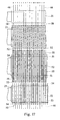
- is an elevational view of the front side of a machine prepared to apply warp spools and to arrange the warp, with the actually existing weft laying-in attachments being omitted from the drawing,
- Fig. 2
- is a plan view to Fig. 1 with scaffolding and access stairs omitted from the drawing,
- Fig. 3
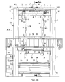
- is a side view of the machine as seen in the direction III in Fig. 1,
- Fig. 4
- is a sectional view taken according to the section line IV-IV in Fig. 1,
- Fig. 5
- is a sectional view taken according to the section line V-V in Fig. 1,
- Fig. 6
- is a sectional view taken according to the section line VI-VI in Fig. 1,
- Fig. 7
- shows a detail of the machine, namely a rolling assembly represented in an elevational view (a) and in plan view (b), respectively,
- Fig. 8
- is a side view of the machine according to Fig. 3 in operation, the upper and the lower central parts of the machine being shown as a sectional elevation,
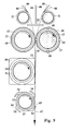
- Fig. 9
- shows a large-scale weaving end of the machine of Fig. 8, wherefrom there can be seen a weft laying-in and weft beating-up attachment, a superposed shed-forming assembly (the shed is closed), a superposed assembly for creating a warp-yarn Z-system and a warp-yarn S-system, respectively, and a superposed device for rearranging warp yarns from a preceding circular distribution to a subsequent planar two-plane distribution thereof,
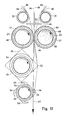
- Fig. 10
- is the weaving end of Fig. 9 in an open-shed state (with a weft being laid in),
- Fig. 11
- is the weaving end of Figs. 9 and 10 in a state prior to closing the shed (with a weft yarn being beaten up to the woven fabric),
- Fig. 12
- is an elevational view (a) and a side view (b) of a burdening roller (rider weight) for automatic compensation of the length of warp yarns,
- Fig. 13
- is a sectional view of the machine taken along the line XIII-XIII in Fig. 1, showing a large-scale detail of the machine when operating,
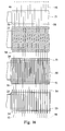
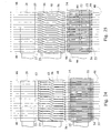
- Fig. 14
- is an elevational view of a part (an end part) of the weaving end of the machine of Figs. 9 to 11 in the state of the shed being closed,
- Fig. 15
- is similar to Fig. 14 with an open shed,
- Fig. 16
- > is similar to Fig. 14, with respective spirally wound shafts being modified,
- Fig. 17
- is similar to Fig. 15, with the spirally wound shafts of Fig. 16 being used;
- Fig. 18
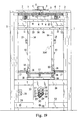
- is, similarly to Fig. 1, an elevational view of the front side of an alternative machine prepared to apply warp spools and to arrange the warp, with the actually existing weft laying-in attachments being omitted from the drawing,
- Fig. 19
- is a side view of the machine as seen in the direction XIX in Fig. 18,
- Fig. 20
- is, similarly to Fig. 8, a side view of the machine according to Fig. 19 in operation, the upper and the lower central parts of the machine being shown as a sectional elevation,
- Fig. 21
- shows, similarly to Fig. 9, a large-scale weaving end of the machine of Fig. 20, wherefrom there can be seen a shed-forming weft-laying-in and weft-beating-up assembly (the shed is closed), a superposed assembly for creating a warp-yarn Z-system and a warp-yarn S-system, respectively, and a superposed device for rearranging warp yarns from a preceding circular distribution to a subsequent planar two-plane distribution thereof,
- Fig. 22
- is, similarly to Fig. 10, the weaving end of Fig. 21 in an open-shed state (with a weft being laid in),
- Fig. 23
- is, similarly to Fig. 11, the weaving end of Figs. 21 and 22 in a state prior to closing the shed (with a weft yarn being beaten up to the woven fabric),
- Fig. 24
- is, similarly to Fig. 14, an elevational view of a part (an end part) of the weaving end of the machine of Figs. 21 to 23 in the state of the shed being closed,
- Fig. 25
- is similar to Fig. 24 with an open shed,
- Fig. 26
- is similar to Fig. 24, with respective spirally wound shafts being modified, and
- Fig. 27
- is similar to Fig. 25, with the spirally wound shafts of Fig. 26 being used.
- The proposed machine is designed by starting from a
stationary framework 100. It consists of fouruprights 1 positioned on corners of a square field and interconnected at the top by atop cross 102 composed of interconnectinglegs 2 residing over the diagonals of the said square field. Onto the legs 2 aflange collar 3 of a housing of a deep-groove-typeradial ball bearing 5 or the like is fastened byscrews 4 from above in the middle of their junction. - Each
upright 1 provides an inwardly projected cantilever beam 11 (see Fig. 5) superposed by arespective leg 2 and spaced from the latter. Anannular rail 10 is placed on the free ends of the cantilever beams 11 and appropriately fixed. One of four sides of the base of the framework of the machine is chosen to be the front side (the weaver's working place), the opposite side is thus the rear side of the machine (a cloth beam resides there) and the two remaining sides are lateral sides. - On the lateral sides of the framework of the machine, an
upper traverse 19 and alower traverse 32 are fixed on the pertaining twouprights 1 of each lateral side. Avertical bearing plate 33 for supporting a weaving assembly of the machine is fastened on each pair of thetraverses uprights 1. - To the stationary part of the machine there also belongs a respective mechanical outfit such as
bearings 31 of the cloth beam, asupport 37 for anelectromotor 20 for propelling the weaving assembly, asupport 38 for anelectromotor 12 for rotating the rotary cage provided with warp spools etc. - Finally, to the framework of the machine there also belongs a
scaffold 34 which surrounds it and is provided with a respective guardrail and appropriate access steps 35. - A
rotary cage 104 for receiving the warp spools is incorporated into theframework 100 of the machine by means of the adjustably incorporatedtop bearing 5, whereby thecage 104 is essentially retained in the radial direction, and by means of theannular rail 10, whereby thecage 104 is supported in vertical direction. - The
cage 104 consists of fourvertical legs 14 forming edges of a square-base parallelepiped, which suitably corresponds to one half of the base square area of theframework 100. Thelegs 14 occupy practically the entire vertical clearance between thetop legs 2 above and theupper traverses 19 below. At their lower end thelegs 14 are interconnected on their outer side by means ofbars 18, and at their upper end they are interconnected by a top cross 104' (Fig. 4) fastened on top surfaces of thelegs 14. The top cross 104' interconnects, similarly to thetop cross 102, thelegs 14 in diagonal directions of the respective square base. A hollow flanged shaft 9 (Fig. 8) is inserted from below in the middle of the top cross 104' and fastened thereto by means of a further set ofscrews 4, theshaft 9 protruding up through the cross 104' and being held in thetop bearing 5. - Free ends of
arms 39 of the top cross 104' radially project beyond theannular rail 10 and to their front surfaces aring gear 6 is fastened. The outer diameter of thering gear 6 suitably corresponds to the horizontal clearance between the bearingplates 33. - A rolling assembly 107 (Fig. 7) resting on the
rail 10 is attached from below to each arm of the top cross 104'. Thecage 104 together with all pertaining parts and the warp spools is, as an autonomous assembly, suspended from above on therail 10. - The
support 38 for an electromotor is fastened to arespective cantilever beam 11 and holds theelectromotor 12, whose axis provides a pinion mating thering gear 6. - In the cage region vertically between the
ring gear 6 above and the interconnecting bars 18 below, to each pair of legs 14 (four legs create four pairs thereof) ahorizontal truss 13 is fastened at the outer side of the legs, with twotrusses 13 which reside at two opposite sides of the cage being arranged at a specific level and the other twotrusses 13 which reside at the other two opposite sides of the cage being arranged at the other level. - To each pair of
trusses 13, there belong two pairs of bearings 15 (one pair on each side of the cage) for suspending the shafts of the warp spools, thebearings 15 being fastened to thelegs 14 in the planes which cross thetrusses 13 belonging to the latter and spaced down from them. Totally, there are foreseen eight bearings for suspending four warp spools (one warp spool per cageside), with two opposite warp spools being positioned in one level and the remaining two warp spools being positioned in the other level. - According to the invention an individual drive for unrolling the warp spools is provided, which is similar to the prior art. To this end, each
leg 14 of the cage provides a respective electromotor (not shown), whose arrangement and configuration depend on the design of warp drums (of prior art) for warp spools. The electromotors are energized by means of a rotary sliding contact (known per se) over cables introduced from outside through thehollow shaft 9. - In a vertical clearance between the lower pair of
bearings 15 and the interconnecting bars 18 of the cage, four ribbed arcuate 90-grade circular-section rods 17 (see also Fig. 13) are fastened to thelegs 14 by means of radial web girders 16 (Fig. 6), therods 17 constituting a full ring with twoopposite rods 17 positioned in a specific level and the remaining two opposite rods positioned in another level (similarly to the arrangement of the warp spools). Such a layout of rods makes it possible to obtain a spacing between a last yarn of aspool 43 and a first yarn of a neighbouringspool 43, which is equal to a common spacing between two neighbouring yarns of a respective spool. Therods 17 are designed to have disc-typeannular ribs 59, which are suitably mutually equidistant. - The bearing
plates 33 support a weavingassembly 108 incorporated there by quick assembling and disassembling, preferably requiring two steps - insertion and turning, and turning and removal, respectively. The following functions are realized in the weaving assembly 108: - the warp yarns previously arranged in the form of a circular funnel are rearranged to two vertical planar arrangements, the said two arrangements residing closely to each other and comprising equal numbers of yarns;
- two extreme positions of residing the border warp yarns are defined;
- the yarns of a planar layout are reoriented to form a warp yarn Z-system and the yarns of another planar layout reoriented to form a warp yarn S-system;
- a safe transfer of each border yarn from the warp yarn S/Z-system to the warp yarn Z/S-system is guaranteed;
- sheds are formed and closed, respectively, and the warp is freely shifted in the direction of the weft at the shed forming place;
- the weft is laid in at either the continuous or the stepwise rotation of the weft shaft;
- the weft is beaten up to the woven fabric, and
- the warp is freely shifted in the direction of the weft at the weft laying-in place.
-
- The weaving
assembly 108 comprises, at the top, two mutually parallel, smooth, spacedintake rollers 21, which create a gap port (see also Figs. 9 to 11 and 21 to 23, respectively). Below theintake rollers 21 two horizontally shaped lateral-shutter masks 22 are arranged, which are intended to define the weaving width, i.e. the position of the respective border yarns of the warp. Below themasks 22, a pair of mutually parallelspirally wound shafts 23 is positioned, which nearly touch each other and serve for shifting the warp yarns along the weft. Below one of the said shafts acam spindle 24, i.e. a spindle for forming/closing the shed is arranged, which is superposed with respect to aweft shaft 25, i.e. a shaft for laying in and beating up a weft yarn. Alternatively, below one of the said shafts a weft shaft 25', i.e. a spindle for forming/closing the shed, for laying in and beating up a weft yarn is arranged. - The
weft shaft 25, thecam spindle 24 and thespirally wound shafts 23 are provided with toothed pulleys (Fig. 3), with a toothed belt 28 (alternatively a chain) being placed enveloping them as well as atoothed pulley 27 of the already mentionedelectromotor 20. Along the runway of thebelt 28, tension pulleys 29 are arranged at its back side. - Alternatively, the weft shaft 25' and the
spirally wound shafts 23 are provided with toothed pulleys (Fig. 19), with a toothed belt 28 (alternatively a chain) being placed enveloping them as well as atoothed pulley 27 of the already mentionedelectromotor 20. - In the region of
lower traverses 32, a first guidingroll 26 for woven fabric and parallelly to it, below thebearings 31 of thecloth beam 44, a further guidingroll 26 for the woven fabric are incorporated. - The rolling assembly 107 (Fig. 7) consists of a
holder 7 and of twoflanged rollers 8 positioned in running direction one after another, whose axes are suitably oriented to the middle of the machine. Preferably, the flanges of therollers 8 reside at the inner side of therail 10. - Each
horizontal truss 13 is designed to have three pairs ofbearings 36 for supporting journal pins of guidingbars 60, i.e. suitably a pair at each end and a pair in the middle of thetruss 13. Between the pair (each of two pairs) ofbearings 36 arranged at the end of the truss and the one arranged in the middle thereof, eachtruss 13 is designed to have twobearings 61 for supporting two short-circuit (disconnecting) bars 40. As known in the respective technical field, appropriate control riders (one per warp yarn) are positioned over the disconnecting bars 40, the riders being supported by the yarns at a distance from thebars 40. If a yarn gets broken, the force to retain the rider at a distance over thebar 40 disappears; the rider drops onto thebar 40, it establishes a short circuit and hence an impulse to stop the machine. - At the end oriented to the inside of the machine the
lateral shutter mask 22 is designed to have an arcuate recess 62 (Fig. 13) so that theintake rollers 21 and the lateral shutter masks 22 create, in plan, an essentially oblong hole to rearrange the distribution ofwarp yarns 46, which are slowly rotatably shifted (in the direction of arrow A in Fig. 13) together with thecage 104 from the preceding circular funnel-kind layout over therollers 21 to a subsequent planar two-plane distribution thereof in the weavingassembly 108. In order to assist the transfer of eachend yarn 46 from oneshaft 23 to another one, therecess 62 is positioned nonconcentrically in themask 22, which in turn is actually positioned concentrically in the machine, with the axis of symmetry of therecess 62 residing in the given case, in plan, in flush with a mantle generatrix of theroller 21, namely the one which receives the respective yarn. - The
spirally wound shaft 23 of Figs. 14 and 15 is constructed similarly to a four-thread screw, whose threads as such are essentially zigzag-shaped. In the given case the said threads are constructed in the form of four lamellar ridges 63 (of negligible thickness) wound spirally along a cylindrical surface, the ridges being mutually parallel and creatinguniform spiral grooves 57. In this embodiment, eachridge 63 is composed of regularly gauged length sections, which in this case arecircumferential sections 48 and spiral (inclined)sections 56, respectively, which in assembled state form a zigzag-shaped spiral. All thecircumferential sections 48 are equal to each other and positioned by their ends to reside in flush with a generatrix of the mantle of the cylinder, and all theinclined sections 56 are mutually equal and positioned by their ends to reside in flush with the (same) generatrix of the mantle of the cylinder. In the embodiment shown, which foresees rotation of theshafts 23 in the same direction (Fig. 9), theridges 63 of arespective shaft 23 are left-handed and the ones of theother shaft 23 right-handed. At the exit side of theshaft 23, eachridge 63 terminates in a pusher 49 (for controlled shifting of a yarn being alast yarn 46 at a respective moment, from oneshaft 23 to another one, the respective yarn representing there a new starting yarn), which is suitably designed to freely enter the working area of the neighbouringshaft 23 when rotating. - The mantle configuration of the
shaft 23 of Figs. 14 and 15 is practically composed ofridges 63 as separate components and of spacers arranged therebetween, the said components and spacers being positionally correctly fixed on the body of theshaft 23. - Figs. 16 and 17 show a modified embodiment of the
shaft 23, whoseridges 58 are smooth (continuous) spirals. - The
cam spindle 24 provides a mantle configuration composed of a plurality of radially emphasized annular discs 50 (of a negligible thickness) and a plurality of radially emphasized annular cam-shapedspacers 51, the discs and the spacers being arranged alternatingly, with the density of the discs and spacers corresponding to twospacers 51 perspiral groove 57 of theshaft 23. The peripheral contour of thediscs 50 is square with rounded corners (Figs. 9 to 11), the discs being incorporated to form an assembly so that their rounded corners reside in flush with the generatrices of the spindle. Thespacers 51 in turn are basically circular elements, whose outer diameter equals the sides of the square of thediscs 50, and have one ormore cams 52 being formed integrally with them, whose outer contour prevailingly corresponds to that of thediscs 50; merely at the tip of the cam, the latter is shortened to an extent required to guide a yarn between thediscs 50. The number of thecams 52 atindividual spacers 51 as well as the circumferential position (orientation) thereof in an assembledspindle 24 depend on the intended kind of the triaxial woven fabric. In the weavingassembly 108, thecam spindle 24 is arranged so that when the shed is closed (Fig. 9), thediscs 50 butt against the warp, with the side of thedisc 50 being parallel to the warp. - The proposed
cam spindle 24 makes it possible to create weaves providing four wefts in its repeat of pattern, i.e. it can create sixteen different weaves. According to the teachings of the invention, a cam spindle can also be foreseen for e.g. six wefts, which results in sixty-four different weaves so that, as to the weaves, all customers' demands can be met. - The
weft shaft 25, too, provides a mantle configuration composed of a plurality of radially emphasized annular discs 64 (of a negligible thickness) and a plurality ofannular spacers 53, the discs and the spacers being arranged alternatingly. The graduation of the configuration corresponds to that of thespirally wound shaft 23. Alldiscs 64, on the one hand, and allspacers 53, on the other hand, are equal to each other. - The
disc 64 consists of a ring (no reference numeral) which, observed in axial direction, registers with thespacer 53, and of formed prongs 54 - four in the given embodiment. Theprong 54 comprises three main sections (no separate reference numerals): a radial section connected to the basic ring of the disc, a tangential section connected, by one of its ends, to the said radial section, and a further radial section formed integrally with the other end of the said tangential section and oriented to the axis of the disc. The three said sections of theprong 54 arranged in the above-mentioned manner create acavity 65. The bottom of onerespective cavity 65 and the bottom of anopposite cavity 65 reside in the same plane, which is the diametral plane of the weft shaft. The tangential section of theprong 54 is oriented contrary to the rotation of theweft shaft 25. Thespacers 53 are simple rings. - Alternatively, the weft shaft 25' provides a mantle configuration composed of a plurality of radially emphasized annular discs 64 (of a negligible thickness) and a plurality of cam spacers 53', the discs and the spacers being arranged alternatingly. The graduation of the configuration corresponds to that of the
spirally wound shaft 23. Alldiscs 64, on the one hand, and all spacers 53', on the other hand, are equal to each other. Thedisc 64 consists of a basic ring (no reference numeral) which, observed in radial direction, registers with the basic ring of the spacer 53', and of formed prongs 54 - four in the given embodiment. Theprong 54 comprises three main sections (no separate reference numerals): a radial section connected to the basic ring of the disc, a tangential section connected, by one of its ends, to the said radial section, and a further radial section formed integrally with the other end of the said tangential section and oriented to the axis of the disc. The three said sections of theprong 54 arranged in the above-mentioned manner create acavity 65. The bottom of onerespective cavity 65 and the bottom of anopposite cavity 65 reside in the same plane, which is the diametral plane of the weft shaft. The tangential section of theprong 54 is oriented contrary to the rotation of the weft shaft 25'. - The cam spacer 53' each consists of a basic ring (no reference numeral) and a
radial cam 66. The said cam is designed to provide a straight rear edge flushing with the bottom of thecavity 65. - The invention makes it possible to lay in wefts irrespective of whether the machine operates continuously or discontinuously. If the machine works continuously, the weft is laid in by air/water jet techniques or by projectile-type devices, if discontinuously, then other techniques can be applied as well. At the first approach, the travelling of a weft carrier is synchronized with the rotation of the
cam spindle 24 and theweft shaft 25, i.e. thecams 52 are arranged forming a spiral along thecam spindle 24 and a channel (for the travelling of the weft carrier) formed by thecavities 65 is coiled forming an analogous helix; at the other approach thecams 52 reside in flush with a generatrix of thecam spindle 24 and the said channel of theweft shaft 25 is straight and in flush with the mantle generatrix of theweft shaft 25. Alternatively, at the first approach, the travelling of a weft carrier is synchronized with the rotation of the weft shaft 25', i.e. thecams 66 are arranged forming a spiral along the weft shaft 25' and a channel (for the travelling of the weft carrier) formed by thecavities 65 is coiled forming an analogous helix; at the other approach thecams 66 reside in flush with a generatrix of the weft shaft 25'. The said channel of the weft shaft 25' is then straight and in flush with the mantle generatrix of the weft shaft 25'. - In each bearing plate 33 a recess 30 (Fig. 3) is provided, which corresponds to the
cavity 65 and is located in registry withcavities 65 of a respective longitudinal series ofprongs 54 when the bottom ofcavities 65 lies in a horizontal plane. At the other side of bearing plates 33 a device (not shown) known per se for placing a weft carrier 55 (Fig. 10) is arranged at this position. - To the machine also burdening rollers (rider weights) 45 (Fig. 12) belong, which as such are loose parts that can be lost. In the proposed embodiment the
roller 45 provides two intermediate circumferential ribs (partitions) in addition to the end ribs so that the working length of the roller is divided into three sections. The ends of theroller 45 are spherical. Therollers 45 thus touch each other substantially spotwise without interfering with each other when tilting, rising and lowering individually in the course of the operation of the machine. - The machine is designed to apply four warp spools 43 (Fig. 8). The yarns of each
warp spool 43 are wound onto awarp shaft 41, which in turn is inserted inrespective bearings 15 and connected torque-transferringly with an unwinding motor (not shown).Reels 42 carrying the warp spools 43 are placed so that, initially, free ends of yarns are suspended at the radially outer side thereof. - The
yarns 46 of a respective spool 43 (and, analogously, yarns of each spool) are arranged to run at the radially inner side of the spool upwards to the nearest central guidingbar 60 placed ontrusses 13, whereupon they are deflected to run horizontally over the short-circuit (disconnecting) bars 40 up the end pair of guiding bars 60. Thus warp yarns run radially outwards up the outer border of the machine (a similarity to the machines for manufacturing biaxial woven fabrics). From the outermost guidingbar 60 the yarn is laid to run by itsown spool 43 at the outer side down to a respective ribbed arcuate rod 17 (to eachspool 43 onesuch rod 17 belongs) and therefrom it runs further down over a respective smooth intake roller 21 (one of tworollers 21 receives yarns of two spools i.e. one half of all yarns, the other one in turn receives the other half of yarns), then over a respective spirally wound shaft 23 (here, too, one of the two shafts receives the yarns of two spools and the other one in turn receives yarns of the remaining two spools), then by thecam spindle 24 and the weft shaft 25 (alternatively: then by the weft shaft 25') up a first fabric-guidingroll 26, where it alters the orientation and runs to another fabric-guidingroll 26, where a further reorientation thereof occurs prior to being led to thecloth beam 44 supported by thebearings 31, with the yarns finally being tied on said cloth beam. Theyarns 46 set as explained above form a warp, which is not tense yet. In a subsequent step theyarns 46 are stretched by placing the burdeningrollers 45 in the space between the outer guiding bars 60. Each burdeningroller 45 is foreseen to stretch a plurality of yarns. Theyarns 46 so stretched are disposed equidistantly on the ribbedarcuate rods 17, then controlled by thespiral grooves 57 of theshafts 23 and laid between thediscs 50 of thecam spindle 24 and thediscs 64 of theweft shaft 25. The final step of laying the warp is to put the control riders onto the yarns over the short-circuit (disconnecting) bars 40. - The unwinding propelling of
spools 43, the rotation of the respective parts of the weavingassembly 108 and of thecloth beam 44 mutually correspond to each other. The unwinding electromotor of a respective warp spool switches on when the tension of the warp exceeds a predetermined value. Alternatively, the advance at unwinding the warp is constant and each weft is followed by a warp unwinding step. - The
spirally wound shafts 23 hold the tense warp yarns in theirspiral grooves 57. At their rotation thewarp yarns 46 move transversely along them, with the yarns belonging to one of them moving in one direction (Z warp) and those belonging to the other one moving in another direction (S warp). As soon as a yarn is shifted to an end of theshaft 23, therespective pusher 49 departs and pushes it to the port of a just released groove of the neighbouringshaft 23. Thus, each yarn when reaching the end of the shaft (one yarn at one end of each shaft per 90° of the rotation of shafts 23) changes the system of yarns (from Z to S and from S to Z, respectively). - The mantle configuration of the
cam spindle 24 is assembled for forming a shed according to a predetermined weave pattern. Within the period of the shed being closed (Fig. 9), the warp yarns are shifted to either direction along the weft so that a respective yarn of the S/Z system in each subsequent step of forming the sheds resides at a location which is progressed for one pitch along theshaft 24 in comparison with its previous location. - The weft shaft 25 (alternatively: the weft shaft 25') of the invention also serves as a loom batten, here a rotational one. Here, too, the warp yarns are shifted to either direction along the weft after the weft was laid in and the shed was closed (Fig. 9). Simultaneously, the
prongs 54 beat up (by their back edges) the weft just laid in to a wovenfabric 47. - Thus the machine provides no oscillating parts, so that the working capacity of the machine of the invention can be significantly increased in comparison with that of known machines. Since the forming of the warp proceeds from inside outwards, which is similar to techniques with machines for manufacturing biaxial woven fabrics, and since the weaving preparation as such is essentially equal to that for biaxial woven fabrics, the incorporation of machines for manufacturing triaxial woven fabrics in a weaving room for manufacturing biaxial woven fabrics does not require any extra training of the workers nor any additional investments in the weaving preparation. The warp yarns are easily accessible on a prevailing length thereof; if a yarn breaks, it can be simply and quickly incorporated into the woven fabric by means of an auxiliary thread. The aim of the invention has thus been achieved.
Claims (18)
- Triaxial weaving machine comprising:and a section for the accomodation of a triaxially woven fabric, characterized in thatan upright framing which at the top supports a rotary cage (104) for applying warp spools (43) and driving them to unroll their yarns and for compensating the length differences between the yarn lengths delivered and the ones entrained,a stationary device (21,22) positioned below said rotary cage comprising two intake rollers (21), for rearranging the warp yarns from a preceding circular distribution to a subsequent planar two-plane distribution thereof, an assembly (23) positioned below said stationary device, for creating, respectively, a warp-yarn Z-system and a warp-yarn S-system,a shed-forming assembly (24) and a weft laying-in attachment (25) positioned below said assembly (23), for creating, respectively, a warp-yarn Z-system and a warp-yarn S-systemsaid rotary cage (104) comprises warp spools (43) arranged in two levels;said stationary device is composed of said two intake rollers (21) and two lateral shutter masks (22) arranged below said intake rollers;said assembly for creating, respectively, a warp-yarn Z-system and a warp-yarn S-system is composed of two spirally wound shafts (23);said shed-forming assembly is composed of a cam spindle (24) positioned under one of said spirally wound shafts (23); and thatsaid weft laying-in and a beating-up attachment consists of a weft shaft (25).
- Triaxial weaving machine according to claim 1, characterized in that in either level of warp spools in the rotary cage (104), a pair of trusses (13) is arranged, which traverse the respective two warp spools (43) and support guiding bars (60), suitably three per spool, and short-circuit, i.e. disconnecting bars (40), two per spool, with the warp yarns (46) being led from each warp spool (43) at the inner side of the machine upwards around the inner guiding bar (60) belonging to the respective three-bar group, then reoriented to the outer side of the machine and led over said two disconnecting bars (40) and the middle bar (60) of the said guiding-bar group and, finally, around the outer guiding bar (60) of the three-bar group downwards by the outer side of the respective spool (43).
- Triaxial weaving machine according to claim 1, characterized in that below the lower warp-spool level, the cage (104) provides ribbed arcuate rods (17), suitably four 90-grade rods, one per each spool (43), with two opposing rods of said four rods positioned in an appropriate horizontal plane and the other two opposing rods positioned in another horizontal plane, with the warp yarns (46) being led from above downwards by the outer mantle surface of the arcuate rods (17).
- Triaxial weaving machine according to claim 1, characterized in that the spirally wound shaft (23) for shifting the warp yarns of the warp-yarn Z-system and the warp-yarn S-system, respectively, along the path of the weft suitably comprises four ridges (63; 58), with each of them terminating, at the end where a warp yarn leaves the warp-yarn Z/S-system and enters the warp-yarn S/Z-system, by a pusher (49) to assist the transfer of the yarns from one warp-yarn system to the other one.
- Triaxial weaving machine according to claim 4, characterized in that the ridges (63) are zigzag-shaped and suitably consist each of four circumferential sections (48) and four inclined sections (56).
- Triaxial weaving machine according to claim 4, characterized in that the ridges (58) are each a smooth continuous helix.
- Triaxial weaving machine according to claim 1, characterized in that the cam spindle (24) consists of a plurality of radially emphasized annular discs (50) and a plurality of radially emphasized annular cam-shaped spacers (51), said discs and spacers being arranged alternatingly, with the thickness of the discs being negligibly small and the peripheral contour of the discs being square with rounded corners, said discs being incorporated to form an assembly so that they are uniformly oriented with their rounded corners residing in flush with the generatrices of the spindle, whereas said spacers are basically circular elements, whose outer diameter equals the sides of the square of the discs (50), and one, two, or three cams (52) being formed integrally with them, the cam(s) each being oriented to the respective corner(s) of the square of the discs (50).
- Triaxial weaving machine according to claim 1, characterized in that the weft shaft (25) consists of a plurality of radially emphasized annular discs (64) and a plurality of annular spacers (53), the discs (64) and the spacers (53) being arranged alternatingly, with the thickness of said discs being negligibly small and the discs each being basically an annular element, whose outer diameter equals to that of the spacers, and comprising prongs (54) which each consists of three sections, namely a radial section connected to the basic ring of the disc, a tangential section connected, by one of its ends, to the said radial section, and a further radial section formed integrally with another end of the said tangential section and oriented to the axis of the disc, so that the three said sections of the prong (54) create a cavity (65), whose bottom resides in the plane of the weft shaft, which includes the axis of the weft shaft.
- Triaxial weaving machine according to claim 8, characterized in that the outer edge of the tangential section of the prong (54) is formed smoothly arcuately, which makes it possible to beat up the weft lying underneath to the woven fabric.
- Triaxial weaving machine comprising:a section for the accomodation of a triaxially woven fabric, characterized in thatan upright framing which at the top supports a rotary cage (104) for applying warp spools (43) and driving them to unroll their yarns and for compensating the length differences between the yarn lengths delivered and the ones entrained,a stationary device (21,22) positioned below said cage comprising two intake rollers (21), for rearranging the warp yarns from a preceding circular distribution to a subsequent planar two-plane distribution thereof,an assembly (23) positioned below said stationary device, for creating, respectively, a warp-yarn Z-system and a warp-yarn S-system,a shed-forming and weft laying-in attachment positioned below said assembly (23), andsaid rotary cage (104) comprises warp spools (43) arranged in two levels;said stationary device is composed of two intake rollers (21) and two lateral shutter masks (22) arranged below said intake rollers;said assembly is composed of two spirally wound shafts (23); and thata shed-forming weft-laying-in and weft-beating-up shaft (25') is positioned under one of spirally wound shafts (23).
- Triaxial weaving machine according to claim 10, characterized in that in either level of warp spools in the rotary cage (104), a pair of trusses (13) is arranged, which traverse the respective two warp spools (43) and support guiding bars (60), suitably three per spool, and short-circuit, i.e. disconnecting bars (40), two per spool, with the warp yarns (46) being led from each warp spool (43) at the inner side of the machine upwards around the inner guiding bar (60) belonging to the respective three-bar group, then reoriented to the outer side of the machine and led over said two disconnecting bars (40) and the middle bar (60) of the said guiding-bar group and, finally, around the outer guiding bar (60) of the three-bar group downwards by the outer side of the respective spool (43).
- Triaxial weaving machine according to claim 10, characterized in that below the lower warp-spool level, the cage (104) provides ribbed arcuate rods (17), suitably four 90-grade rods, one per each spool (43), with two opposing rods of said four rods positioned in an appropriate horizontal plane and the other two opposing rods positioned in another horizontal plane, with the warp yarns (46) being led from above downwards by the outer mantle surface of the arcuate rods (17).
- Triaxial weaving machine according to claim 10, characterized in that the spirally wound shaft (23) for shifting the warp yarns of the warp-yarn Z-system and the warp-yarn S-system, respectively, along the path of the weft suitably comprises four ridges (63; 58), with each of them terminating, at the end where a warp yarn leaves the warp-yarn Z/S-system and enters the warp-yarn S/Z-system, by a pusher (49) to assist the transfer of the yarns from one warp-yarn system to the other one.
- Triaxial weaving machine according to claim 13, characterized in that the ridges (63) are zigzag-shaped and suitably consist each of four circumferential sections (48) and four inclined sections (56).
- Triaxial weaving machine according to claim 13, characterized in that the ridges (58) are each a smooth continuous helix.
- Triaxial weaving machine according to claim 10, characterized in that the weft shaft (25') consists of a plurality of radially emphasized annular discs (64) and a plurality of cam spacers (53'), the discs (64) and the spacers (53') being arranged alternatingly, with the thickness of said discs being negligibly small and the discs each being basically an annular element, whose outer diameter equals to that of a basic ring of the spacers, and comprising prongs (54) which each consists of three sections, namely a radial section connected to the basic ring of the disc, a tangential section connected, by one of its ends, to the said radial section, and a further radial section formed integrally with another end of the said tangential section and oriented to the axis of the disc, so that the three said sections of the prong (54) create a cavity (65), whose bottom resides in the plane of the weft shaft, which includes the axis of the weft shaft.
- Triaxial weaving machine according to claim 10, characterized in that the outer edge of the tangential section of the prong (54) is formed smoothly arcuately, which makes it possible to beat up the weft lying underneath to the woven fabric.
- Triaxial weaving machine according to claim 16, characterized in that the cam (66) provides a straight rear edge flushing with the bottom of the cavity 65.
Applications Claiming Priority (4)
| Application Number | Priority Date | Filing Date | Title |
|---|---|---|---|
| SI9500115A SI9500115A (en) | 1995-04-07 | 1995-04-07 | Machine for producing triaxial textile |
| SI9500115 | 1995-04-07 | ||
| SI9600010A SI9600010A (en) | 1996-01-15 | 1996-01-15 | Machine for producing triaxial textile |
| SI9600010 | 1996-01-15 |
Publications (2)
| Publication Number | Publication Date |
|---|---|
| EP0736624A1 EP0736624A1 (en) | 1996-10-09 |
| EP0736624B1 true EP0736624B1 (en) | 2000-02-09 |
Family
ID=26665253
Family Applications (1)
| Application Number | Title | Priority Date | Filing Date |
|---|---|---|---|
| EP96104813A Expired - Lifetime EP0736624B1 (en) | 1995-04-07 | 1996-03-26 | Triaxial weaving machine |
Country Status (3)
| Country | Link |
|---|---|
| US (1) | US5713395A (en) |
| EP (1) | EP0736624B1 (en) |
| DE (1) | DE69606571D1 (en) |
Families Citing this family (1)
| Publication number | Priority date | Publication date | Assignee | Title |
|---|---|---|---|---|
| DE102011009641B4 (en) | 2011-01-27 | 2013-04-04 | Puma SE | Method for producing a shoe upper of a shoe, in particular a sports shoe |
Family Cites Families (21)
| Publication number | Priority date | Publication date | Assignee | Title |
|---|---|---|---|---|
| GB1460531A (en) * | 1974-01-09 | 1977-01-06 | Pink W B | Combined warp-shedding and reed device |
| US4015637A (en) * | 1974-11-11 | 1977-04-05 | N.F. Doweave, Inc. | Triaxial fabric forming machine and components thereof |
| US3999578A (en) * | 1975-08-11 | 1976-12-28 | Barber-Colman Company | Triaxial weaving machine with heddle shifting means and method |
| US3985159A (en) * | 1975-10-07 | 1976-10-12 | Barber-Colman Company | Heddle transfer apparatus and method for triaxial weaving machine |
| US4036262A (en) * | 1976-01-29 | 1977-07-19 | Barber-Colman Company | Triaxial weaving machine with warp strand guides |
| US4105052A (en) * | 1976-02-24 | 1978-08-08 | Barber-Colman Company | Modular construction for triaxial weaving machine |
| FR2344658A1 (en) * | 1976-03-18 | 1977-10-14 | Stst | Rotary heald for loom with disc assembly - in which warp yarns passing between discs are acted on by lifting elements attached to discs |
| US4031922A (en) * | 1976-03-25 | 1977-06-28 | Barber-Colman Company | Vertically arranged triaxial weaving machine |
| US4006759A (en) * | 1976-04-21 | 1977-02-08 | Barber-Colman Company | Locked toggle beater drive for triaxial weaving machine |
| US3998250A (en) * | 1976-05-03 | 1976-12-21 | Barber-Colman Company | Heddle transfer stop motion in a triaxial weaving machine |
| US4022253A (en) * | 1976-05-14 | 1977-05-10 | Barber-Colman Company | Rapiers with means for limiting rapier head divergence during weft-yarn transfer |
| US4022250A (en) * | 1976-05-14 | 1977-05-10 | Barber-Colman Company | Rapiers with guide means for use in a vertical weaving machine |
| US4046173A (en) * | 1976-05-17 | 1977-09-06 | Barber-Colman Company | Triaxial weaving machine with heddle shedding means |
| US4040451A (en) * | 1976-08-23 | 1977-08-09 | Barber-Colman Company | Triaxial weaving machine having heddles with weftwise lateral projections |
| US4170249A (en) * | 1978-09-25 | 1979-10-09 | Barber-Colman Company | Warp length compensator for a triaxial weaving machine |
| YU28682A (en) * | 1982-02-10 | 1985-03-20 | Edvard Sitar | Disc-type weaving apparatus |
| CH653387A5 (en) * | 1982-02-19 | 1985-12-31 | Rueti Ag Maschf | ROW SPECIAL WAVING MACHINE WITH A WEB ROTOR. |
| US4512373A (en) * | 1983-05-09 | 1985-04-23 | Barber-Colman Company | Feeding and guiding means for triaxial fabric forming machine |
| IT1251683B (en) * | 1991-10-11 | 1995-05-19 | Dima Ricerche Tecnolog Srl | TETRASSIAL FABRIC AND WEAVING MACHINE FOR ITS MANUFACTURE |
| US5375627A (en) * | 1993-09-08 | 1994-12-27 | Howa Machinery, Ltd. | Method and weaving machine for producing multi-axial fabric |
| EP0668381B1 (en) * | 1994-01-26 | 1997-06-18 | Danilo Jaksic | Jacquard machine |
-
1996
- 1996-03-26 EP EP96104813A patent/EP0736624B1/en not_active Expired - Lifetime
- 1996-03-26 DE DE69606571T patent/DE69606571D1/en not_active Expired - Lifetime
- 1996-03-27 US US08/624,750 patent/US5713395A/en not_active Expired - Fee Related
Also Published As
| Publication number | Publication date |
|---|---|
| DE69606571D1 (en) | 2000-03-16 |
| US5713395A (en) | 1998-02-03 |
| EP0736624A1 (en) | 1996-10-09 |
Similar Documents
| Publication | Publication Date | Title |
|---|---|---|
| US3871413A (en) | Shuttle arrangement for a circular loom for a tape yarn | |
| EP0426878A1 (en) | Three-dimensional textile and method of producing the same | |
| CN102587009B (en) | Let-off device for multilayer carbon fiber angle interlocking loom | |
| EP0736624B1 (en) | Triaxial weaving machine | |
| EP3987093B1 (en) | An arrangement of a weaving machine and a yarn storage device with an associated yarn-tensioning device | |
| GB2123857A (en) | Circular loom | |
| US6257283B1 (en) | Method and apparatus for manufacturing textile articles with an underlying warp and an additional warp | |
| US5511588A (en) | Electromagnetically activated jacquard machine with rotating lifting roll | |
| US3709262A (en) | Circular weaving machine | |
| JP3401123B2 (en) | Yarn splitting device for partial warping | |
| US5617905A (en) | Circular-weaving machine with vertically moving heddles | |
| US3724513A (en) | Loom having a common frame for the warp and cloth beams | |
| JPH04100955A (en) | Beater for thick woven fabric | |
| JPH0411043A (en) | Three-dimensional woven fabric and weaving of the same woven fabric | |
| KR20010037753A (en) | Circular loom | |
| CN113584682B (en) | Circular weaving machine for producing planar three-dimensional fabric | |
| RU2181153C1 (en) | Loom | |
| KR100872551B1 (en) | Warp's beam for warping machine and fabric using therof | |
| US626149A (en) | L desmarais | |
| US3604468A (en) | Shedding device for weaving machine | |
| JP2503642B2 (en) | Cradle for looms preparation on loom | |
| KR200175825Y1 (en) | Circular loom | |
| JP2551707B2 (en) | Textile weaving method and loom | |
| KR200314661Y1 (en) | Cam for circular weaving loom | |
| JPS6017323Y2 (en) | Warp tension adjustment device in Kasuri printing |
Legal Events
| Date | Code | Title | Description |
|---|---|---|---|
| PUAI | Public reference made under article 153(3) epc to a published international application that has entered the european phase |
Free format text: ORIGINAL CODE: 0009012 |
|
| AK | Designated contracting states |
Kind code of ref document: A1 Designated state(s): BE CH DE IT LI |
|
| 17P | Request for examination filed |
Effective date: 19970409 |
|
| 17Q | First examination report despatched |
Effective date: 19980914 |
|
| GRAG | Despatch of communication of intention to grant |
Free format text: ORIGINAL CODE: EPIDOS AGRA |
|
| GRAG | Despatch of communication of intention to grant |
Free format text: ORIGINAL CODE: EPIDOS AGRA |
|
| GRAH | Despatch of communication of intention to grant a patent |
Free format text: ORIGINAL CODE: EPIDOS IGRA |
|
| GRAH | Despatch of communication of intention to grant a patent |
Free format text: ORIGINAL CODE: EPIDOS IGRA |
|
| GRAA | (expected) grant |
Free format text: ORIGINAL CODE: 0009210 |
|
| AK | Designated contracting states |
Kind code of ref document: B1 Designated state(s): BE CH DE IT LI |
|
| PG25 | Lapsed in a contracting state [announced via postgrant information from national office to epo] |
Ref country code: IT Free format text: LAPSE BECAUSE OF FAILURE TO SUBMIT A TRANSLATION OF THE DESCRIPTION OR TO PAY THE FEE WITHIN THE PRE;WARNING: LAPSES OF ITALIAN PATENTS WITH EFFECTIVE DATE BEFORE 2007 MAY HAVE OCCURRED AT ANY TIME BEFORE 2007. THE CORRECT EFFECTIVE DATE MAY BE DIFFERENT FROM THE ONE RECORDED.SCRIBED TIME-LIMIT Effective date: 20000209 |
|
| REG | Reference to a national code |
Ref country code: CH Ref legal event code: EP |
|
| REF | Corresponds to: |
Ref document number: 69606571 Country of ref document: DE Date of ref document: 20000316 |
|
| RAP2 | Party data changed (patent owner data changed or rights of a patent transferred) |
Owner name: JAKSIC, DANILO |
|
| RIN2 | Information on inventor provided after grant (corrected) |
Free format text: JAKSIC, DANILO |
|
| PG25 | Lapsed in a contracting state [announced via postgrant information from national office to epo] |
Ref country code: DE Free format text: LAPSE BECAUSE OF FAILURE TO SUBMIT A TRANSLATION OF THE DESCRIPTION OR TO PAY THE FEE WITHIN THE PRESCRIBED TIME-LIMIT Effective date: 20000510 |
|
| REG | Reference to a national code |
Ref country code: CH Ref legal event code: NV Representative=s name: KATZAROV S.A. |
|
| EN | Fr: translation not filed | ||
| PLBE | No opposition filed within time limit |
Free format text: ORIGINAL CODE: 0009261 |
|
| STAA | Information on the status of an ep patent application or granted ep patent |
Free format text: STATUS: NO OPPOSITION FILED WITHIN TIME LIMIT |
|
| 26N | No opposition filed | ||
| PGFP | Annual fee paid to national office [announced via postgrant information from national office to epo] |
Ref country code: BE Payment date: 20050401 Year of fee payment: 10 |
|
| PGFP | Annual fee paid to national office [announced via postgrant information from national office to epo] |
Ref country code: CH Payment date: 20050614 Year of fee payment: 10 |
|
| PG25 | Lapsed in a contracting state [announced via postgrant information from national office to epo] |
Ref country code: LI Free format text: LAPSE BECAUSE OF NON-PAYMENT OF DUE FEES Effective date: 20060331 Ref country code: CH Free format text: LAPSE BECAUSE OF NON-PAYMENT OF DUE FEES Effective date: 20060331 Ref country code: BE Free format text: LAPSE BECAUSE OF NON-PAYMENT OF DUE FEES Effective date: 20060331 |
|
| REG | Reference to a national code |
Ref country code: CH Ref legal event code: PL |
|
| BERE | Be: lapsed |
Owner name: *JAKSIC DANILO Effective date: 20060331 |