EP0736450B1 - Auftriebshilfe für Wasserfahrzeuge in Seenot - Google Patents
Auftriebshilfe für Wasserfahrzeuge in Seenot Download PDFInfo
- Publication number
- EP0736450B1 EP0736450B1 EP96104303A EP96104303A EP0736450B1 EP 0736450 B1 EP0736450 B1 EP 0736450B1 EP 96104303 A EP96104303 A EP 96104303A EP 96104303 A EP96104303 A EP 96104303A EP 0736450 B1 EP0736450 B1 EP 0736450B1
- Authority
- EP
- European Patent Office
- Prior art keywords
- buoyancy aid
- aid according
- module
- submarines
- boats
- Prior art date
- Legal status (The legal status is an assumption and is not a legal conclusion. Google has not performed a legal analysis and makes no representation as to the accuracy of the status listed.)
- Expired - Lifetime
Links
- 230000009429 distress Effects 0.000 title claims description 4
- 239000007789 gas Substances 0.000 claims description 19
- 238000005188 flotation Methods 0.000 claims 4
- 231100000252 nontoxic Toxicity 0.000 claims 1
- 230000003000 nontoxic effect Effects 0.000 claims 1
- 239000002341 toxic gas Substances 0.000 claims 1
- 230000009182 swimming Effects 0.000 description 11
- 238000007654 immersion Methods 0.000 description 5
- 239000000463 material Substances 0.000 description 3
- XLYOFNOQVPJJNP-UHFFFAOYSA-N water Substances O XLYOFNOQVPJJNP-UHFFFAOYSA-N 0.000 description 3
- IJGRMHOSHXDMSA-UHFFFAOYSA-N Atomic nitrogen Chemical compound N#N IJGRMHOSHXDMSA-UHFFFAOYSA-N 0.000 description 2
- 230000009189 diving Effects 0.000 description 2
- 229910000831 Steel Inorganic materials 0.000 description 1
- 239000000853 adhesive Substances 0.000 description 1
- 230000001070 adhesive effect Effects 0.000 description 1
- 238000011161 development Methods 0.000 description 1
- 230000018109 developmental process Effects 0.000 description 1
- 239000004744 fabric Substances 0.000 description 1
- 239000002828 fuel tank Substances 0.000 description 1
- 229910052757 nitrogen Inorganic materials 0.000 description 1
- 238000012856 packing Methods 0.000 description 1
- 239000010959 steel Substances 0.000 description 1
Images

Classifications
-
- B—PERFORMING OPERATIONS; TRANSPORTING
- B63—SHIPS OR OTHER WATERBORNE VESSELS; RELATED EQUIPMENT
- B63G—OFFENSIVE OR DEFENSIVE ARRANGEMENTS ON VESSELS; MINE-LAYING; MINE-SWEEPING; SUBMARINES; AIRCRAFT CARRIERS
- B63G8/00—Underwater vessels, e.g. submarines; Equipment specially adapted therefor
- B63G8/14—Control of attitude or depth
- B63G8/24—Automatic depth adjustment; Safety equipment for increasing buoyancy, e.g. detachable ballast, floating bodies
-
- B—PERFORMING OPERATIONS; TRANSPORTING
- B63—SHIPS OR OTHER WATERBORNE VESSELS; RELATED EQUIPMENT
- B63B—SHIPS OR OTHER WATERBORNE VESSELS; EQUIPMENT FOR SHIPPING
- B63B43/00—Improving safety of vessels, e.g. damage control, not otherwise provided for
- B63B43/02—Improving safety of vessels, e.g. damage control, not otherwise provided for reducing risk of capsizing or sinking
- B63B43/10—Improving safety of vessels, e.g. damage control, not otherwise provided for reducing risk of capsizing or sinking by improving buoyancy
- B63B43/12—Improving safety of vessels, e.g. damage control, not otherwise provided for reducing risk of capsizing or sinking by improving buoyancy using inboard air containers or inboard floating members
-
- B—PERFORMING OPERATIONS; TRANSPORTING
- B63—SHIPS OR OTHER WATERBORNE VESSELS; RELATED EQUIPMENT
- B63B—SHIPS OR OTHER WATERBORNE VESSELS; EQUIPMENT FOR SHIPPING
- B63B43/00—Improving safety of vessels, e.g. damage control, not otherwise provided for
- B63B43/02—Improving safety of vessels, e.g. damage control, not otherwise provided for reducing risk of capsizing or sinking
- B63B43/10—Improving safety of vessels, e.g. damage control, not otherwise provided for reducing risk of capsizing or sinking by improving buoyancy
- B63B43/14—Improving safety of vessels, e.g. damage control, not otherwise provided for reducing risk of capsizing or sinking by improving buoyancy using outboard floating members
Definitions
- the invention relates to a buoyancy aid for underwater vehicles in Distress according to the preamble of claim 1.
- the buoyancy aid provides a safety system for submersibles and military submarines represents.
- a buoyancy aid for submarines is known in which Inflatable swimming bags on both sides of the keel within a removable Cover are arranged.
- a centrally arranged gas generator supplies at least two swimming bags with gas opposite each other.
- the disadvantage is that the stability of the submarine is strong due to the floating sacks on the keel is affected. If the swimming bags are inflated unevenly on one The submarine tilts around the keel.
- the invention has for its object a buoyancy aid for watercraft to propose in distress that is small, inexpensive and light.
- the invention solves the problem according to the characterizing features of Claim 1.
- buoyancy aid quickly and quickly delivers compressed gas in order to Emergency, e.g. B. with damaged immersion tanks to ensure the necessary buoyancy.
- This pressurized gas unfolds a sack according to its position unfolds inside the watercraft as well as outside of it Watercraft.
- the gas generator forms a small module with the bag to be inflated, which can be arranged universally on the inside or outside of the watercraft.
- the system consists of one or more modules. They are arbitrary in space and time to combine. The required gas pressure-time profile is therefore easy produce.
- the pressure difference across the bag wall is with a differential piston valve easy and safe to keep at what level the use of introduced Bag materials allowed.
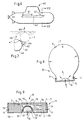
- FIG. 1 is a submarine 1 on its front and on its rear Deck top 2, 3 provided with storage spaces 4, 5 for modules 6 according to Figure 4.
- Each storage space 4, 5 has one or more corresponding to the storage space 4, 5 adapted, for example tubular modules 6, this module 6 or these modules 6 extend according to the length of the storage space 4.5.
- the upper side of deck 2 or 3 either has flaps (not shown) or predetermined breaking points 15 according to Figure 9 This ensures that when inflating the swimming bags 7 that can unfold outside of the submarine 1, as from Figure 3 emerges.
- the inflated swimming bags 7 lie close together or support each other, thereby creating a stable buoyancy configuration.
- the modules 6 can also be attached to the outside of the submarine or through Belts 41 ( Figure 7) can be held. Adhesive or Screw connections.
- the module 6 consists of a base plate 12 made of steel or Plastic, attached gas generator 16 according to the high-low pressure system, the bag 7 and a liquid-tight packing bag 8.
- the Sack 7 is with a differential piston valve 9 and an ignition 17, 18 (see also Figure 9) provided. This valve ensures that the pressure in the sack 7 is short remains above the external pressure. This ensures that a simple, light, portable, cheap material to use. This material leaves stow away well and is available as standard goods.
- the submarine 1 has a diving tank inside the bow 20 on. If the immersion tank 20 is damaged by external influences (Enemy action, collision with surface ships) is pushing out again of the penetrated ambient water in a simple manner by at least one of modules 6 to accomplish.
- the module 6 is on the bottom 21 of the Immersion tanks 20 arranged.
- the modules 6 are activated by appropriate sensors, that is to say controlled automatically or manually, and push the water out of the immersion tank 23.
- the modules 6 can be activated as a whole or selectively.
- a submersible 40 has a commercial or scientific design Purposes an external transport container fastened by straps 41 42 on both sides. At least one module 6 is in the transport container 42 integrated, the dash-dotted swimming bag 7 with a length inflates, which corresponds to the length of the transport container 42. The ignition trigger for the module 6 and also for opening a flap 44 of the transport container 42 takes place automatically or manually.
- a module 10 consists of a housing 11. This is structured in base plate 12, side walls 13 and cover plate 14 with predetermined breaking point 15.
- the gas generator 16 according to the high-low pressure principle consists of an ignition line 17, a lighter 18, a gas set 19 and one with holes 21 provided housing 22.
- the gas generator 16 is with the base plate 12 firmly connected.
- the sack 7 is folded in the housing 11 and is at 9 with the Side walls 13 firmly connected.
- the cover plate 14 closes with the side walls 13 waterproof. Attachments to watercraft are at 24 designated.
- the gas generator 16 is located in a watertight interior 31
- the inflated swimming bag according to FIG. 7, 7 has any suitable shape, such as a sphere or hose on.
- the swimming bag 7 consists of a gas-tight fabric of a known type, such as it is used on raft bags.
- the buoyancy aid described above is inexpensive, compact and has a light weight. Due to the modular structure of the buoyancy aid, the system is versatile and above all, it has the required functional reliability on.
- Module 6 can be installed in submarines wherever there is a buoyancy volume is useful. Such usable gaps exist between lines, Fuel tanks, drive units, internals and others.
Landscapes
- Engineering & Computer Science (AREA)
- Mechanical Engineering (AREA)
- Chemical & Material Sciences (AREA)
- Combustion & Propulsion (AREA)
- Ocean & Marine Engineering (AREA)
- Aviation & Aerospace Engineering (AREA)
- Filling Or Discharging Of Gas Storage Vessels (AREA)
Description
- Figur 1
- ein U-Boot in einer Seitenansicht,
- Figur 2
- das U-Boot nach Figur 1 in einer Ansicht von oben,
- Figur 3
- einen Querschnitt III-III nach Figur 1,
- Figur 4
- einen Modul,
- Figur 5
- einen Tauchtank eines U-Bootes,
- Figur 6
- ein Tauchboot,
- Figur 7
- einen Querschnitt VI-VI nach Figur 5,
- Figur 8
- einen aufgeblasenen Sack eines Moduls und
- Figur 9
- einen Modul mit gefaltetem Sack und Gasgenerator.
Bei einem Riß in der Außenhaut 27 erfolgt der Wassereintritt. Durch entsprechende Sensoren, also automatisch oder manuell gesteuert, werden die Module 6 aktiviert und drücken das Wasser aus dem Tauchtank 23 hinaus. Die Module 6 können insgesamt oder selektiv aktiviert werden.
Claims (9)
- Auftriebshilfe für Unterwasserfahrzeug in Seenot mit mindestens zwei Auftriebseinrichtungsmodule, bestehend aus einem Gasgenerator (16) zur Erzeugung von ungiftigem Gas, wenigstens einem aufblasbaren Schwimmsack (7) mit Überdruckventil (9) und
einer zu öffnenden Umhüllung (8, 10),
dadurch gekennzeichnet,
daß jeder Modul (6, 10) einen Gasgenerator (16), einen Schwimmsack (7) und eine Umhüllung (8, 11) aufweist. - Auftriebshilfe nach Anspruch 1,
dadurch gekennzeichnet,
daß der Gasgenerator (16) in einem, durch eine Bodenplatte (12) und dem Schwimmsack (7) gebildeten wasserdichten Innenraum (31) angeordnet ist. - Auftriebshilfe nach Anspruch 1,
dadurch gekennzeichnet,
daß die Umhüllung ein Gehäuse (11) mit Klappdeckel oder ein Gehäuse mit Sollbruchstelle (15) ist oder ein auftrennbarer Packsack (8) aus Kunststoff.. - Auftriebshilfe nach Anspruch 1,
dadurch gekennzeichnet,
daß ein wasserdichter Packsack (8) den Schwimmsack (7) umhüllt. - Auftriebshilfe nach Anspruch 1 zur Verwendung bei Tauchbooten, Unterseebooten,
dadurch gekennzeichnet,
daß das U-Boot (1) in nach außen zu öffnende Stauräumen (4,5) die Module (6,10) aufweist. - Auftriebshilfe nach Anspruch 1 zur Verwendung bei Tauchbooten, Unterseebooten,
dadurch gekennzeichnet,
daß in einem Tauchtank (20) wenigstens ein Modul (6,10) angeordnet ist. - Auftriebshilfe nach Anspruch 1,
dadurch gekennzeichnet,
daß ein Tauchtank (20) an seiner Innenwand (28) wenigstens einen Modul (6,10) aufweist. - Auftriebshilfe nach Anspruch 1 zur Verwendung bei Tauchbooten, Unterseebooten, wobei mit diesen beidseitig ein Transportbehälter verbunden ist,
dadurch gekennzeichnet,
daß der Transportbehälter (42) wenigstens einen Modul (6,10) enthält. - Auftriebshilfe nach Anspruch 1 zur Verwendung bei Tauchbooten, Unterseebooten,
dadurch gekennzeichnet,
daß wenigstens ein Modul (6) entweder an der Außenhaut (27) des Bootes (1,40) befestigt ist oder außen am Boot (1,40) gehalten ist, beispielsweise durch Gurte (41).
Applications Claiming Priority (2)
| Application Number | Priority Date | Filing Date | Title |
|---|---|---|---|
| DE19512753A DE19512753A1 (de) | 1995-04-05 | 1995-04-05 | Auftriebshilfe für Wasserfahrzeuge in Seenot |
| DE19512753 | 1995-04-05 |
Publications (2)
| Publication Number | Publication Date |
|---|---|
| EP0736450A1 EP0736450A1 (de) | 1996-10-09 |
| EP0736450B1 true EP0736450B1 (de) | 2000-06-28 |
Family
ID=7758857
Family Applications (1)
| Application Number | Title | Priority Date | Filing Date |
|---|---|---|---|
| EP96104303A Expired - Lifetime EP0736450B1 (de) | 1995-04-05 | 1996-03-19 | Auftriebshilfe für Wasserfahrzeuge in Seenot |
Country Status (3)
| Country | Link |
|---|---|
| EP (1) | EP0736450B1 (de) |
| DE (2) | DE19512753A1 (de) |
| TR (1) | TR199600245A2 (de) |
Cited By (3)
| Publication number | Priority date | Publication date | Assignee | Title |
|---|---|---|---|---|
| WO2004056649A1 (de) | 2002-12-21 | 2004-07-08 | Diehl Bgt Defence Gmbh & Co. Kg | Gasgenerator für auftriebssäcke von wasserfahrzeugen |
| KR20140138365A (ko) * | 2010-10-18 | 2014-12-04 | 대우조선해양 주식회사 | 무장 탑재를 위한 잠수함의 흘수 조정방법 |
| KR20180062888A (ko) * | 2016-12-01 | 2018-06-11 | 주식회사 한화 | 가스발생기와 메탈블레더를 이용한 비상용 메탈블레더 장치 |
Families Citing this family (11)
| Publication number | Priority date | Publication date | Assignee | Title |
|---|---|---|---|---|
| FR2762285B1 (fr) * | 1997-04-17 | 1999-06-25 | Rene Montoro | Dispositif anti-naufrage par effet de flotteurs et de ballons gonflables ou a expansion |
| DE19752499C2 (de) * | 1997-11-27 | 2000-06-29 | Diehl Stiftung & Co | Rettungssystem für Schiffe |
| DE19752498C2 (de) * | 1997-11-27 | 2002-04-18 | Diehl Stiftung & Co | Auftriebshilfe für Wasserfahrzeuge |
| DE19806101C2 (de) * | 1998-02-14 | 2001-05-10 | Diehl Stiftung & Co | Druckausgleich für Auftriebssäcke im Wasser |
| DE10019578A1 (de) | 2000-04-20 | 2002-02-14 | Diehl Munitionssysteme Gmbh | Auftriebsmodul für den Unterwassereinsatz |
| FR2808253A1 (fr) * | 2000-04-26 | 2001-11-02 | Jean Francois Vincent | Saillie securitaire nautique |
| ES2261997T3 (es) * | 2002-12-21 | 2006-11-16 | DIEHL BGT DEFENCE GMBH & CO.KG | Generador de gas para sacos de empuje ascensional de vehiculos acuaticos. |
| RU2525248C2 (ru) * | 2009-08-14 | 2014-08-10 | Арчимедс Пти Лтд | Система обеспечения плавучести |
| UA77085U (uk) * | 2012-07-26 | 2013-01-25 | Аркадій Олександрович Мартіросов | Спосіб підняття затонулих суден |
| DE102016220949B3 (de) | 2016-10-25 | 2018-04-19 | Trumpf Laser- Und Systemtechnik Gmbh | Verfahren zum schnellen Inertisieren einer Kammer einer Maschine zur additiven Fertigung von Bauteilen und zugehörige Maschine |
| CN111301636B (zh) * | 2020-03-14 | 2021-03-23 | 自然资源部第二海洋研究所 | 一种中小型浮力式海洋打捞设备 |
Family Cites Families (6)
| Publication number | Priority date | Publication date | Assignee | Title |
|---|---|---|---|---|
| CH154689A (fr) * | 1931-10-19 | 1932-05-15 | Landry William Fils | Dispositif applicable à un sous-marin et déstiné à son renflouage en cas d'accident. |
| DK131716C (da) * | 1974-01-31 | 1976-02-02 | B K Henriksen | Skib med oppustelige sekke anbragt i nicher i skibssiderne |
| DE3338375A1 (de) * | 1983-10-21 | 1985-05-02 | Lothar 2391 Wees Köhler | Rumpf fuer eine jacht mit einrichtungen zur aufrechterhaltung der schwimmfaehigkeit bei einer havarie |
| DE3414646A1 (de) * | 1984-04-18 | 1985-10-31 | Bundesrepublik Deutschland, vertreten durch den Bundesminister der Verteidigung, dieser vertreten durch den Präsidenten des Bundesamtes für Wehrtechnik und Beschaffung, 5400 Koblenz | Bergeeinrichtung fuer u-boote |
| JPS61238587A (ja) * | 1985-04-16 | 1986-10-23 | Mitsubishi Heavy Ind Ltd | 潜水物体用浮上装置 |
| EP0487527A1 (de) * | 1989-05-11 | 1992-06-03 | 824328 Ontario Limited | Rettungsschwimmvorrichtung für wasserfahrzeuge |
-
1995
- 1995-04-05 DE DE19512753A patent/DE19512753A1/de not_active Withdrawn
-
1996
- 1996-03-19 EP EP96104303A patent/EP0736450B1/de not_active Expired - Lifetime
- 1996-03-19 DE DE59605477T patent/DE59605477D1/de not_active Expired - Fee Related
- 1996-03-27 TR TR96/00245A patent/TR199600245A2/xx unknown
Cited By (3)
| Publication number | Priority date | Publication date | Assignee | Title |
|---|---|---|---|---|
| WO2004056649A1 (de) | 2002-12-21 | 2004-07-08 | Diehl Bgt Defence Gmbh & Co. Kg | Gasgenerator für auftriebssäcke von wasserfahrzeugen |
| KR20140138365A (ko) * | 2010-10-18 | 2014-12-04 | 대우조선해양 주식회사 | 무장 탑재를 위한 잠수함의 흘수 조정방법 |
| KR20180062888A (ko) * | 2016-12-01 | 2018-06-11 | 주식회사 한화 | 가스발생기와 메탈블레더를 이용한 비상용 메탈블레더 장치 |
Also Published As
| Publication number | Publication date |
|---|---|
| DE59605477D1 (de) | 2000-08-03 |
| TR199600245A2 (tr) | 1996-12-21 |
| DE19512753A1 (de) | 1996-10-10 |
| EP0736450A1 (de) | 1996-10-09 |
Similar Documents
| Publication | Publication Date | Title |
|---|---|---|
| US6080027A (en) | Flotation device | |
| EP0736450A1 (de) | Auftriebshilfe für Wasserfahrzeuge in Seenot | |
| US4227477A (en) | Inflatable barge | |
| CN101715409A (zh) | 用于撤离目的的可漂浮设备 | |
| KR20150030785A (ko) | 고속 수상 능력을 갖는 범용 잠수함 | |
| US4887541A (en) | Deployable flotation device | |
| US3696453A (en) | Life saving equipment | |
| US3131406A (en) | Vessels having a collapsible bottom and inflatable surround | |
| KR20150128631A (ko) | 침몰 방지 선박용 에어백 장치 | |
| CN109050819A (zh) | 一种水中航行器的自救系统 | |
| WO2013114184A1 (en) | Anti-sinking emergency device by automatic ejection and inflation of balloons | |
| CN106809157A (zh) | 交通工具应急漂浮装置 | |
| DE2462606B1 (de) | Rettungsboje | |
| US2686323A (en) | Airborne lifeboat | |
| DE19752498C2 (de) | Auftriebshilfe für Wasserfahrzeuge | |
| EP2045182A2 (de) | Fluidverdrängungskörper für ein Notschwimmwerk eines Wasserahrzeugs | |
| DE19610417B4 (de) | Sicherungssystem für die in einem Laderaum eines Wasserfahrzeuges befindliche Ladung | |
| DE102013002170A1 (de) | Rettungssystem für passagierschiffe | |
| GB2224979A (en) | Emergency buoyancy system | |
| DE3105427A1 (de) | Rettungsgeraet fuer boote | |
| US5003908A (en) | Control and limiting of oil spills from an ocean going tanker | |
| RU2081783C1 (ru) | Спасательное устройство подводной лодки | |
| US20180244358A1 (en) | Sponge ballast system for inflatable rafts | |
| DE3338375A1 (de) | Rumpf fuer eine jacht mit einrichtungen zur aufrechterhaltung der schwimmfaehigkeit bei einer havarie | |
| DE3900572C2 (de) |
Legal Events
| Date | Code | Title | Description |
|---|---|---|---|
| PUAI | Public reference made under article 153(3) epc to a published international application that has entered the european phase |
Free format text: ORIGINAL CODE: 0009012 |
|
| 17P | Request for examination filed |
Effective date: 19960727 |
|
| AK | Designated contracting states |
Kind code of ref document: A1 Designated state(s): DE FR GB IT |
|
| RAP1 | Party data changed (applicant data changed or rights of an application transferred) |
Owner name: DIEHL STIFTUNG & CO. |
|
| 17Q | First examination report despatched |
Effective date: 19981007 |
|
| GRAG | Despatch of communication of intention to grant |
Free format text: ORIGINAL CODE: EPIDOS AGRA |
|
| GRAG | Despatch of communication of intention to grant |
Free format text: ORIGINAL CODE: EPIDOS AGRA |
|
| GRAH | Despatch of communication of intention to grant a patent |
Free format text: ORIGINAL CODE: EPIDOS IGRA |
|
| GRAH | Despatch of communication of intention to grant a patent |
Free format text: ORIGINAL CODE: EPIDOS IGRA |
|
| GRAA | (expected) grant |
Free format text: ORIGINAL CODE: 0009210 |
|
| AK | Designated contracting states |
Kind code of ref document: B1 Designated state(s): DE FR GB IT |
|
| REF | Corresponds to: |
Ref document number: 59605477 Country of ref document: DE Date of ref document: 20000803 |
|
| GBT | Gb: translation of ep patent filed (gb section 77(6)(a)/1977) |
Effective date: 20000726 |
|
| ITF | It: translation for a ep patent filed | ||
| ET | Fr: translation filed | ||
| PLBE | No opposition filed within time limit |
Free format text: ORIGINAL CODE: 0009261 |
|
| STAA | Information on the status of an ep patent application or granted ep patent |
Free format text: STATUS: NO OPPOSITION FILED WITHIN TIME LIMIT |
|
| 26N | No opposition filed | ||
| REG | Reference to a national code |
Ref country code: GB Ref legal event code: IF02 |
|
| PGFP | Annual fee paid to national office [announced via postgrant information from national office to epo] |
Ref country code: GB Payment date: 20070328 Year of fee payment: 12 |
|
| PGFP | Annual fee paid to national office [announced via postgrant information from national office to epo] |
Ref country code: DE Payment date: 20070516 Year of fee payment: 12 |
|
| PGFP | Annual fee paid to national office [announced via postgrant information from national office to epo] |
Ref country code: IT Payment date: 20070614 Year of fee payment: 12 |
|
| PGFP | Annual fee paid to national office [announced via postgrant information from national office to epo] |
Ref country code: FR Payment date: 20070228 Year of fee payment: 12 |
|
| GBPC | Gb: european patent ceased through non-payment of renewal fee |
Effective date: 20080319 |
|
| REG | Reference to a national code |
Ref country code: FR Ref legal event code: ST Effective date: 20081125 |
|
| PG25 | Lapsed in a contracting state [announced via postgrant information from national office to epo] |
Ref country code: DE Free format text: LAPSE BECAUSE OF NON-PAYMENT OF DUE FEES Effective date: 20081001 |
|
| PG25 | Lapsed in a contracting state [announced via postgrant information from national office to epo] |
Ref country code: FR Free format text: LAPSE BECAUSE OF NON-PAYMENT OF DUE FEES Effective date: 20080331 |
|
| PG25 | Lapsed in a contracting state [announced via postgrant information from national office to epo] |
Ref country code: GB Free format text: LAPSE BECAUSE OF NON-PAYMENT OF DUE FEES Effective date: 20080319 |
|
| PG25 | Lapsed in a contracting state [announced via postgrant information from national office to epo] |
Ref country code: IT Free format text: LAPSE BECAUSE OF NON-PAYMENT OF DUE FEES Effective date: 20080319 |