EP0736322B1 - Apparatus for introducing a gas into a liquid - Google Patents
Apparatus for introducing a gas into a liquid Download PDFInfo
- Publication number
- EP0736322B1 EP0736322B1 EP19960400583 EP96400583A EP0736322B1 EP 0736322 B1 EP0736322 B1 EP 0736322B1 EP 19960400583 EP19960400583 EP 19960400583 EP 96400583 A EP96400583 A EP 96400583A EP 0736322 B1 EP0736322 B1 EP 0736322B1
- Authority
- EP
- European Patent Office
- Prior art keywords
- turbine
- vanes
- gas
- diffusion
- radial
- Prior art date
- Legal status (The legal status is an assumption and is not a legal conclusion. Google has not performed a legal analysis and makes no representation as to the accuracy of the status listed.)
- Expired - Lifetime
Links
Images

Classifications
-
- C—CHEMISTRY; METALLURGY
- C02—TREATMENT OF WATER, WASTE WATER, SEWAGE, OR SLUDGE
- C02F—TREATMENT OF WATER, WASTE WATER, SEWAGE, OR SLUDGE
- C02F3/00—Biological treatment of water, waste water, or sewage
- C02F3/02—Aerobic processes
- C02F3/12—Activated sludge processes
- C02F3/20—Activated sludge processes using diffusers
- C02F3/205—Moving, e.g. rotary, diffusers; Stationary diffusers with moving, e.g. rotary, distributors
-
- B—PERFORMING OPERATIONS; TRANSPORTING
- B01—PHYSICAL OR CHEMICAL PROCESSES OR APPARATUS IN GENERAL
- B01F—MIXING, e.g. DISSOLVING, EMULSIFYING OR DISPERSING
- B01F27/00—Mixers with rotary stirring devices in fixed receptacles; Kneaders
- B01F27/05—Stirrers
- B01F27/11—Stirrers characterised by the configuration of the stirrers
- B01F27/111—Centrifugal stirrers, i.e. stirrers with radial outlets; Stirrers of the turbine type, e.g. with means to guide the flow
-
- B—PERFORMING OPERATIONS; TRANSPORTING
- B01—PHYSICAL OR CHEMICAL PROCESSES OR APPARATUS IN GENERAL
- B01F—MIXING, e.g. DISSOLVING, EMULSIFYING OR DISPERSING
- B01F23/00—Mixing according to the phases to be mixed, e.g. dispersing or emulsifying
- B01F23/20—Mixing gases with liquids
- B01F23/23—Mixing gases with liquids by introducing gases into liquid media, e.g. for producing aerated liquids
- B01F23/233—Mixing gases with liquids by introducing gases into liquid media, e.g. for producing aerated liquids using driven stirrers with completely immersed stirring elements
- B01F23/2331—Mixing gases with liquids by introducing gases into liquid media, e.g. for producing aerated liquids using driven stirrers with completely immersed stirring elements characterised by the introduction of the gas along the axis of the stirrer or along the stirrer elements
- B01F23/23314—Mixing gases with liquids by introducing gases into liquid media, e.g. for producing aerated liquids using driven stirrers with completely immersed stirring elements characterised by the introduction of the gas along the axis of the stirrer or along the stirrer elements through a hollow stirrer element
-
- B—PERFORMING OPERATIONS; TRANSPORTING
- B01—PHYSICAL OR CHEMICAL PROCESSES OR APPARATUS IN GENERAL
- B01F—MIXING, e.g. DISSOLVING, EMULSIFYING OR DISPERSING
- B01F27/00—Mixers with rotary stirring devices in fixed receptacles; Kneaders
- B01F27/80—Mixers with rotary stirring devices in fixed receptacles; Kneaders with stirrers rotating about a substantially vertical axis
- B01F27/81—Mixers with rotary stirring devices in fixed receptacles; Kneaders with stirrers rotating about a substantially vertical axis the stirrers having central axial inflow and substantially radial outflow
-
- B—PERFORMING OPERATIONS; TRANSPORTING
- B01—PHYSICAL OR CHEMICAL PROCESSES OR APPARATUS IN GENERAL
- B01F—MIXING, e.g. DISSOLVING, EMULSIFYING OR DISPERSING
- B01F23/00—Mixing according to the phases to be mixed, e.g. dispersing or emulsifying
- B01F23/20—Mixing gases with liquids
- B01F23/23—Mixing gases with liquids by introducing gases into liquid media, e.g. for producing aerated liquids
- B01F23/233—Mixing gases with liquids by introducing gases into liquid media, e.g. for producing aerated liquids using driven stirrers with completely immersed stirring elements
- B01F23/2331—Mixing gases with liquids by introducing gases into liquid media, e.g. for producing aerated liquids using driven stirrers with completely immersed stirring elements characterised by the introduction of the gas along the axis of the stirrer or along the stirrer elements
- B01F23/23311—Mixing gases with liquids by introducing gases into liquid media, e.g. for producing aerated liquids using driven stirrers with completely immersed stirring elements characterised by the introduction of the gas along the axis of the stirrer or along the stirrer elements through a hollow stirrer axis
-
- B—PERFORMING OPERATIONS; TRANSPORTING
- B01—PHYSICAL OR CHEMICAL PROCESSES OR APPARATUS IN GENERAL
- B01F—MIXING, e.g. DISSOLVING, EMULSIFYING OR DISPERSING
- B01F23/00—Mixing according to the phases to be mixed, e.g. dispersing or emulsifying
- B01F23/20—Mixing gases with liquids
- B01F23/23—Mixing gases with liquids by introducing gases into liquid media, e.g. for producing aerated liquids
- B01F23/233—Mixing gases with liquids by introducing gases into liquid media, e.g. for producing aerated liquids using driven stirrers with completely immersed stirring elements
- B01F23/2335—Mixing gases with liquids by introducing gases into liquid media, e.g. for producing aerated liquids using driven stirrers with completely immersed stirring elements characterised by the direction of introduction of the gas relative to the stirrer
- B01F23/23352—Mixing gases with liquids by introducing gases into liquid media, e.g. for producing aerated liquids using driven stirrers with completely immersed stirring elements characterised by the direction of introduction of the gas relative to the stirrer the gas moving perpendicular to the axis of rotation
-
- B—PERFORMING OPERATIONS; TRANSPORTING
- B01—PHYSICAL OR CHEMICAL PROCESSES OR APPARATUS IN GENERAL
- B01F—MIXING, e.g. DISSOLVING, EMULSIFYING OR DISPERSING
- B01F23/00—Mixing according to the phases to be mixed, e.g. dispersing or emulsifying
- B01F23/20—Mixing gases with liquids
- B01F23/23—Mixing gases with liquids by introducing gases into liquid media, e.g. for producing aerated liquids
- B01F23/233—Mixing gases with liquids by introducing gases into liquid media, e.g. for producing aerated liquids using driven stirrers with completely immersed stirring elements
- B01F23/2336—Mixing gases with liquids by introducing gases into liquid media, e.g. for producing aerated liquids using driven stirrers with completely immersed stirring elements characterised by the location of the place of introduction of the gas relative to the stirrer
- B01F23/23364—Mixing gases with liquids by introducing gases into liquid media, e.g. for producing aerated liquids using driven stirrers with completely immersed stirring elements characterised by the location of the place of introduction of the gas relative to the stirrer the gas being introduced between the stirrer elements
-
- Y—GENERAL TAGGING OF NEW TECHNOLOGICAL DEVELOPMENTS; GENERAL TAGGING OF CROSS-SECTIONAL TECHNOLOGIES SPANNING OVER SEVERAL SECTIONS OF THE IPC; TECHNICAL SUBJECTS COVERED BY FORMER USPC CROSS-REFERENCE ART COLLECTIONS [XRACs] AND DIGESTS
- Y02—TECHNOLOGIES OR APPLICATIONS FOR MITIGATION OR ADAPTATION AGAINST CLIMATE CHANGE
- Y02W—CLIMATE CHANGE MITIGATION TECHNOLOGIES RELATED TO WASTEWATER TREATMENT OR WASTE MANAGEMENT
- Y02W10/00—Technologies for wastewater treatment
- Y02W10/10—Biological treatment of water, waste water, or sewage
Definitions
- the present invention relates to a device intended for the introduction of a gas within a static or moving liquid mass in order to achieve its solution in this liquid, this device being immersed in this liquid mass.
- Such devices which are generally in the form of turbines submerged driven by an electric motor and under the propeller of which opens the end of a gas inlet pipe, are used in particular in processes for the biological purification of effluents or waste water where they are used to carry out an intense introduction of air or oxygen into the raw effluent, this oxygen or this air ensuring direct oxidation of the effluent and allowing aerobic bacteria to live and multiply.
- These same devices can also be applied to degreasing and de-oiling in pretreatment in waste water treatment plants, by introducing air into the mass of waste water, in the form of very fine dispersed bubbles, this air promoting collection of fat and foam on the surface.
- Known devices include a drive motor, a wind box, a gas intake manifold and a radial diffusion turbine which is coupled to a brewing turbine, these two turbines being immersed in the liquid mass and the gas, for example pressurized air or not, being brought to the center of the turbine diffusion and distributed between the blades of the latter.
- US-A-5,160,459 describes a fluid mixer for especially to the chemical industry which includes a turbine unique consisting of a double tray on which are implanted rectangular blades, internal fins being arranged between the two trays to facilitate the air flow.
- DE-C-0 828 100 describes a mixer rotor, sucking in two axial directions and in which the openings in the same suction chamber and in a rotor chamber common to the two openings.
- the rotor has inclined, shaped blades curvilinear, some being shorter than the others.
- the present invention proposes to bring improvements, in particular in order to improve dissemination by creating conditions for obtaining very fine bubbles of gases with optimal efficiency of diffusion turbines and and avoiding any obstruction that could arise from the presence of solid particles in the liquid mass to be treated.
- the subject of this invention is a device to introduce a gas into a liquid which includes a drive motor, a wind box, a manifold gas intake, a brewing turbine and a radial diffusion coupled to said stirring turbine, the two turbines being immersed in the liquid mass and the gas being brought to the center of the diffusion turbine and distributed between the fins of the latter,
- said turbine diffusion comprises a plurality of radial fins extending to the brewing turbine shaft, alternating with non-extending radial fins up to tree audit to leave a clear interval between said tree and the respective internal edges of said radial fins, these two sets of fins being fixed under a plate driven in rotation by said shaft, in that said radial blades of the turbine diffusion laterally extend the blades of the brewing turbine, even in a vacuum zone relative behind the turbine, and in that discharge fins are provided, mounted above of the tray receiving, under its underside, said fins of the radial diffusion turbine.
- the expansion of the liquid is promoted pressurized and, therefore, micro-bubble diffusion in the liquid mass.
- the latter is thus more homogeneous because it is caught in the upward flow generated by the blades of the brewing turbine extended by the fins of the diffusion turbine radial.
- the two turbines are mounted under a hydraulic plate on which are mounted the engine, the wind box and the gas intake manifold.
- valve in particular a ball valve, placed on the gas intake pipe in order to regulate the gas flow admitted into the turbine.
- the device according to this invention is of the type which includes a drive motor 16 mounted on a wind box 18 in which opens the end of a gas intake manifold 20.
- This engine drives a set of turbines via its rotation shaft 14.
- This assembly comprises a radial diffusion turbine 12 coupled to a turbine mixing 10.
- the set of 10-12 turbines is held by keying at the end of the shaft 14 in a hub 32.
- the gas for example pressurized air or not, is brought to the center of the turbine diffusion 12 between the fins of the latter as indicated by the arrows on Figure 1.
- the set of turbines thus described is immersed within the mass liquid to be aerated and stirred.
- each radial fin such as 24 or 26 and each blade of the stirring turbine 10 have a common edge. Thanks to this characteristic, we promote relaxation pressurized liquid and therefore the diffusion of micro-bubbles within the liquid mass. The latter is therefore more homogeneous because it is caught in the flow rising which is generated by the blades of the stirring turbine 10 which are extended by the fins 24, 26 of the radial diffusion turbine 12.
- the height of the blades of the stirring turbine 10 is chosen as a function of desired intensity of brewing.
- the set of turbines is mounted under a hydraulic plate 22 on which are fixed the wind box 18, the motor 16 and the gas intake pipe 20.
- fins discharge such as 28 (FIGS. 1 and 2) which are mounted above the plate 36 on which are mounted, under its underside, the two types of radial fins 24, 26 of the diffusion turbine 12.
- a valve in particular a ball valve 30, placed on the gas intake pipe 20 in order to allow adjustment of the volume of air admitted into the device, allowing thus an empirical adjustment of the air / solid ratio, i.e. the weight of air released (in kilos) per kilogram of suspended matter.
- the supply of gas for example air or oxygen can be performed via a compressor supplying the intake manifold gas 20, in case large flows are required. Note that this feature brings great flexibility as it allows to use simultaneously the compressor and the turbines during peak periods and turbines only outside such periods.
- the device object of the invention makes it possible to simultaneously carry out oxygenation by diffusion of bubbles very fine air or oxygen through a liquid mass and mixing homogeneous of this mass.
- the device according to the invention can be applied to degreasing and deoiling waste effluents. It is then immersed in the liquid mass so that the air released into this mass, in the form of very fine bubbles dispersed within liquid mass, promotes the flotation of fat and foam on the surface ; the device then has the advantage of also allowing mixing of the bottom without agitation of the surface likely to disturb the film or the layer of flotation materials.
- the device according to the invention can also be used in a biological water treatment plant using activated sludge. He is immersed in the liquid mass and supplied preferably with compressed air (or oxygen). II then simultaneously ensures oxygenation of the effluent allowing the aerobic bacteria to live and multiply, thanks to the formation of fine bubbles air (or oxygen) within the liquid mass and a mixing of this same liquid mass to keep the activated sludge in suspension and to ensure the homogeneity of the mixture.
- compressed air or oxygen
Abstract
Description
La présente invention est relative à un dispositif destiné à l'introduction d'un gaz au sein d'une masse liquide statique ou en mouvement en vue d'en réaliser la solution dans ce liquide, ce dispositif étant immergé dans cette masse liquide.The present invention relates to a device intended for the introduction of a gas within a static or moving liquid mass in order to achieve its solution in this liquid, this device being immersed in this liquid mass.
De tels dispositifs, qui se présentent généralement sous la forme de turbines immergées entraínées par un moteur électrique et sous l'hélice desquelles débouche l'extrémité d'une conduite d'admission de gaz, sont utilisés en particulier dans des procédés d'épuration biologique d'effluents ou d'eaux résiduaires où ils servent à effectuer une introduction intense d'air ou d'oxygène dans l'effluent brut, cet oxygène ou cet air assurant une oxydation directe de l'effluent et permettant aux bactéries aérobies de vivre et de se multiplier. Ces mêmes dispositifs peuvent également être appliqués au dégraissage et déshuilage en prétraitement dans les stations d'épuration d'eaux résiduaires, en introduisant de l'air dans la masse de l'eau résiduaire, sous la forme de très fines bulles dispersées, cet air favorisant le rassemblement des graisses et écumes en surface.Such devices, which are generally in the form of turbines submerged driven by an electric motor and under the propeller of which opens the end of a gas inlet pipe, are used in particular in processes for the biological purification of effluents or waste water where they are used to carry out an intense introduction of air or oxygen into the raw effluent, this oxygen or this air ensuring direct oxidation of the effluent and allowing aerobic bacteria to live and multiply. These same devices can also be applied to degreasing and de-oiling in pretreatment in waste water treatment plants, by introducing air into the mass of waste water, in the form of very fine dispersed bubbles, this air promoting collection of fat and foam on the surface.
On connaít déjà des dispositifs qui permettent d'effectuer simultanément une diffusion gazeuse au sein de la masse liquide à aérer et un brassage de cette même masse liquide, ce brassage pouvant être plus ou moins violent en fonction des conditions d'application et d'utilisation de tels dispositifs.We already know devices that allow to simultaneously perform a gas diffusion within the liquid mass to be aerated and a mixing thereof liquid mass, this mixing can be more or less violent depending on the conditions of application and use of such devices.
Les dispositifs connus comportent un moteur d'entraínement, une boíte à vent, une tubulure de prise de gaz et une turbine de diffusion radiale qui est accouplée à une turbine de brassage, ces deux turbines étant immergées dans la masse liquide et le gaz, par exemple de l'air pressurisé ou non, étant amené au centre de la turbine de diffusion et distribué entre les pales de cette dernière. Known devices include a drive motor, a wind box, a gas intake manifold and a radial diffusion turbine which is coupled to a brewing turbine, these two turbines being immersed in the liquid mass and the gas, for example pressurized air or not, being brought to the center of the turbine diffusion and distributed between the blades of the latter.
Un exemple de réalisation de ces dispositifs connus est décrit par FR-A-2 293 235.An exemplary embodiment of these known devices is described by FR-A-2 293 235.
US-A-5 160 459 décrit un mélangeur de fluides destiné notamment à l'industrie chimique qui comporte une turbine unique constituée d'un double plateau sur lequel sont implantées des pales rectangulaires, des ailettes internes étant disposées entre les deux plateaux afin de faciliter le flux d'air.US-A-5,160,459 describes a fluid mixer for especially to the chemical industry which includes a turbine unique consisting of a double tray on which are implanted rectangular blades, internal fins being arranged between the two trays to facilitate the air flow.
DE-C-0 828 100 décrit un rotor de mélangeur, aspirant dans deux directions axiales et dans lequel les ouvertures d'aspiration débouchent dans la même chambre d'aspiration et dans une chambre de rotor commune aux deux ouvertures. Le rotor comporte des aubes inclinées, de forme curviligne, certaines étant plus courtes que les autres. DE-C-0 828 100 describes a mixer rotor, sucking in two axial directions and in which the openings in the same suction chamber and in a rotor chamber common to the two openings. The rotor has inclined, shaped blades curvilinear, some being shorter than the others.
Partant de cet état de la technique, la présente invention se propose d'apporter des perfectionnements, notamment dans le but d'améliorer la diffusion en créant des conditions permettant d'obtenir de très fines bulles de gaz avec un rendement optimal des turbines de diffusion et de brassage et en évitant toute obstruction pouvant découler de la présence de particules solides dans la masse liquide à traiter.Starting from this state of the art, the present invention proposes to bring improvements, in particular in order to improve dissemination by creating conditions for obtaining very fine bubbles of gases with optimal efficiency of diffusion turbines and and avoiding any obstruction that could arise from the presence of solid particles in the liquid mass to be treated.
En conséquence, cette invention a pour objet un dispositif pour introduire un gaz dans un liquide qui comprend un moteur d'entraínement, une boíte à vent, une tubulure de prise de gaz, une turbine de brassage et une turbine de diffusion radiale accouplée à ladite turbine de brassage, les deux turbines étant immergées dans la masse liquide et le gaz étant amené au centre de la turbine de diffusion et distribué entre les ailettes de cette dernière, ce dispositif étant caractérisé en ce que ladite turbine de diffusion comporte une pluralité d'ailettes radiales se prolongeant jusqu'à l'arbre de la turbine de brassage, alternées avec des ailettes radiales ne se prolongeant pas jusqu'audit arbre afin de laisser un intervalle dégagé entre ledit arbre et les arêtes respectives internes desdites ailettes radiales, ces deux jeux d'ailettes étant fixés sous un plateau entraíné en rotation par ledit arbre, en ce que lesdites ailettes radiales de la turbine de diffusion prolongent latéralement les pales de la turbine de brassage, jusque dans une zone de dépression relative située en arrière de la turbine, et en ce que l'on prévoit des ailettes de décharge, montées au-dessus du plateau recevant, sous sa face inférieure, lesdites ailettes de la turbine de diffusion radiale.Consequently, the subject of this invention is a device to introduce a gas into a liquid which includes a drive motor, a wind box, a manifold gas intake, a brewing turbine and a radial diffusion coupled to said stirring turbine, the two turbines being immersed in the liquid mass and the gas being brought to the center of the diffusion turbine and distributed between the fins of the latter, this device being characterized in that said turbine diffusion comprises a plurality of radial fins extending to the brewing turbine shaft, alternating with non-extending radial fins up to tree audit to leave a clear interval between said tree and the respective internal edges of said radial fins, these two sets of fins being fixed under a plate driven in rotation by said shaft, in that said radial blades of the turbine diffusion laterally extend the blades of the brewing turbine, even in a vacuum zone relative behind the turbine, and in that discharge fins are provided, mounted above of the tray receiving, under its underside, said fins of the radial diffusion turbine.
Grâce à l'invention, on favorise la détente du liquide pressurisé et, par conséquent, la diffusion micro-bulles dans la masse liquide. Cette dernière est ainsi plus homogène car elle est prise dans le flux ascendant engendré par les pales de la turbine de brassage prolongées par les ailettes de la turbine de difffusion radiale. Selon l'invention, les deux turbines sont montées sous un plateau hydraulique sur lequel sont montés le moteur, la boíte à vent et la tubulure de prise de gaz.Thanks to the invention, the expansion of the liquid is promoted pressurized and, therefore, micro-bubble diffusion in the liquid mass. The latter is thus more homogeneous because it is caught in the upward flow generated by the blades of the brewing turbine extended by the fins of the diffusion turbine radial. According to the invention, the two turbines are mounted under a hydraulic plate on which are mounted the engine, the wind box and the gas intake manifold.
Selon une autre caractéristique du dispositif objet de l'invention, on prévoit une vanne, notamment à boisseau, placée sur la tubulure de prise de gaz afin de régler le débit de gaz admis dans la turbine.According to another characteristic of the device which is the subject of the invention, provision is made for valve, in particular a ball valve, placed on the gas intake pipe in order to regulate the gas flow admitted into the turbine.
D'autres caractéristiques et avantages de la présente invention ressortiront de la description faite ci-après d'un exemple de réalisation non limitatif, en référence aux dessins annexés sur lesquels :
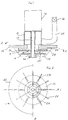
- la figure 1 est une vue schématique en coupe selon 1-1 de la figure 2 illustrant un mode de réalisation préféré du dispositif objet de l'invention ;
- la figure 2 est une vue en coupe selon 2-2 de la figure 1 ;
- la figure 3 est une vue partielle représentant uniquement les deux turbines accouplées en une coupe selon 3-3 de la figure 4 ;
- la figure 4 est une vue en plan de la figure 3 et ;
- la figure 5 est une vue en coupe selon 5-5 de la figure 3.
- Figure 1 is a schematic sectional view along 1-1 of Figure 2 illustrating a preferred embodiment of the device object of the invention;
- Figure 2 is a sectional view along 2-2 of Figure 1;
- Figure 3 is a partial view showing only the two turbines coupled in a section along 3-3 of Figure 4;
- Figure 4 is a plan view of Figure 3 and;
- FIG. 5 is a sectional view along 5-5 of FIG. 3.
En se référant aux dessins, on voit que le dispositif selon cette invention est du type
qui comprend un moteur d'entraínement 16 monté sur une boíte à vent 18 dans
laquelle débouche l'extrémité d'une tubulure de prise de gaz 20. Ce moteur entraíne
un ensemble de turbines par l'intermédiaire de son arbre de rotation 14. Cet
ensemble comporte une turbine de diffusion radiale 12 accouplée à une turbine de
brassage 10. Comme on le voit plus particulièrement sur la figure 1, l'ensemble de
turbines 10-12 est maintenu par clavetage à l'extrémité de l'arbre 14 dans un moyeu
32. Le gaz, par exemple de l'air pressurisé ou non est amené au centre de la turbine
de diffusion 12 entre les ailettes de cette dernière comme l'indiquent les flèches sur
la figure 1. L'ensemble de turbines ainsi décrit est immergé au sein de la masse
liquide devant être aérée et brassée.Referring to the drawings, it can be seen that the device according to this invention is of the type
which includes a
Selon l'invention, la turbine de diffusion radiale 12 comporte deux types d'ailettes régulièrement disposées sous un plateau 36 au centre duquel est ménagée une ouverture 38 pour l'admission du gaz amené par la tubulure 20. Ces ailettes sont les suivantes :
- une pluralité d'ailettes radiales de grande longueur désignées par la
référence 24 qui s'étendent depuis lemoyeu 32 de l'ensemble des turbines jusqu'à la périphérie de cet ensemble et ; - une pluralité d'ailettes radiales de longueur plus faible 26 qui ne se prolongent pas
jusqu'au moyeu 32 ainsi qu'on peut le voir sur les figures 3 et 4. Ces
ailettes 26 sont alternées avec lesailettes 24.
- a plurality of very long radial fins designated by the
reference 24 which extend from thehub 32 of the set of turbines to the periphery of this set and; - a plurality of radial fins of
shorter length 26 which do not extend to thehub 32 as can be seen in FIGS. 3 and 4. Thesefins 26 are alternated with thefins 24.
Grâce à cette disposition caractéristique de la présente invention, on laisse un
intervalle dégagé entre le moyeu 32 de la turbine et donc, l'arbre 14 du moteur, et
les arêtes internes 26' des ailettes 26. Par ailleurs, l'expérience a démontré que le
choix de ces deux types d'ailettes permettait d'obtenir la formation de micro-bulles
gazeuses à l'extrémité 26" des ailettes, et cela sur une ailette sur deux, par suite de
la détente du liquide pressurisé à cet endroit.Thanks to this characteristic arrangement of the present invention, a
clear interval between the
Ainsi qu'on le voit clairement sur les figures 1 et 3, les ailettes radiales 24 et 26 de la
turbine de diffusion 12 prolongent latéralement les pales de la turbine de brassage
10, jusqu'à une zone de dépression (relative) située en arrière de la turbine. Les
pales de la turbine de brassage 10 sont fixées sur un plateau 36 dans lequel est
ménagé le moyeu 32 recevant l'extrémité de l'arbre d'entraínement 14. Ainsi, chaque
ailette radiale telle que 24 ou 26 et chaque pale de la turbine de brassage 10
présentent une arête commune. Grâce à cette caractéristique, on favorise la détente
du liquide pressurisé et par conséquent, la diffusion des micro-bulles au sein de la
masse liquide. Cette dernière est donc plus homogène car elle est prise dans le flux
ascendant qui est engendré par les pales de la turbine de brassage 10 qui sont
prolongées par les ailettes 24, 26 de la turbine de diffusion radiale 12.As can be clearly seen in Figures 1 and 3, the
La hauteur des pales de la turbine de brassage 10 est choisie en fonction de
l'intensité désirée du brassage.The height of the blades of the stirring
L'ensemble de turbines est monté sous un plateau hydraulique 22 sur lequel sont
fixés la boíte à vent 18, le moteur 16 et la tubulure de prise de gaz 20.The set of turbines is mounted under a
Selon l'invention, et pour faciliter le nettoyage des turbines en éliminant les
particules qui se déposent à l'arrière de celles-ci, on prévoit des ailettes de
décharge telles que 28 (figure 1 et 2) qui sont montées au dessus du plateau 36 sur
lequel sont montées, sous sa face inférieure, les deux types d'ailettes radiales 24,
26 de la turbine de diffusion 12.According to the invention, and to facilitate the cleaning of the turbines by eliminating the
particles that settle on the back of them, there are fins
discharge such as 28 (FIGS. 1 and 2) which are mounted above the
On sait que la séparation effective solide-liquide et la concentration des matières
séparées dépendent du dégagement suffisant des bulles d'air par rapport aux
matières solides. Lors d'une application du dispositif selon l'invention à la
séparation solide-liquide, il est donc indispensable de maintenir la turbine à son
point de rendement optimal en fonction de son immersion afin d'obtenir ce
dégagement optimal des bulles d'air. Selon la présente invention, on prévoit, dans
ce but, une vanne, notamment à boisseau 30, placée sur la tubulure de prise de gaz
20 afin de permettre un réglage du volume d'air admis dans le dispositif, permettant
ainsi un réglage empirique du rapport air/solide, c'est-à-dire du poids d'air dégagé
(en kilos) par kilogramme de matières en suspension.We know that the effective solid-liquid separation and the concentration of materials
separated depend on the sufficient clearance of air bubbles compared to
solids. When applying the device according to the invention to the
solid-liquid separation, it is therefore essential to keep the turbine at its
optimal yield point according to its immersion in order to obtain this
optimal release of air bubbles. According to the present invention, in
for this purpose, a valve, in particular a
On notera que l'alimentation en gaz, par exemple en air ou en oxygène peut être
effectuée par l'intermédiaire d'un compresseur alimentant la tubulure de prise de
gaz 20, dans le cas où de gros débits sont nécessaires. On soulignera que cette
caractéristique apporte une grande souplesse car elle permet d'utiliser
simultanément le compresseur et les turbines lors des périodes de pointe et les
turbines seulement en dehors de telles périodes. It will be noted that the supply of gas, for example air or oxygen can be
performed via a compressor supplying the
On comprend de la lecture de la description qui précède que le dispositif objet de l'invention permet d'effectuer simultanément une oxygénation par diffusion de bulles d'air ou d'oxygène très fines au-travers d'une masse liquide et un brassage homogène de cette masse.It is understood from reading the description above that the device object of the invention makes it possible to simultaneously carry out oxygenation by diffusion of bubbles very fine air or oxygen through a liquid mass and mixing homogeneous of this mass.
Le dispositif selon l'invention peut être appliqué au dégraissage et au déshuilage d'effluents résiduaires. Il est alors immergé dans la masse liquide de manière que l'air libéré dans cette masse, sous la forme de très fines bulles dispersées au sein de la masse liquide, favorise la mise en flottation des graisses et écumes en surface ; le dispositif présente alors l'avantage de permettre en outre un brassage du fond sans agitation de la surface susceptible de perturber la pellicule ou la couche de matières en flottation.The device according to the invention can be applied to degreasing and deoiling waste effluents. It is then immersed in the liquid mass so that the air released into this mass, in the form of very fine bubbles dispersed within liquid mass, promotes the flotation of fat and foam on the surface ; the device then has the advantage of also allowing mixing of the bottom without agitation of the surface likely to disturb the film or the layer of flotation materials.
Le dispositif selon l'invention peut être également mis en oeuvre dans une installation de traitement biologique des eaux par boues activées. Il est immergé dans la masse liquide et alimenté de préféfence en air (ou en oxygène) surpressé. II permet alors d'assurer simultanément une oxygénation de l'effluent permettant aux bactéries aérobies de vivre et de se multiplier, grâce à la formation de fines bulles d'air (ou d'oxygène) au sein de la masse liquide et un brassage de cette même masse liquide permettant de maintenir la boue activée en suspension et d'assurer l'homogénéité du mélange.The device according to the invention can also be used in a biological water treatment plant using activated sludge. He is immersed in the liquid mass and supplied preferably with compressed air (or oxygen). II then simultaneously ensures oxygenation of the effluent allowing the aerobic bacteria to live and multiply, thanks to the formation of fine bubbles air (or oxygen) within the liquid mass and a mixing of this same liquid mass to keep the activated sludge in suspension and to ensure the homogeneity of the mixture.
Il demeure bien entendu que la présente invention n'est pas limitée aux exemples de réalisation et d'application mentionnés ci-dessus mais qu'elle en englobe toutes les variantes.It remains to be understood that the present invention is not limited to the examples of realization and application mentioned above but that it includes all the variants.
Claims (7)
- Apparatus for introducing a gas into a liquid which comprises a drive motor (16), an air-chamber (18), a gas intake pipe (20), a mixing turbine (10) and a radial diffusion turbine (12) connected to said mixing turbine, the two turbines being immersed in the liquid mass and the gas being brought to the centre of the diffusion turbine and distributed between the vanes thereof, this apparatus being characterised in that said diffusion turbine (12) comprises a plurality of very long radial vanes (24) extending to the shaft (14) of the mixing turbine, alternating with radial vanes (26) of shorter length not extending to said shaft (14) in order to leave a clear gap between said shaft and the respective internal edges (26') of said radial vanes (26), these two sets of vanes (24, 26) being fixed beneath a plate (36) rotated by said shaft, in that said radial vanes (24 to 26) of the diffusion turbine (12) laterally extend the blades of the mixing turbine (10) into a zone of relative low-pressure located behind the turbine, and in that discharge vanes (28) are provided, mounted on top of the plate (36) receiving beneath its lower face, said vanes (24, 26) of the radial diffusion turbine (12).
- Apparatus according to claim 1, characterised in that the two turbines (10, 12) are mounted beneath a hydraulic plate (22), on which are mounted the drive motor (16), the air-chamber (18) and the gas intake pipe (20).
- Apparatus according to any of the preceding claims, characterised in that a valve (30) is provided, in particular a plug valve, located on the gas intake pipe (20) for regulating the throughput of gas admitted into the turbine.
- Apparatus according to any of the preceding claims, characterised in that the height of the blades of the mixing turbine (10) is determined as a function of the desired intensity of mixing.
- Apparatus according to any of the preceding claims, characterised in that the gas is supplied via a compressor supplying the gas intake pipe (20).
- Application of the apparatus according to any of the preceding claims for degreasing and de-oiling waste effluents, the apparatus being immersed in the liquid mass in such a way that the air released in this mass in the form of very fine bubbles dispersed within the liquid mass encourages the collection of grease and scum on the surface.
- Application of the apparatus according to any of claims 1 to 6 for biologically treating water with activated sludge, the apparatus being immersed in the liquid mass and preferably supplied with compressed air, to simultaneously ensure that the effluent is oxygenated by driving bubbles of air within the liquid mass and that this liquid mass is mixed to keep the activated sludge in suspension and ensure the homogeneity of the mixture.
Applications Claiming Priority (2)
| Application Number | Priority Date | Filing Date | Title |
|---|---|---|---|
| FR9503892A FR2732236B1 (en) | 1995-04-03 | 1995-04-03 | DEVICE FOR INTRODUCING A GAS INTO A LIQUID |
| FR9503892 | 1995-04-03 |
Publications (2)
| Publication Number | Publication Date |
|---|---|
| EP0736322A1 EP0736322A1 (en) | 1996-10-09 |
| EP0736322B1 true EP0736322B1 (en) | 2001-07-18 |
Family
ID=9477677
Family Applications (1)
| Application Number | Title | Priority Date | Filing Date |
|---|---|---|---|
| EP19960400583 Expired - Lifetime EP0736322B1 (en) | 1995-04-03 | 1996-03-20 | Apparatus for introducing a gas into a liquid |
Country Status (8)
| Country | Link |
|---|---|
| US (1) | US5643503A (en) |
| EP (1) | EP0736322B1 (en) |
| AT (1) | ATE203183T1 (en) |
| DE (1) | DE69613881T2 (en) |
| DK (1) | DK0736322T3 (en) |
| ES (1) | ES2160215T3 (en) |
| FR (1) | FR2732236B1 (en) |
| PT (1) | PT736322E (en) |
Families Citing this family (10)
| Publication number | Priority date | Publication date | Assignee | Title |
|---|---|---|---|---|
| US6394423B1 (en) * | 1997-11-19 | 2002-05-28 | Thomas Joseph Vento | Multi-stage aerator |
| US5988600A (en) * | 1997-11-19 | 1999-11-23 | Keepalive, Inc. | Multi-stage aerator |
| FR2820653B1 (en) * | 2001-02-14 | 2004-05-28 | Georges Ponthieu | DEVICE FOR DIFFUSING A GAS IN A LIQUID THROUGH A FINED TURBINE |
| FR2848472B1 (en) * | 2002-12-12 | 2005-02-18 | Air Liquide | DEVICE FOR STIMULATING A LIQUID AND INJECTING A GAS IN THIS LIQUID WITH LIMITED ENGAGEMENT |
| FR2859645A1 (en) * | 2003-09-17 | 2005-03-18 | Air Liquide | Method of improving the gas injection capacity of a device agitating a liquid and injecting a gas into the liquid |
| ITVE20040015A1 (en) * | 2004-04-22 | 2004-07-22 | Hydor Srl | ROTATING AERATOR FOR AQUARIUMS |
| WO2009052535A2 (en) * | 2007-10-18 | 2009-04-23 | Van Cach Nguyen | Fluidization aeration mixing apparatus |
| US8628020B2 (en) * | 2007-10-24 | 2014-01-14 | Hmicro, Inc. | Flexible wireless patch for physiological monitoring and methods of manufacturing the same |
| CA2919280A1 (en) | 2016-01-29 | 2017-07-29 | Richard Ladouceur | Rotary gas bubble ejector |
| CN112723454B (en) * | 2020-12-04 | 2022-09-06 | 成都市蜀科科技有限责任公司 | Efficient jet air flotation machine for sewage treatment |
Family Cites Families (16)
| Publication number | Priority date | Publication date | Assignee | Title |
|---|---|---|---|---|
| US2348990A (en) * | 1940-07-01 | 1944-05-16 | Stearns Roger Mfg Company | Aerating apparatus |
| US2343274A (en) * | 1940-10-29 | 1944-03-07 | Mining Process & Patent Co | Flotation machine |
| DE828100C (en) * | 1948-10-02 | 1952-01-14 | Werner Herold | Mixing impeller with suction in both axial directions |
| US2743914A (en) * | 1950-09-27 | 1956-05-01 | American Instr Co Inc | Gas-liquid mixing apparatus |
| US2767965A (en) * | 1950-11-03 | 1956-10-23 | Mining Process & Patent Co | Dual pumping agitation |
| US2944802A (en) * | 1955-02-16 | 1960-07-12 | Denver Equip Co | Froth flotation and aeration apparatus |
| US3490996A (en) * | 1968-04-10 | 1970-01-20 | Herbert C Kelly Jr | Solar heated water vapor lifting and condensing system |
| US3984001A (en) * | 1974-03-25 | 1976-10-05 | Mitsui Mining & Smelting Co., Ltd. | Bubble-dispersing apparatus |
| FR2293235A1 (en) * | 1974-12-05 | 1976-07-02 | Roland Jean Louis | Mixing gas into a liquid - using rotating compound agitator with turbine and vaned sections |
| DE2544204A1 (en) * | 1975-10-03 | 1977-04-14 | Bayer Ag | Simultaneous stirring and bubbling of gas through liquids - with mechanical stirrers with hollow shafts |
| DE2559234A1 (en) * | 1975-12-30 | 1977-07-14 | Poepel Franz Prof Dr Ing Habil | Gasifying fluids e.g. sewage, biochemical effluents, etc. - using submerged rotor having highly efficient energy to depth ratio |
| DE2559236A1 (en) * | 1975-12-30 | 1977-07-14 | Poepel Franz Prof Dr Ing Habil | Liquid aeration device - using double-suction impeller on vertical shaft with specified leading parameters |
| DE2823801A1 (en) * | 1977-06-23 | 1979-01-18 | Makoto Naito | DEVICE FOR DISTRIBUTING GAS IN THE FORM OF FINE BUBBLES IN A LIQUID |
| JPS5643398Y2 (en) * | 1977-06-23 | 1981-10-12 | ||
| US5160459A (en) * | 1990-11-27 | 1992-11-03 | Claudio Guarnaschelli | Fluid mixer |
| CH686874A5 (en) * | 1992-01-31 | 1996-07-31 | V Zug Ag | Device for introducing a gas into a liquid. |
-
1995
- 1995-04-03 FR FR9503892A patent/FR2732236B1/en not_active Expired - Fee Related
-
1996
- 1996-03-20 PT PT96400583T patent/PT736322E/en unknown
- 1996-03-20 ES ES96400583T patent/ES2160215T3/en not_active Expired - Lifetime
- 1996-03-20 DE DE1996613881 patent/DE69613881T2/en not_active Expired - Fee Related
- 1996-03-20 AT AT96400583T patent/ATE203183T1/en not_active IP Right Cessation
- 1996-03-20 DK DK96400583T patent/DK0736322T3/en active
- 1996-03-20 EP EP19960400583 patent/EP0736322B1/en not_active Expired - Lifetime
- 1996-03-22 US US08/620,378 patent/US5643503A/en not_active Expired - Lifetime
Also Published As
| Publication number | Publication date |
|---|---|
| FR2732236B1 (en) | 1997-06-06 |
| DE69613881D1 (en) | 2001-08-23 |
| ATE203183T1 (en) | 2001-08-15 |
| DK0736322T3 (en) | 2001-10-29 |
| FR2732236A1 (en) | 1996-10-04 |
| DE69613881T2 (en) | 2002-04-04 |
| ES2160215T3 (en) | 2001-11-01 |
| US5643503A (en) | 1997-07-01 |
| PT736322E (en) | 2002-01-30 |
| EP0736322A1 (en) | 1996-10-09 |
Similar Documents
| Publication | Publication Date | Title |
|---|---|---|
| EP1697053B1 (en) | Method and reactor for flocculation treatment | |
| EP0736322B1 (en) | Apparatus for introducing a gas into a liquid | |
| EP0954373B1 (en) | Device for stirring and aerating a liquid and eliminating the foam in a vat for treating this liquid | |
| US20050173336A1 (en) | Methods and apparatus for enhancing venturi suction in eductor mixers | |
| WO1999003569A1 (en) | Device and process for liquid treatment | |
| JPH084795B2 (en) | Highly submersible rotary microbial contactor | |
| EP2714256B1 (en) | Equipment for injecting a gas into a cesspool | |
| US6572774B2 (en) | Waste treatment method and apparatus with integral clarifier | |
| EP1156870B1 (en) | Device and method for the treatment of contaminated media | |
| EP3026022A1 (en) | Biological purification micro-station | |
| JP2006320777A (en) | Waste water treatment apparatus | |
| US20060087047A1 (en) | Fluid mixing apparatus | |
| EP2188215B1 (en) | Method for effluent solid/liquid separation and separator for carrying out the same | |
| EP2247538B1 (en) | Device for purifying municipal wastewater by activated sludge in a closed reactor | |
| CN2727456Y (en) | Air impeller for aerator | |
| FR2839898A1 (en) | Bioreactor with aeration for wastewater purification, comprises vertical cylindrical reactor with exposed top annulus and vertical recirculation system | |
| JP2000117081A (en) | Underwater stirring device | |
| RU2114793C1 (en) | Waste water biological treatment plant | |
| CH368433A (en) | Wastewater treatment plant | |
| JPH03114583A (en) | Device and method for lifting diffused air | |
| EP1232784A1 (en) | Device for diffusing a gas in a liquid using a blade turbine | |
| FR2749840A1 (en) | Treating waste water in aerobic biological reactor | |
| FR2840237A1 (en) | Assembly to aerate water has a vat, with paired disks at the entry and outlet, uses oxygen fed in under controlled pressures to ensure that the oxygen is dissolved without escaping as bubbles | |
| EP2536667A1 (en) | Installation for treating digestates from at least one chamber for the methanation of essentially organic materials | |
| CH612594A5 (en) | Device for mixing gas and liquid and use of the device |
Legal Events
| Date | Code | Title | Description |
|---|---|---|---|
| PUAI | Public reference made under article 153(3) epc to a published international application that has entered the european phase |
Free format text: ORIGINAL CODE: 0009012 |
|
| AK | Designated contracting states |
Kind code of ref document: A1 Designated state(s): AT BE CH DE DK ES FR GB IE IT LI NL PT SE |
|
| 17P | Request for examination filed |
Effective date: 19970228 |
|
| 17Q | First examination report despatched |
Effective date: 20000114 |
|
| GRAG | Despatch of communication of intention to grant |
Free format text: ORIGINAL CODE: EPIDOS AGRA |
|
| GRAG | Despatch of communication of intention to grant |
Free format text: ORIGINAL CODE: EPIDOS AGRA |
|
| GRAG | Despatch of communication of intention to grant |
Free format text: ORIGINAL CODE: EPIDOS AGRA |
|
| GRAH | Despatch of communication of intention to grant a patent |
Free format text: ORIGINAL CODE: EPIDOS IGRA |
|
| GRAG | Despatch of communication of intention to grant |
Free format text: ORIGINAL CODE: EPIDOS AGRA |
|
| GRAG | Despatch of communication of intention to grant |
Free format text: ORIGINAL CODE: EPIDOS AGRA |
|
| GRAH | Despatch of communication of intention to grant a patent |
Free format text: ORIGINAL CODE: EPIDOS IGRA |
|
| GRAH | Despatch of communication of intention to grant a patent |
Free format text: ORIGINAL CODE: EPIDOS IGRA |
|
| GRAA | (expected) grant |
Free format text: ORIGINAL CODE: 0009210 |
|
| RAP1 | Party data changed (applicant data changed or rights of an application transferred) |
Owner name: EURODEPOL |
|
| RIN1 | Information on inventor provided before grant (corrected) |
Inventor name: ROLAND, JEAN-LOUIS GASTON FELIX |
|
| ITF | It: translation for a ep patent filed |
Owner name: BARZANO' E ZANARDO MILANO S.P.A. |
|
| AK | Designated contracting states |
Kind code of ref document: B1 Designated state(s): AT BE CH DE DK ES FR GB IE IT LI NL PT SE |
|
| REF | Corresponds to: |
Ref document number: 203183 Country of ref document: AT Date of ref document: 20010815 Kind code of ref document: T |
|
| REG | Reference to a national code |
Ref country code: CH Ref legal event code: EP |
|
| REG | Reference to a national code |
Ref country code: IE Ref legal event code: FG4D Free format text: FRENCH |
|
| REF | Corresponds to: |
Ref document number: 69613881 Country of ref document: DE Date of ref document: 20010823 |
|
| GBT | Gb: translation of ep patent filed (gb section 77(6)(a)/1977) |
Effective date: 20010808 |
|
| REG | Reference to a national code |
Ref country code: DK Ref legal event code: T3 |
|
| REG | Reference to a national code |
Ref country code: ES Ref legal event code: FG2A Ref document number: 2160215 Country of ref document: ES Kind code of ref document: T3 |
|
| REG | Reference to a national code |
Ref country code: GB Ref legal event code: IF02 |
|
| REG | Reference to a national code |
Ref country code: PT Ref legal event code: SC4A Free format text: AVAILABILITY OF NATIONAL TRANSLATION Effective date: 20011012 |
|
| PLBE | No opposition filed within time limit |
Free format text: ORIGINAL CODE: 0009261 |
|
| STAA | Information on the status of an ep patent application or granted ep patent |
Free format text: STATUS: NO OPPOSITION FILED WITHIN TIME LIMIT |
|
| 26N | No opposition filed | ||
| PGFP | Annual fee paid to national office [announced via postgrant information from national office to epo] |
Ref country code: IE Payment date: 20030321 Year of fee payment: 8 |
|
| PGFP | Annual fee paid to national office [announced via postgrant information from national office to epo] |
Ref country code: DK Payment date: 20030327 Year of fee payment: 8 |
|
| PGFP | Annual fee paid to national office [announced via postgrant information from national office to epo] |
Ref country code: AT Payment date: 20030331 Year of fee payment: 8 |
|
| PG25 | Lapsed in a contracting state [announced via postgrant information from national office to epo] |
Ref country code: AT Free format text: LAPSE BECAUSE OF NON-PAYMENT OF DUE FEES Effective date: 20040320 |
|
| PG25 | Lapsed in a contracting state [announced via postgrant information from national office to epo] |
Ref country code: SE Free format text: LAPSE BECAUSE OF NON-PAYMENT OF DUE FEES Effective date: 20040321 |
|
| PG25 | Lapsed in a contracting state [announced via postgrant information from national office to epo] |
Ref country code: IE Free format text: LAPSE BECAUSE OF NON-PAYMENT OF DUE FEES Effective date: 20040322 |
|
| PG25 | Lapsed in a contracting state [announced via postgrant information from national office to epo] |
Ref country code: DK Free format text: LAPSE BECAUSE OF NON-PAYMENT OF DUE FEES Effective date: 20040331 |
|
| EUG | Se: european patent has lapsed | ||
| REG | Reference to a national code |
Ref country code: PT Ref legal event code: MM4A Free format text: LAPSE DUE TO NON-PAYMENT OF FEES Effective date: 20040930 |
|
| REG | Reference to a national code |
Ref country code: IE Ref legal event code: MM4A |
|
| PGFP | Annual fee paid to national office [announced via postgrant information from national office to epo] |
Ref country code: SE Payment date: 20050331 Year of fee payment: 10 |
|
| REG | Reference to a national code |
Ref country code: CH Ref legal event code: PUE Owner name: CITEE Free format text: EURODEPOL#40 BIS RUE J.J. ROUSSEAU#92700 COLOMBES (FR) -TRANSFER TO- CITEE#ESPACE DUO 453 CH. DE LA FARLEDE ZAC LES PLAYES JEAN MONNET NORD#83500 LA-SEYNE-SUR-MER (FR) Ref country code: CH Ref legal event code: PFA Owner name: CITEE Free format text: CITEE#ESPACE DUO 453 CH. DE LA FARLEDE ZAC LES PLAYES JEAN MONNET NORD#83500 LA-SEYNE-SUR-MER (FR) -TRANSFER TO- CITEE#8, RUE JACQUES LEMERCIER#78000 VERSAILLES (FR) Ref country code: PT Ref legal event code: NF4A Free format text: RESTITUTIO IN INTEGRUM Effective date: 20050404 |
|
| REG | Reference to a national code |
Ref country code: FR Ref legal event code: TP |
|
| BECA | Be: change of holder's address |
Owner name: *CITEE8, RUE JACQUES LEMERCIER, F-78000 VERSAILLES Effective date: 20050628 |
|
| NLS | Nl: assignments of ep-patents |
Owner name: CITEE S.R.L. |
|
| REG | Reference to a national code |
Ref country code: GB Ref legal event code: 732E |
|
| REG | Reference to a national code |
Ref country code: FR Ref legal event code: CJ Ref country code: FR Ref legal event code: CA |
|
| REG | Reference to a national code |
Ref country code: ES Ref legal event code: PC2A |
|
| BECA | Be: change of holder's address |
Owner name: *CITEE8, RUE JACQUES LEMERCIER, F-78000 VERSAILLES Effective date: 20050628 |
|
| PGFP | Annual fee paid to national office [announced via postgrant information from national office to epo] |
Ref country code: NL Payment date: 20090317 Year of fee payment: 14 |
|
| PGFP | Annual fee paid to national office [announced via postgrant information from national office to epo] |
Ref country code: GB Payment date: 20090325 Year of fee payment: 14 Ref country code: CH Payment date: 20090316 Year of fee payment: 14 |
|
| PGFP | Annual fee paid to national office [announced via postgrant information from national office to epo] |
Ref country code: DE Payment date: 20090320 Year of fee payment: 14 |
|
| PGFP | Annual fee paid to national office [announced via postgrant information from national office to epo] |
Ref country code: BE Payment date: 20090430 Year of fee payment: 14 |
|
| BERE | Be: lapsed |
Owner name: *CITEE Effective date: 20100331 |
|
| REG | Reference to a national code |
Ref country code: NL Ref legal event code: V1 Effective date: 20101001 |
|
| REG | Reference to a national code |
Ref country code: CH Ref legal event code: PL |
|
| GBPC | Gb: european patent ceased through non-payment of renewal fee |
Effective date: 20100320 |
|
| PG25 | Lapsed in a contracting state [announced via postgrant information from national office to epo] |
Ref country code: NL Free format text: LAPSE BECAUSE OF NON-PAYMENT OF DUE FEES Effective date: 20101001 |
|
| PG25 | Lapsed in a contracting state [announced via postgrant information from national office to epo] |
Ref country code: LI Free format text: LAPSE BECAUSE OF NON-PAYMENT OF DUE FEES Effective date: 20100331 Ref country code: DE Free format text: LAPSE BECAUSE OF NON-PAYMENT OF DUE FEES Effective date: 20101001 Ref country code: CH Free format text: LAPSE BECAUSE OF NON-PAYMENT OF DUE FEES Effective date: 20100331 Ref country code: BE Free format text: LAPSE BECAUSE OF NON-PAYMENT OF DUE FEES Effective date: 20100331 |
|
| PG25 | Lapsed in a contracting state [announced via postgrant information from national office to epo] |
Ref country code: GB Free format text: LAPSE BECAUSE OF NON-PAYMENT OF DUE FEES Effective date: 20100320 |
|
| PGFP | Annual fee paid to national office [announced via postgrant information from national office to epo] |
Ref country code: IT Payment date: 20120310 Year of fee payment: 17 |
|
| REG | Reference to a national code |
Ref country code: FR Ref legal event code: PLFP Year of fee payment: 20 |
|
| PG25 | Lapsed in a contracting state [announced via postgrant information from national office to epo] |
Ref country code: IT Free format text: LAPSE BECAUSE OF NON-PAYMENT OF DUE FEES Effective date: 20140320 |
|
| PGFP | Annual fee paid to national office [announced via postgrant information from national office to epo] |
Ref country code: ES Payment date: 20150225 Year of fee payment: 20 Ref country code: PT Payment date: 20150306 Year of fee payment: 20 |
|
| PGFP | Annual fee paid to national office [announced via postgrant information from national office to epo] |
Ref country code: FR Payment date: 20150224 Year of fee payment: 20 |
|
| REG | Reference to a national code |
Ref country code: PT Ref legal event code: MM4A Free format text: MAXIMUM VALIDITY LIMIT REACHED Effective date: 20160320 |
|
| PG25 | Lapsed in a contracting state [announced via postgrant information from national office to epo] |
Ref country code: PT Free format text: LAPSE BECAUSE OF EXPIRATION OF PROTECTION Effective date: 20160329 |
|
| REG | Reference to a national code |
Ref country code: ES Ref legal event code: FD2A Effective date: 20160627 |
|
| PG25 | Lapsed in a contracting state [announced via postgrant information from national office to epo] |
Ref country code: ES Free format text: LAPSE BECAUSE OF EXPIRATION OF PROTECTION Effective date: 20160321 |