EP0736322B1 - Vorrichtung zum Einbringen eines Gases in eine Flüssigkeit - Google Patents
Vorrichtung zum Einbringen eines Gases in eine Flüssigkeit Download PDFInfo
- Publication number
- EP0736322B1 EP0736322B1 EP19960400583 EP96400583A EP0736322B1 EP 0736322 B1 EP0736322 B1 EP 0736322B1 EP 19960400583 EP19960400583 EP 19960400583 EP 96400583 A EP96400583 A EP 96400583A EP 0736322 B1 EP0736322 B1 EP 0736322B1
- Authority
- EP
- European Patent Office
- Prior art keywords
- turbine
- vanes
- gas
- diffusion
- radial
- Prior art date
- Legal status (The legal status is an assumption and is not a legal conclusion. Google has not performed a legal analysis and makes no representation as to the accuracy of the status listed.)
- Expired - Lifetime
Links
Images

Classifications
-
- C—CHEMISTRY; METALLURGY
- C02—TREATMENT OF WATER, WASTE WATER, SEWAGE, OR SLUDGE
- C02F—TREATMENT OF WATER, WASTE WATER, SEWAGE, OR SLUDGE
- C02F3/00—Biological treatment of water, waste water, or sewage
- C02F3/02—Aerobic processes
- C02F3/12—Activated sludge processes
- C02F3/20—Activated sludge processes using diffusers
- C02F3/205—Moving, e.g. rotary, diffusers; Stationary diffusers with moving, e.g. rotary, distributors
-
- B—PERFORMING OPERATIONS; TRANSPORTING
- B01—PHYSICAL OR CHEMICAL PROCESSES OR APPARATUS IN GENERAL
- B01F—MIXING, e.g. DISSOLVING, EMULSIFYING OR DISPERSING
- B01F27/00—Mixers with rotary stirring devices in fixed receptacles; Kneaders
- B01F27/05—Stirrers
- B01F27/11—Stirrers characterised by the configuration of the stirrers
- B01F27/111—Centrifugal stirrers, i.e. stirrers with radial outlets; Stirrers of the turbine type, e.g. with means to guide the flow
-
- B—PERFORMING OPERATIONS; TRANSPORTING
- B01—PHYSICAL OR CHEMICAL PROCESSES OR APPARATUS IN GENERAL
- B01F—MIXING, e.g. DISSOLVING, EMULSIFYING OR DISPERSING
- B01F23/00—Mixing according to the phases to be mixed, e.g. dispersing or emulsifying
- B01F23/20—Mixing gases with liquids
- B01F23/23—Mixing gases with liquids by introducing gases into liquid media, e.g. for producing aerated liquids
- B01F23/233—Mixing gases with liquids by introducing gases into liquid media, e.g. for producing aerated liquids using driven stirrers with completely immersed stirring elements
- B01F23/2331—Mixing gases with liquids by introducing gases into liquid media, e.g. for producing aerated liquids using driven stirrers with completely immersed stirring elements characterised by the introduction of the gas along the axis of the stirrer or along the stirrer elements
- B01F23/23314—Mixing gases with liquids by introducing gases into liquid media, e.g. for producing aerated liquids using driven stirrers with completely immersed stirring elements characterised by the introduction of the gas along the axis of the stirrer or along the stirrer elements through a hollow stirrer element
-
- B—PERFORMING OPERATIONS; TRANSPORTING
- B01—PHYSICAL OR CHEMICAL PROCESSES OR APPARATUS IN GENERAL
- B01F—MIXING, e.g. DISSOLVING, EMULSIFYING OR DISPERSING
- B01F27/00—Mixers with rotary stirring devices in fixed receptacles; Kneaders
- B01F27/80—Mixers with rotary stirring devices in fixed receptacles; Kneaders with stirrers rotating about a substantially vertical axis
- B01F27/81—Mixers with rotary stirring devices in fixed receptacles; Kneaders with stirrers rotating about a substantially vertical axis the stirrers having central axial inflow and substantially radial outflow
-
- B—PERFORMING OPERATIONS; TRANSPORTING
- B01—PHYSICAL OR CHEMICAL PROCESSES OR APPARATUS IN GENERAL
- B01F—MIXING, e.g. DISSOLVING, EMULSIFYING OR DISPERSING
- B01F23/00—Mixing according to the phases to be mixed, e.g. dispersing or emulsifying
- B01F23/20—Mixing gases with liquids
- B01F23/23—Mixing gases with liquids by introducing gases into liquid media, e.g. for producing aerated liquids
- B01F23/233—Mixing gases with liquids by introducing gases into liquid media, e.g. for producing aerated liquids using driven stirrers with completely immersed stirring elements
- B01F23/2331—Mixing gases with liquids by introducing gases into liquid media, e.g. for producing aerated liquids using driven stirrers with completely immersed stirring elements characterised by the introduction of the gas along the axis of the stirrer or along the stirrer elements
- B01F23/23311—Mixing gases with liquids by introducing gases into liquid media, e.g. for producing aerated liquids using driven stirrers with completely immersed stirring elements characterised by the introduction of the gas along the axis of the stirrer or along the stirrer elements through a hollow stirrer axis
-
- B—PERFORMING OPERATIONS; TRANSPORTING
- B01—PHYSICAL OR CHEMICAL PROCESSES OR APPARATUS IN GENERAL
- B01F—MIXING, e.g. DISSOLVING, EMULSIFYING OR DISPERSING
- B01F23/00—Mixing according to the phases to be mixed, e.g. dispersing or emulsifying
- B01F23/20—Mixing gases with liquids
- B01F23/23—Mixing gases with liquids by introducing gases into liquid media, e.g. for producing aerated liquids
- B01F23/233—Mixing gases with liquids by introducing gases into liquid media, e.g. for producing aerated liquids using driven stirrers with completely immersed stirring elements
- B01F23/2335—Mixing gases with liquids by introducing gases into liquid media, e.g. for producing aerated liquids using driven stirrers with completely immersed stirring elements characterised by the direction of introduction of the gas relative to the stirrer
- B01F23/23352—Mixing gases with liquids by introducing gases into liquid media, e.g. for producing aerated liquids using driven stirrers with completely immersed stirring elements characterised by the direction of introduction of the gas relative to the stirrer the gas moving perpendicular to the axis of rotation
-
- B—PERFORMING OPERATIONS; TRANSPORTING
- B01—PHYSICAL OR CHEMICAL PROCESSES OR APPARATUS IN GENERAL
- B01F—MIXING, e.g. DISSOLVING, EMULSIFYING OR DISPERSING
- B01F23/00—Mixing according to the phases to be mixed, e.g. dispersing or emulsifying
- B01F23/20—Mixing gases with liquids
- B01F23/23—Mixing gases with liquids by introducing gases into liquid media, e.g. for producing aerated liquids
- B01F23/233—Mixing gases with liquids by introducing gases into liquid media, e.g. for producing aerated liquids using driven stirrers with completely immersed stirring elements
- B01F23/2336—Mixing gases with liquids by introducing gases into liquid media, e.g. for producing aerated liquids using driven stirrers with completely immersed stirring elements characterised by the location of the place of introduction of the gas relative to the stirrer
- B01F23/23364—Mixing gases with liquids by introducing gases into liquid media, e.g. for producing aerated liquids using driven stirrers with completely immersed stirring elements characterised by the location of the place of introduction of the gas relative to the stirrer the gas being introduced between the stirrer elements
-
- Y—GENERAL TAGGING OF NEW TECHNOLOGICAL DEVELOPMENTS; GENERAL TAGGING OF CROSS-SECTIONAL TECHNOLOGIES SPANNING OVER SEVERAL SECTIONS OF THE IPC; TECHNICAL SUBJECTS COVERED BY FORMER USPC CROSS-REFERENCE ART COLLECTIONS [XRACs] AND DIGESTS
- Y02—TECHNOLOGIES OR APPLICATIONS FOR MITIGATION OR ADAPTATION AGAINST CLIMATE CHANGE
- Y02W—CLIMATE CHANGE MITIGATION TECHNOLOGIES RELATED TO WASTEWATER TREATMENT OR WASTE MANAGEMENT
- Y02W10/00—Technologies for wastewater treatment
- Y02W10/10—Biological treatment of water, waste water, or sewage
Definitions
- the present invention relates to a device intended for the introduction of a gas within a static or moving liquid mass in order to achieve its solution in this liquid, this device being immersed in this liquid mass.
- Such devices which are generally in the form of turbines submerged driven by an electric motor and under the propeller of which opens the end of a gas inlet pipe, are used in particular in processes for the biological purification of effluents or waste water where they are used to carry out an intense introduction of air or oxygen into the raw effluent, this oxygen or this air ensuring direct oxidation of the effluent and allowing aerobic bacteria to live and multiply.
- These same devices can also be applied to degreasing and de-oiling in pretreatment in waste water treatment plants, by introducing air into the mass of waste water, in the form of very fine dispersed bubbles, this air promoting collection of fat and foam on the surface.
- Known devices include a drive motor, a wind box, a gas intake manifold and a radial diffusion turbine which is coupled to a brewing turbine, these two turbines being immersed in the liquid mass and the gas, for example pressurized air or not, being brought to the center of the turbine diffusion and distributed between the blades of the latter.
- US-A-5,160,459 describes a fluid mixer for especially to the chemical industry which includes a turbine unique consisting of a double tray on which are implanted rectangular blades, internal fins being arranged between the two trays to facilitate the air flow.
- DE-C-0 828 100 describes a mixer rotor, sucking in two axial directions and in which the openings in the same suction chamber and in a rotor chamber common to the two openings.
- the rotor has inclined, shaped blades curvilinear, some being shorter than the others.
- the present invention proposes to bring improvements, in particular in order to improve dissemination by creating conditions for obtaining very fine bubbles of gases with optimal efficiency of diffusion turbines and and avoiding any obstruction that could arise from the presence of solid particles in the liquid mass to be treated.
- the subject of this invention is a device to introduce a gas into a liquid which includes a drive motor, a wind box, a manifold gas intake, a brewing turbine and a radial diffusion coupled to said stirring turbine, the two turbines being immersed in the liquid mass and the gas being brought to the center of the diffusion turbine and distributed between the fins of the latter,
- said turbine diffusion comprises a plurality of radial fins extending to the brewing turbine shaft, alternating with non-extending radial fins up to tree audit to leave a clear interval between said tree and the respective internal edges of said radial fins, these two sets of fins being fixed under a plate driven in rotation by said shaft, in that said radial blades of the turbine diffusion laterally extend the blades of the brewing turbine, even in a vacuum zone relative behind the turbine, and in that discharge fins are provided, mounted above of the tray receiving, under its underside, said fins of the radial diffusion turbine.
- the expansion of the liquid is promoted pressurized and, therefore, micro-bubble diffusion in the liquid mass.
- the latter is thus more homogeneous because it is caught in the upward flow generated by the blades of the brewing turbine extended by the fins of the diffusion turbine radial.
- the two turbines are mounted under a hydraulic plate on which are mounted the engine, the wind box and the gas intake manifold.
- valve in particular a ball valve, placed on the gas intake pipe in order to regulate the gas flow admitted into the turbine.
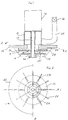
- the device according to this invention is of the type which includes a drive motor 16 mounted on a wind box 18 in which opens the end of a gas intake manifold 20.
- This engine drives a set of turbines via its rotation shaft 14.
- This assembly comprises a radial diffusion turbine 12 coupled to a turbine mixing 10.
- the set of 10-12 turbines is held by keying at the end of the shaft 14 in a hub 32.
- the gas for example pressurized air or not, is brought to the center of the turbine diffusion 12 between the fins of the latter as indicated by the arrows on Figure 1.
- the set of turbines thus described is immersed within the mass liquid to be aerated and stirred.
- each radial fin such as 24 or 26 and each blade of the stirring turbine 10 have a common edge. Thanks to this characteristic, we promote relaxation pressurized liquid and therefore the diffusion of micro-bubbles within the liquid mass. The latter is therefore more homogeneous because it is caught in the flow rising which is generated by the blades of the stirring turbine 10 which are extended by the fins 24, 26 of the radial diffusion turbine 12.
- the height of the blades of the stirring turbine 10 is chosen as a function of desired intensity of brewing.
- the set of turbines is mounted under a hydraulic plate 22 on which are fixed the wind box 18, the motor 16 and the gas intake pipe 20.
- fins discharge such as 28 (FIGS. 1 and 2) which are mounted above the plate 36 on which are mounted, under its underside, the two types of radial fins 24, 26 of the diffusion turbine 12.
- a valve in particular a ball valve 30, placed on the gas intake pipe 20 in order to allow adjustment of the volume of air admitted into the device, allowing thus an empirical adjustment of the air / solid ratio, i.e. the weight of air released (in kilos) per kilogram of suspended matter.
- the supply of gas for example air or oxygen can be performed via a compressor supplying the intake manifold gas 20, in case large flows are required. Note that this feature brings great flexibility as it allows to use simultaneously the compressor and the turbines during peak periods and turbines only outside such periods.
- the device object of the invention makes it possible to simultaneously carry out oxygenation by diffusion of bubbles very fine air or oxygen through a liquid mass and mixing homogeneous of this mass.
- the device according to the invention can be applied to degreasing and deoiling waste effluents. It is then immersed in the liquid mass so that the air released into this mass, in the form of very fine bubbles dispersed within liquid mass, promotes the flotation of fat and foam on the surface ; the device then has the advantage of also allowing mixing of the bottom without agitation of the surface likely to disturb the film or the layer of flotation materials.
- the device according to the invention can also be used in a biological water treatment plant using activated sludge. He is immersed in the liquid mass and supplied preferably with compressed air (or oxygen). II then simultaneously ensures oxygenation of the effluent allowing the aerobic bacteria to live and multiply, thanks to the formation of fine bubbles air (or oxygen) within the liquid mass and a mixing of this same liquid mass to keep the activated sludge in suspension and to ensure the homogeneity of the mixture.
- compressed air or oxygen
Claims (7)
- Vorrichtung zum Einleiten eines Gases in eine Flüssigkeit, welche einen Antriebsmotor (16), ein Gasgehäuse (18), ein Gaseinlassrohr (20), einen Mischungsrührer (10) und einen radialen Diffusionsrührer (12), der an den Mischungsrührer gekoppelt ist, umfasst, wobei die beiden Rührer in die flüssige Masse eintauchen und das Gas in die Mitte des Diffusionsrührers gebracht und zwischen dessen Flügeln verteilt wird, dadurch gekennzeichnet, dass der Diffusionsrührer (12) eine Vielzahl radialer Flügel (24) mit großer Länge enthält, die bis zur Welle (14) des Mischungsrührers reichen und sich mit radialen Flügeln (26) mit kürzerer Länge abwechseln, die nicht bis zur Welle (14) reichen, um einen freien Zwischenraum zwischen dieser Welle und den jeweiligen Innenkanten (26') der radialen Flügel (26) zu lassen, wobei die beiden Sätze von Flügeln (24, 26) unter einer Platte (36) befestigt sind, die von der Welle in Umdrehung versetzt wird, und dass die radialen Flügel (24, 26) des Diffusionsrührers (12) die Schaufelblätter des Mischungsrührers (10) bis in eine Zone mit relativem Unterdruck seitlich verlängern, die sich hinter dem Rührer befindet, und Entnahmeflügel (28) vorgesehen werden, die über der Platte (36) angebracht sind, die an ihrer Unterseite die Flügel (24, 26) des radialen Diffusionsrührers (12) aufnimmt.
- Vorrichtung nach Anspruch 1, dadurch gekennzeichnet, dass die beiden Rührer (10, 12) unter einer Hydraulikplattform (22) angebracht sind, auf welcher der Antriebsmotor (16), das Gasgehäuse (18) und das Gaseinlassrohr (20) befestigt sind.
- Vorrichtung nach einem der vorhergehenden Ansprüche, dadurch gekennzeichnet, dass ein im Gaseinlassrohr (20) angeordnetes Ventil (30), insbesondere ein Kegelventil, vorgesehen ist, um den eingeleiteten Gasdurchfluss in den Rührer zu regeln.
- Vorrichtung nach einem der vorhergehenden Ansprüche, dadurch gekennzeichnet, dass die Höhe der Schaufelblätter des Mischungsrührers (10) in Abhängigkeit von der gewünschten Stärke der Durchmischung festgelegt wird.
- Vorrichtung nach einem der vorhergehenden Ansprüche, dadurch gekennzeichnet, dass die Gaszuleitung über einen Verdichter erfolgt, der in das Gaseinlassrohr (20) abgibt.
- Verwendung der Vorrichtung nach einem der vorhergehenden Ansprüche zum Abscheiden von Fett und Öl aus Abflüssen, wobei die Vorrichtung in die flüssige Masse derart eintaucht, dass die in Form von in der flüssigen Masse dispergierten sehr feinen Bläschen in diese Masse freigesetzte Luft die Ansammlung von Fett und Schaum an der Oberfläche begünstigt.
- Verwendung der Vorrichtung nach einem der Ansprüche 1 bis 6 zur biologischen Behandlung von Wasser durch Belebtschlamm, wobei die Vorrichtung in die flüssige Masse eintaucht und vorzugsweise Druckluft derart einleitet, dass gleichzeitig für eine Oxidation des Abflusses durch Durchperlen von Luftbläschen durch die flüssige Masse und eine Durchmischung dieser flüssigen Masse gesorgt wird, damit der Belebtschlamm suspendiert und die Homogenität des Gemischs sichergestellt bleibt.
Applications Claiming Priority (2)
| Application Number | Priority Date | Filing Date | Title |
|---|---|---|---|
| FR9503892 | 1995-04-03 | ||
| FR9503892A FR2732236B1 (fr) | 1995-04-03 | 1995-04-03 | Dispositif pour introduire un gaz dans un liquide |
Publications (2)
| Publication Number | Publication Date |
|---|---|
| EP0736322A1 EP0736322A1 (de) | 1996-10-09 |
| EP0736322B1 true EP0736322B1 (de) | 2001-07-18 |
Family
ID=9477677
Family Applications (1)
| Application Number | Title | Priority Date | Filing Date |
|---|---|---|---|
| EP19960400583 Expired - Lifetime EP0736322B1 (de) | 1995-04-03 | 1996-03-20 | Vorrichtung zum Einbringen eines Gases in eine Flüssigkeit |
Country Status (8)
| Country | Link |
|---|---|
| US (1) | US5643503A (de) |
| EP (1) | EP0736322B1 (de) |
| AT (1) | ATE203183T1 (de) |
| DE (1) | DE69613881T2 (de) |
| DK (1) | DK0736322T3 (de) |
| ES (1) | ES2160215T3 (de) |
| FR (1) | FR2732236B1 (de) |
| PT (1) | PT736322E (de) |
Families Citing this family (10)
| Publication number | Priority date | Publication date | Assignee | Title |
|---|---|---|---|---|
| US5988600A (en) * | 1997-11-19 | 1999-11-23 | Keepalive, Inc. | Multi-stage aerator |
| US6394423B1 (en) * | 1997-11-19 | 2002-05-28 | Thomas Joseph Vento | Multi-stage aerator |
| FR2820653B1 (fr) * | 2001-02-14 | 2004-05-28 | Georges Ponthieu | Dispositif de diffusion d'un gaz dans un liquide par une turbine a ailettes |
| FR2848472B1 (fr) * | 2002-12-12 | 2005-02-18 | Air Liquide | Dispositif d'agitation d'un liquide et d'injection d'un gaz dans ce liquide a engorgement limite |
| FR2859645A1 (fr) * | 2003-09-17 | 2005-03-18 | Air Liquide | Procede d'amelioration de la capacite d'injection d'un gaz dans un liquide produite par un dispositif d'agitation et d'injection |
| ITVE20040015A1 (it) * | 2004-04-22 | 2004-07-22 | Hydor Srl | Aeratore rotante per acquari |
| WO2009055415A2 (en) * | 2007-10-24 | 2009-04-30 | Hmicro, Inc. | A flexible wireless patch for physiological monitoring and methods of manufacturing the same |
| US20110101547A1 (en) * | 2007-10-18 | 2011-05-05 | Cach Van Nguyen | Fluidization aeration mixing apparatus |
| CA2919280A1 (en) | 2016-01-29 | 2017-07-29 | Richard Ladouceur | Rotary gas bubble ejector |
| CN112723454B (zh) * | 2020-12-04 | 2022-09-06 | 成都市蜀科科技有限责任公司 | 一种污水处理用高效射流气浮机 |
Family Cites Families (16)
| Publication number | Priority date | Publication date | Assignee | Title |
|---|---|---|---|---|
| US2348990A (en) * | 1940-07-01 | 1944-05-16 | Stearns Roger Mfg Company | Aerating apparatus |
| US2343274A (en) * | 1940-10-29 | 1944-03-07 | Mining Process & Patent Co | Flotation machine |
| DE828100C (de) * | 1948-10-02 | 1952-01-14 | Werner Herold | In beiden Achsrichtungen saugender Mischkreisel |
| US2743914A (en) * | 1950-09-27 | 1956-05-01 | American Instr Co Inc | Gas-liquid mixing apparatus |
| US2767965A (en) * | 1950-11-03 | 1956-10-23 | Mining Process & Patent Co | Dual pumping agitation |
| US2944802A (en) * | 1955-02-16 | 1960-07-12 | Denver Equip Co | Froth flotation and aeration apparatus |
| US3490996A (en) * | 1968-04-10 | 1970-01-20 | Herbert C Kelly Jr | Solar heated water vapor lifting and condensing system |
| US3984001A (en) * | 1974-03-25 | 1976-10-05 | Mitsui Mining & Smelting Co., Ltd. | Bubble-dispersing apparatus |
| FR2293235A1 (fr) * | 1974-12-05 | 1976-07-02 | Roland Jean Louis | Dispositif pour introduire un gaz dans un liquide |
| DE2544204A1 (de) * | 1975-10-03 | 1977-04-14 | Bayer Ag | Vorrichtung zum begasen und ruehren von suspensionen und fluessigkeiten |
| DE2559234A1 (de) * | 1975-12-30 | 1977-07-14 | Poepel Franz Prof Dr Ing Habil | Einrichtung zur begasung von fluessigkeit |
| DE2559236A1 (de) * | 1975-12-30 | 1977-07-14 | Poepel Franz Prof Dr Ing Habil | Einrichtung zur begasung von fluessigkeit |
| DE2823801A1 (de) * | 1977-06-23 | 1979-01-18 | Makoto Naito | Vorrichtung zum verteilen von gas in form von feinen gasblaeschen in einer fluessigkeit |
| JPS5643398Y2 (de) * | 1977-06-23 | 1981-10-12 | ||
| US5160459A (en) * | 1990-11-27 | 1992-11-03 | Claudio Guarnaschelli | Fluid mixer |
| CH686874A5 (de) * | 1992-01-31 | 1996-07-31 | V Zug Ag | Vorrichtung zum Einbringen eines Gases in eine Fluessigkeit. |
-
1995
- 1995-04-03 FR FR9503892A patent/FR2732236B1/fr not_active Expired - Fee Related
-
1996
- 1996-03-20 AT AT96400583T patent/ATE203183T1/de not_active IP Right Cessation
- 1996-03-20 EP EP19960400583 patent/EP0736322B1/de not_active Expired - Lifetime
- 1996-03-20 DK DK96400583T patent/DK0736322T3/da active
- 1996-03-20 ES ES96400583T patent/ES2160215T3/es not_active Expired - Lifetime
- 1996-03-20 PT PT96400583T patent/PT736322E/pt unknown
- 1996-03-20 DE DE1996613881 patent/DE69613881T2/de not_active Expired - Fee Related
- 1996-03-22 US US08/620,378 patent/US5643503A/en not_active Expired - Lifetime
Also Published As
| Publication number | Publication date |
|---|---|
| ES2160215T3 (es) | 2001-11-01 |
| ATE203183T1 (de) | 2001-08-15 |
| DE69613881T2 (de) | 2002-04-04 |
| EP0736322A1 (de) | 1996-10-09 |
| DE69613881D1 (de) | 2001-08-23 |
| PT736322E (pt) | 2002-01-30 |
| DK0736322T3 (da) | 2001-10-29 |
| FR2732236B1 (fr) | 1997-06-06 |
| US5643503A (en) | 1997-07-01 |
| FR2732236A1 (fr) | 1996-10-04 |
Similar Documents
| Publication | Publication Date | Title |
|---|---|---|
| EP1697053B1 (de) | Verfahren und reaktor zur flockungsbehandlung. | |
| EP0736322B1 (de) | Vorrichtung zum Einbringen eines Gases in eine Flüssigkeit | |
| EP0954373B1 (de) | Vorrichtung zum rühren und belüften einer flüssigkeit sowie zur schaumentfernung in einem flüssigkeitsbehandlungsbottich | |
| US20050173336A1 (en) | Methods and apparatus for enhancing venturi suction in eductor mixers | |
| EP0996497A1 (de) | Gerät und verfahren zur behandlung von flüssigkeiten | |
| JPH084795B2 (ja) | 高水没性回転型微生物接触装置 | |
| EP2714256B1 (de) | Vorrichtung zur einspritzung eines gases in eine senkgrube | |
| US6572774B2 (en) | Waste treatment method and apparatus with integral clarifier | |
| EP1156870B1 (de) | Vorrichtung und verfahren zur behandlung von verunreinigten medien | |
| EP3026022A1 (de) | Mikro-station zur biologischen reinigung | |
| JP2006320777A (ja) | 排水処理装置 | |
| US20060087047A1 (en) | Fluid mixing apparatus | |
| EP2188215B1 (de) | Verfahren zur flüssigkeits-/feststofftrennung in abwässern sowie dazugehörige trennvorrichtung | |
| EP2247538B1 (de) | Vorrichtung zur reinigung städtischer abwässer durch aktivierten schlamm in einem geschlossenen reaktor | |
| CN2727456Y (zh) | 一种曝气机风叶轮 | |
| FR2839898A1 (fr) | Dispositif d'aeration et de brassage d'eaux usees dans un reacteur de traitement, son utilisation pour l'epuration des eaux usees et son utilisation en tant que fermenteur | |
| JP2000117081A (ja) | 水中攪拌装置 | |
| RU2114793C1 (ru) | Установка биологической очистки сточных вод | |
| CH368433A (fr) | Installation de traitement des eaux usées | |
| JPH03114583A (ja) | 分散空気浮揚装置及びその方法 | |
| EP1232784A1 (de) | Vorrichtung zur Diffusion von einem Gas in einer Flüssigkeit mittels einer Schaufelturbine | |
| FR2749840A1 (fr) | Station d'epuration des eaux usees | |
| FR2840237A1 (fr) | Bac de dissolution melangeur multi usages | |
| EP2536667A1 (de) | Anlage zur behandlung von gärresten aus mindestens einer kammer zur methanierung von weitgehend organischen materialien | |
| CH612594A5 (en) | Device for mixing gas and liquid and use of the device |
Legal Events
| Date | Code | Title | Description |
|---|---|---|---|
| PUAI | Public reference made under article 153(3) epc to a published international application that has entered the european phase |
Free format text: ORIGINAL CODE: 0009012 |
|
| AK | Designated contracting states |
Kind code of ref document: A1 Designated state(s): AT BE CH DE DK ES FR GB IE IT LI NL PT SE |
|
| 17P | Request for examination filed |
Effective date: 19970228 |
|
| 17Q | First examination report despatched |
Effective date: 20000114 |
|
| GRAG | Despatch of communication of intention to grant |
Free format text: ORIGINAL CODE: EPIDOS AGRA |
|
| GRAG | Despatch of communication of intention to grant |
Free format text: ORIGINAL CODE: EPIDOS AGRA |
|
| GRAG | Despatch of communication of intention to grant |
Free format text: ORIGINAL CODE: EPIDOS AGRA |
|
| GRAH | Despatch of communication of intention to grant a patent |
Free format text: ORIGINAL CODE: EPIDOS IGRA |
|
| GRAG | Despatch of communication of intention to grant |
Free format text: ORIGINAL CODE: EPIDOS AGRA |
|
| GRAG | Despatch of communication of intention to grant |
Free format text: ORIGINAL CODE: EPIDOS AGRA |
|
| GRAH | Despatch of communication of intention to grant a patent |
Free format text: ORIGINAL CODE: EPIDOS IGRA |
|
| GRAH | Despatch of communication of intention to grant a patent |
Free format text: ORIGINAL CODE: EPIDOS IGRA |
|
| GRAA | (expected) grant |
Free format text: ORIGINAL CODE: 0009210 |
|
| RAP1 | Party data changed (applicant data changed or rights of an application transferred) |
Owner name: EURODEPOL |
|
| RIN1 | Information on inventor provided before grant (corrected) |
Inventor name: ROLAND, JEAN-LOUIS GASTON FELIX |
|
| ITF | It: translation for a ep patent filed |
Owner name: BARZANO' E ZANARDO MILANO S.P.A. |
|
| AK | Designated contracting states |
Kind code of ref document: B1 Designated state(s): AT BE CH DE DK ES FR GB IE IT LI NL PT SE |
|
| REF | Corresponds to: |
Ref document number: 203183 Country of ref document: AT Date of ref document: 20010815 Kind code of ref document: T |
|
| REG | Reference to a national code |
Ref country code: CH Ref legal event code: EP |
|
| REG | Reference to a national code |
Ref country code: IE Ref legal event code: FG4D Free format text: FRENCH |
|
| REF | Corresponds to: |
Ref document number: 69613881 Country of ref document: DE Date of ref document: 20010823 |
|
| GBT | Gb: translation of ep patent filed (gb section 77(6)(a)/1977) |
Effective date: 20010808 |
|
| REG | Reference to a national code |
Ref country code: DK Ref legal event code: T3 |
|
| REG | Reference to a national code |
Ref country code: ES Ref legal event code: FG2A Ref document number: 2160215 Country of ref document: ES Kind code of ref document: T3 |
|
| REG | Reference to a national code |
Ref country code: GB Ref legal event code: IF02 |
|
| REG | Reference to a national code |
Ref country code: PT Ref legal event code: SC4A Free format text: AVAILABILITY OF NATIONAL TRANSLATION Effective date: 20011012 |
|
| PLBE | No opposition filed within time limit |
Free format text: ORIGINAL CODE: 0009261 |
|
| STAA | Information on the status of an ep patent application or granted ep patent |
Free format text: STATUS: NO OPPOSITION FILED WITHIN TIME LIMIT |
|
| 26N | No opposition filed | ||
| PGFP | Annual fee paid to national office [announced via postgrant information from national office to epo] |
Ref country code: IE Payment date: 20030321 Year of fee payment: 8 |
|
| PGFP | Annual fee paid to national office [announced via postgrant information from national office to epo] |
Ref country code: DK Payment date: 20030327 Year of fee payment: 8 |
|
| PGFP | Annual fee paid to national office [announced via postgrant information from national office to epo] |
Ref country code: AT Payment date: 20030331 Year of fee payment: 8 |
|
| PG25 | Lapsed in a contracting state [announced via postgrant information from national office to epo] |
Ref country code: AT Free format text: LAPSE BECAUSE OF NON-PAYMENT OF DUE FEES Effective date: 20040320 |
|
| PG25 | Lapsed in a contracting state [announced via postgrant information from national office to epo] |
Ref country code: SE Free format text: LAPSE BECAUSE OF NON-PAYMENT OF DUE FEES Effective date: 20040321 |
|
| PG25 | Lapsed in a contracting state [announced via postgrant information from national office to epo] |
Ref country code: IE Free format text: LAPSE BECAUSE OF NON-PAYMENT OF DUE FEES Effective date: 20040322 |
|
| PG25 | Lapsed in a contracting state [announced via postgrant information from national office to epo] |
Ref country code: DK Free format text: LAPSE BECAUSE OF NON-PAYMENT OF DUE FEES Effective date: 20040331 |
|
| EUG | Se: european patent has lapsed | ||
| REG | Reference to a national code |
Ref country code: PT Ref legal event code: MM4A Free format text: LAPSE DUE TO NON-PAYMENT OF FEES Effective date: 20040930 |
|
| REG | Reference to a national code |
Ref country code: IE Ref legal event code: MM4A |
|
| PGFP | Annual fee paid to national office [announced via postgrant information from national office to epo] |
Ref country code: SE Payment date: 20050331 Year of fee payment: 10 |
|
| REG | Reference to a national code |
Ref country code: CH Ref legal event code: PUE Owner name: CITEE Free format text: EURODEPOL#40 BIS RUE J.J. ROUSSEAU#92700 COLOMBES (FR) -TRANSFER TO- CITEE#ESPACE DUO 453 CH. DE LA FARLEDE ZAC LES PLAYES JEAN MONNET NORD#83500 LA-SEYNE-SUR-MER (FR) Ref country code: CH Ref legal event code: PFA Owner name: CITEE Free format text: CITEE#ESPACE DUO 453 CH. DE LA FARLEDE ZAC LES PLAYES JEAN MONNET NORD#83500 LA-SEYNE-SUR-MER (FR) -TRANSFER TO- CITEE#8, RUE JACQUES LEMERCIER#78000 VERSAILLES (FR) Ref country code: PT Ref legal event code: NF4A Free format text: RESTITUTIO IN INTEGRUM Effective date: 20050404 |
|
| REG | Reference to a national code |
Ref country code: FR Ref legal event code: TP |
|
| BECA | Be: change of holder's address |
Owner name: *CITEE8, RUE JACQUES LEMERCIER, F-78000 VERSAILLES Effective date: 20050628 |
|
| NLS | Nl: assignments of ep-patents |
Owner name: CITEE S.R.L. |
|
| REG | Reference to a national code |
Ref country code: GB Ref legal event code: 732E |
|
| REG | Reference to a national code |
Ref country code: FR Ref legal event code: CJ Ref country code: FR Ref legal event code: CA |
|
| REG | Reference to a national code |
Ref country code: ES Ref legal event code: PC2A |
|
| BECA | Be: change of holder's address |
Owner name: *CITEE8, RUE JACQUES LEMERCIER, F-78000 VERSAILLES Effective date: 20050628 |
|
| PGFP | Annual fee paid to national office [announced via postgrant information from national office to epo] |
Ref country code: NL Payment date: 20090317 Year of fee payment: 14 |
|
| PGFP | Annual fee paid to national office [announced via postgrant information from national office to epo] |
Ref country code: GB Payment date: 20090325 Year of fee payment: 14 Ref country code: CH Payment date: 20090316 Year of fee payment: 14 |
|
| PGFP | Annual fee paid to national office [announced via postgrant information from national office to epo] |
Ref country code: DE Payment date: 20090320 Year of fee payment: 14 |
|
| PGFP | Annual fee paid to national office [announced via postgrant information from national office to epo] |
Ref country code: BE Payment date: 20090430 Year of fee payment: 14 |
|
| BERE | Be: lapsed |
Owner name: *CITEE Effective date: 20100331 |
|
| REG | Reference to a national code |
Ref country code: NL Ref legal event code: V1 Effective date: 20101001 |
|
| REG | Reference to a national code |
Ref country code: CH Ref legal event code: PL |
|
| GBPC | Gb: european patent ceased through non-payment of renewal fee |
Effective date: 20100320 |
|
| PG25 | Lapsed in a contracting state [announced via postgrant information from national office to epo] |
Ref country code: NL Free format text: LAPSE BECAUSE OF NON-PAYMENT OF DUE FEES Effective date: 20101001 |
|
| PG25 | Lapsed in a contracting state [announced via postgrant information from national office to epo] |
Ref country code: LI Free format text: LAPSE BECAUSE OF NON-PAYMENT OF DUE FEES Effective date: 20100331 Ref country code: DE Free format text: LAPSE BECAUSE OF NON-PAYMENT OF DUE FEES Effective date: 20101001 Ref country code: CH Free format text: LAPSE BECAUSE OF NON-PAYMENT OF DUE FEES Effective date: 20100331 Ref country code: BE Free format text: LAPSE BECAUSE OF NON-PAYMENT OF DUE FEES Effective date: 20100331 |
|
| PG25 | Lapsed in a contracting state [announced via postgrant information from national office to epo] |
Ref country code: GB Free format text: LAPSE BECAUSE OF NON-PAYMENT OF DUE FEES Effective date: 20100320 |
|
| PGFP | Annual fee paid to national office [announced via postgrant information from national office to epo] |
Ref country code: IT Payment date: 20120310 Year of fee payment: 17 |
|
| REG | Reference to a national code |
Ref country code: FR Ref legal event code: PLFP Year of fee payment: 20 |
|
| PG25 | Lapsed in a contracting state [announced via postgrant information from national office to epo] |
Ref country code: IT Free format text: LAPSE BECAUSE OF NON-PAYMENT OF DUE FEES Effective date: 20140320 |
|
| PGFP | Annual fee paid to national office [announced via postgrant information from national office to epo] |
Ref country code: ES Payment date: 20150225 Year of fee payment: 20 Ref country code: PT Payment date: 20150306 Year of fee payment: 20 |
|
| PGFP | Annual fee paid to national office [announced via postgrant information from national office to epo] |
Ref country code: FR Payment date: 20150224 Year of fee payment: 20 |
|
| REG | Reference to a national code |
Ref country code: PT Ref legal event code: MM4A Free format text: MAXIMUM VALIDITY LIMIT REACHED Effective date: 20160320 |
|
| PG25 | Lapsed in a contracting state [announced via postgrant information from national office to epo] |
Ref country code: PT Free format text: LAPSE BECAUSE OF EXPIRATION OF PROTECTION Effective date: 20160329 |
|
| REG | Reference to a national code |
Ref country code: ES Ref legal event code: FD2A Effective date: 20160627 |
|
| PG25 | Lapsed in a contracting state [announced via postgrant information from national office to epo] |
Ref country code: ES Free format text: LAPSE BECAUSE OF EXPIRATION OF PROTECTION Effective date: 20160321 |