EP0736270A1 - Method and device for processing brushes - Google Patents
Method and device for processing brushes Download PDFInfo
- Publication number
- EP0736270A1 EP0736270A1 EP96200542A EP96200542A EP0736270A1 EP 0736270 A1 EP0736270 A1 EP 0736270A1 EP 96200542 A EP96200542 A EP 96200542A EP 96200542 A EP96200542 A EP 96200542A EP 0736270 A1 EP0736270 A1 EP 0736270A1
- Authority
- EP
- European Patent Office
- Prior art keywords
- brush
- fibres
- displacement
- brush fibres
- elements
- Prior art date
- Legal status (The legal status is an assumption and is not a legal conclusion. Google has not performed a legal analysis and makes no representation as to the accuracy of the status listed.)
- Granted
Links
Images


Classifications
-
- A—HUMAN NECESSITIES
- A46—BRUSHWARE
- A46D—MANUFACTURE OF BRUSHES
- A46D9/00—Machines for finishing brushes
- A46D9/02—Cutting; Trimming
- A46D9/025—Deflecting parts of the bristle field in order to trim the rest
-
- A—HUMAN NECESSITIES
- A46—BRUSHWARE
- A46B—BRUSHES
- A46B9/00—Arrangements of the bristles in the brush body
- A46B9/02—Position or arrangement of bristles in relation to surface of the brush body, e.g. inclined, in rows, in groups
- A46B9/028—Bristle profile, the end of the bristle defining a surface other than a single plane or deviating from a simple geometric form, e.g. cylinder, sphere or cone
-
- A—HUMAN NECESSITIES
- A46—BRUSHWARE
- A46D—MANUFACTURE OF BRUSHES
- A46D9/00—Machines for finishing brushes
- A46D9/02—Cutting; Trimming
Definitions
- the present invention concerns a method and device for processing brushes, in particular for brushes whereby the brush fibres need to be separated and processed in different fields, for example need to be cut and/or warped and/or rounded off at different levels in one and the same machine.
- the invention is meant for tooth brushes, but in general it can also be used for other brushes.
- brushes have been invented whose fibres have more than two different levels.
- these levels can be simulated certain profiles in the brush field. These profiles can be provided both crosswise and in the longitudinal direction of the brush. These profiles can among others also be convex or concave.
- the invention aims a method and device which make it possible to warp and round off brush fibres of different lengths in an advantageous manner, irrespective of the shape of the profile in the brush field.
- the starting point hereby is for example that fibres with clearly different lengths are first inserted, such that fields of different height levels are created. At each level, however, there are small tolerance differences as far as the height of the brush fibres is concerned, which are eliminated in the known manner by warping the fibre ends even, which is usually followed by a rounding off or milling operation to remove the sharp edges of the crosscut ends of the brush fibres.
- the invention in this case aims a particularly advantageous solution to separate the brush fibres of the obtained raw brush in clearly distinct fields, so that the fibres of a field form no hindrance to carry out the warping and rounding off operations to the fibres of another field.
- the invention also aims a method and device which makes it possible to divide the brush fibres of a brush in fields, even when they have equal or almost equal lengths. After the division, the brush fibres of the thus clearly defined fields can be subjected to different treatments. It is even possible then to make a brush with different levels out of a brush which is originally provided with fibres of the same length, for example by shortening the fibres of certain fields, by cutting them or by warping them somewhat deeper.
- the invention in the first place concerns a method for processing brushes, whereby the brush fibres of these brushes are divided in clearly separated fields and are subsequently treated separately per field, characterized in that the brush fibres are divided in separate fields by subsequently displacing a number of the brush fibres by bending them by means of one or more displacement elements, by retaining at least part of the displaced brush fibres in bent condition by means of one or more auxiliary elements, and by redrawing the displacement elements.
- the displacement elements are put in contact with the fibres by shifting them sideways, either or not followed by a movement towards the brush body.
- the displacement elements will be moved until only the brush fibres to be retained by the auxiliary elements protrude under the displacement elements with slantingly bent ends, so that the auxiliary elements can be positioned against these protruding ends.
- the auxiliary elements after the above-mentioned movement of the displacement elements, are preferably presented above the above-mentioned ends in relation to the brush and they are possibly also moved towards the brush body.
- displacement elements and auxiliary elements which are adjusted to the shape of the fields to be separated.
- the displacement, the retaining and the treatment are preferably carried out systematically, whereby all brush fibres, to the exception of the shortest, are first displaced and retained, while the shortest are treated, after which these steps are each time successively repeated, whereby the brush fibres of each time a somewhat longer length are step by step released for treatment.
- the method is characterized in that the brushes are moved in a transport device, whereby the fibres to be treated each time are at least presented to a warp station and a rounding off station; in that the brush fibres are displaced by means of displacement elements which are erected next to the transport device; in that the brush fibres are retained by means of auxiliary elements which move with the transport device; and in that the brush fibres are permanently retained by the auxiliary elements each time after the displacement until they have been presented both to the warp station and the rounding off station.
- the invention also concerns a device, in particular a device which is provided with means to divide the brush fibres of a brush in different fields, so as to be able to treat the brush fibres separately per field, characterized in that the above-mentioned means consist of the combination of at least one displacement element to bend brush fibres and at least one auxiliary element to hold at least a part of the brush fibres bent by the displacement element in the bent shape.
- the invention is related to the processing of brushes 1 which have brush fibres 2 of various lengths.
- the brush fibres 2 of the outermost rows of fibre bundles 3 are longer than the brush fibres 2 of the middle field 4.
- these means consist of the combination of displacement elements 5A-5B to bend the brush fibres 2 and auxiliary means 6A-6B to hold at least part of the brush fibres 2 bent by the displacement elements 5A-5B in the bent shape.
- the displacement elements 5A-5B consist of plates which can be moved sideways which can be pressed sideways with their crosscut ends 7 against the brush fibres 2, such at a required height in relation to the brush body 8 of the brush 1.
- the auxiliary means 6A-6B also consist of plates which are situated and/or can be situated on either side of a brush 1 provided in the device 9, and which can be moved sideways towards one another, and which thus can also be put in contact with the brush fibres 2 with their ends 10.
- the auxiliary elements 6A-6B are situated immediately under the displacement elements 5A-5B.
- the shapes of the ends 7 and 10 are preferably adjusted to the shape of the fibre fields of the brush 1 concerned, as is clearly visible in figure 1.
- step by step in figures 2 to 10 is represented step by step in figures 2 to 10 and is mainly as follows.
- Figure 2 shows the initial position, whereby the displacement elements 5A-5B and the auxiliary elements 6A-6B are situated next to the brush 1, at the height of the brush fibres 2, for example at a certain height A.
- fibres which already have different lengths after the filling which implies that the filling machine has used fibres of different lengths.
- the fibres can all have the same length before the displacement is started.
- the fibres can either stay unwarped before the displacement starts, or they can be warped before the displacement starts, so that all fibre ends lie in one single field.
- the latter can be particularly interesting when fibre fields must be warped and/or rounded off at different lengths and when these fibre fields do not consist of individual fibre bundles, but when the fibre fields extend over parts of fibre bundles, for example 1/2 or 3/4 of certain fibre bundles; this implies that a part of the brush fibres of a fibre bundle belongs to the first level, whereas the remaining brush fibres of the same bundle belong to one or several different levels.
- the displacement element 5A is pulled out, whereby at least the longer brush fibres 2 are pushed away.
- This displacement element 5A is hereby moved until a position is reached in which only the longer brush fibres 2, with slantingly bent ends 11, extend from under said displacement element 5A, as is represented in figure 3.
- the displacement element 5A can possibly be shifted somewhat towards the brush body 8, for example at a distance B, as is represented in figure 4.
- Figure 5 shows how the auxiliary element 6A is positioned above the free ends 11, after which, as in figure 6, the displacement element 5A can be pulled back.
- the auxiliary element 6A can hereby be moved downward at a distance B from the brush body 8.
- the invention is mainly designed to carry out treatments, such as warping and rounding off the brush fibre ends 11, by means of a warp station 13 and a rounding off station 14 known as such.
- the invention can also be used in combination with other final processings.
- the displacement elements 5A-5B and the auxiliary elements 6A-6B are of course equipped with the necessary drive means. It is clear that they can be of different nature. By way of example, two embodiments thereof are represented schematically in figures 11 and 12, in particular of the drive means 15 to move the auxiliary elements 6A-6B.
- auxiliary elements 6A-6B which are made in the shape of carriages which can be moved by means of drive elements 16.
- Figure 13 shows a variant in which a displacement element 5C is used which mainly consists of a standing wall 19 which extends in relation to the insertion field 18 of the brush 1 to be treated.
- the shape of the wall 19 is preferably adjusted to the design of the brush fields of the brush 1.
- the displacement element 5C, and in particular the wall 19 is also made in the shape of a ring as represented in figure 13, one and other such that two opposite edges 20A and 20B are formed to displace the brush fibres 2, whereby these edges have the same function as the above-mentioned crosscut edges 7 of the displacement elements 5A and 5B represented in figure 1.
- FIG. 14 The working of the device 9 of figure 13 is schematically illustrated in figures 14 to 17.
- the displacement element 5C is moved sideways by the brush fibres 2 until the above-mentioned ends 11 of a number of the longest brush fibres 2 are bent sideways, such that they can be picked up and held by the auxiliary element 6B as represented in the figures 15 and 16 and analogous to the figures 8 and 9.
- a displacement element 5C which consists of a standing wall 19, and preferably in the shape of a ring, is advantageous in that once the wall has moved through a brush field, the brush fibres 2 concerned immediately spring back after said wall has passed, thanks to the limited thickness of the wall 19, and thus do not remain pushed back all the time, which in certain cases, depending on the type of brush fibres 2, could lead to permanent distortions.
- Figure 18 shows how all brush fibres 2, to the exception of the shortest, can be displaced by means of a displacement element 5C. Since the displacement itself is carried out in a similar manner as is represented in figures 14 to 17, not all steps are represented here.
- auxiliary elements 6A and 6B can stand in any position whatsoever at the same distance Y from one another, so that a setting with two positions may suffice for the drive thereof, an open position as represented in figure 18 and a somewhat more closed position as represented in figures 19 to 21 respectively.
- auxiliary elements 6A-6B can be adjusted in said and the preceding embodiments between more than two positions.
- the device 9 according to the invention is particularly suitable for pushing away rows of fibres or groups of fibres which can have any contour or shape whatsoever.
- a variant of the embodiment of figure 13 is represented by way of example in figure 23, which is meant to be used with brushes 1 with a circular brush field.
- Such brushes 1 are used for example as a rotating brush head in an electric tooth brush.
- the wall 19 is hereby circular and the crosscut ends 10 are semi-circular.
- Figures 24 to 27 show a variant which is particularly suitable for brushes 1 with a circular fibre field, but which, with an adjusted design, could also be used for brushes 1 with brush fields in other shapes.
- a displacement element 5D which is mainly formed of an elastic part which can be spread sideways by means of a plunger 21 which can be moved in this elastic part.
- the displacement element 5D is hereby held in a head 22 which makes it possible to bring the displacement element 5D along the free ends of the brush fibres 2 between these brush fibres 2, by means of a mutual shift between this head 22 and the brush 1.
- the displacement element 5D preferably has a profiled edge 23 which partly causes the spreading of the brush fibres 2 that touch it.
- a first step the head 22 and the brush 1 are presented on top of one another, as shown in figure 22.
- a next step which is represented in figure 25, the head 22 and the brush 1 are moved mutually towards one another, for example due to the shift of the head 22, until the bottommost end 24 is situated above the shortest brush fibres 2, but between the longest brush fibres 2.
- the displacement element 5D is spread elastically and the longest brush fibres 2 are also pressed out by the edge 23, as is represented ni figure 26.
- the longest brush fibres 2 are bent further outward, as they are bent around against the profiled edge 23.
- the brush fibres 2 can be retained by means of auxiliary elements 6A-6B, the head 22 with the displacement element 5D can be removed again and the final processing of the shortest brush fibres, such as warping and rounding off, can be carried out.
- the brushes 1 are preferably moved in a transport device, whereby the fibres to be processed are each time successively presented to a warp station and a rounding off station, and preferably, the brush fibres 2 are displaced by means of displacement elements, for example 5A and 5B, which are erected next to the transport device on the one hand, and the brush fibres 2 are retained by means of auxiliary elements 6A-6B which move along with the transport device on the other hand.
- displacement elements for example 5A and 5B
- auxiliary elements 6A-6B which move along with the transport device on the other hand.
- figures 28, 29 and 30 show an embodiment in which the auxiliary means 6A and 6B as well as the drive means 15 thereof are mounted on such a transport device 25, which for example consists of an endless chain, and are controlled by means of a cam drive.
- the brush 1 is hereby clamped in a clamp 26 mounted on the transport device 25, with clamping shoes 27-28-29 as is known among others from EP. 0.078.569.
- the auxiliary elements 6A-6B are mounted in a rotating manner on the transport device 25, whereby they can rotate around pivots 31A-31B by means of rolling arms 30A-30B.
- the drive means 15 to activate the auxiliary elements 6A-6B are formed of a carriage 32 which can act on the rolling arms 30A-30B by means of pressure rolls 33A-33B and can thus push the auxiliary elements 6A-6B towards one another against the force of a spring 34.
- the carriage 32 is activated by means of a cam guide 35.
- the contact between the carriage 32 and the cam guide 35 is hereby ensured by means of springs 36.
- Each clamp 26 is equipped with such drive means 15.
- Figure 28 shows the initial situation.
- the brush fibres 2 concerned in this case the longest brush fibres 2, are spread by means of displacement elements, in this case 5E and 5F, as represented in figure 29. These displacement elements are situated for example frontally above the brush 1.
- each brush 1 can then be brought under the warp station 13 and the rounding off station 14.
- Figure 31 shows another special embodiment with which brushes 1 can be made which have a brush part 37 with a stepped profile in the longitudinal direction, either or not combined with a fibre island 38, which for example defines yet another fibre level.
- the device 9 of figure 31 is characterized in that this device has at least one displacement element, but in this case several ones, in particular 5G-5H-5I, whereby each displacement element consists of a plate-shaped element which is provided with a recess, 39-40-41 respectively; in that the plate-shaped element is provided with drive means which are not represented in the figure, so as to put it sideways in contact with the brush fibres 2 of a brush 1 put in the device 9, such that certain brush fibres 2 are bent, whereas other, shorter brush fibres 2, are each time put through the recess 39-40-41 concerned; in that it has an auxiliary element 6C with two plate-shaped parts 42-43 which are situated at a fixed distance from one another, in between which is provided a slot 44 of a certain width; and in that the auxiliary element 6C is provided with drive means, such as a carriage 45, which make it possible to shift this auxiliary element 6C in the longitudinal direction of the above-mentioned slot 44, over the displacement element 5G or 5H or 5I which at
- the displacement element 5G is slid in the brush fibres 2.
- the other brush fibres 2 are bent under the displacement element 5G and are thus separated and pushed away from the brush fibres 2 which are situated in the recess 39.
- a rib 46 which is placed exactly against the fibre island 38 and pushes it entirely away in the longitudinal direction.
- the clamp 26 with the brush 1 provided in it can be moved and can be presented to a warp station and a rounding off station, whereby the shortest brush fibres 2 can then be treated without any hindrance from the longest brush fibres 2, as only the shortest brush fibres 2 protrude through the slot 44, whereas all the other brush fibres 2 are held at the edges of the slot 44 under the auxiliary element 6C.
- the entire cycle is repeated, in this case two more times, whereby the displacement elements 5H and 5I are respectively used.
- fibre island 38 will be presented under the warp station and the rounding off station.
- auxiliary element 6C can cooperate with all three displacement elements 5G-5H-5I.
- auxiliary element 6C has two functions, on the one hand retaining the brush fibres 2 which are bent by a displacement element 5G-5H-5I in a certain position, and on the other hand bringing the brushes 1 from one processing station to another one without any mixing of fields or levels with other fields or levels being possible.
- auxiliary elements 6A-6B or 6C move along offers the advantage that the same number of fibres is presented under the warp station 13 as under the subsequent rounding off station 14.
- the displacement elements can also move along with the transport device and that each brush clamp is provided in this case with moving displacement elements as well as auxiliary elements.
Abstract
Description
- The present invention concerns a method and device for processing brushes, in particular for brushes whereby the brush fibres need to be separated and processed in different fields, for example need to be cut and/or warped and/or rounded off at different levels in one and the same machine.
- In the first place, the invention is meant for tooth brushes, but in general it can also be used for other brushes.
- The manufacturing of such brushes is already known from European patent application No. 0.078.569, which deals in particular with the manufacturing of brushes whose fibres have two different lengths.
- In the meantime, brushes have been invented whose fibres have more than two different levels. By means of these levels can be simulated certain profiles in the brush field. These profiles can be provided both crosswise and in the longitudinal direction of the brush. These profiles can among others also be convex or concave.
- Brushes with such profiles, as well as methods to produce such brushes, in particular finish them, by which is meant warping even and rounding off, are described among others in the patents EP 0.458.999, EP 0.639.340, US 5.165.761, DE 3.415.870, DE 4.009.584 and DE 4.425.231. The methods described herein are little suitable, however, to separate the ever more complicated profiles in clearly distinct fields, or they are very time-consuming as such.
- The invention aims a method and device which make it possible to warp and round off brush fibres of different lengths in an advantageous manner, irrespective of the shape of the profile in the brush field. The starting point hereby is for example that fibres with clearly different lengths are first inserted, such that fields of different height levels are created. At each level, however, there are small tolerance differences as far as the height of the brush fibres is concerned, which are eliminated in the known manner by warping the fibre ends even, which is usually followed by a rounding off or milling operation to remove the sharp edges of the crosscut ends of the brush fibres. The invention in this case aims a particularly advantageous solution to separate the brush fibres of the obtained raw brush in clearly distinct fields, so that the fibres of a field form no hindrance to carry out the warping and rounding off operations to the fibres of another field.
- The invention also aims a method and device which makes it possible to divide the brush fibres of a brush in fields, even when they have equal or almost equal lengths. After the division, the brush fibres of the thus clearly defined fields can be subjected to different treatments. It is even possible then to make a brush with different levels out of a brush which is originally provided with fibres of the same length, for example by shortening the fibres of certain fields, by cutting them or by warping them somewhat deeper.
- To this end, the invention in the first place concerns a method for processing brushes, whereby the brush fibres of these brushes are divided in clearly separated fields and are subsequently treated separately per field, characterized in that the brush fibres are divided in separate fields by subsequently displacing a number of the brush fibres by bending them by means of one or more displacement elements, by retaining at least part of the displaced brush fibres in bent condition by means of one or more auxiliary elements, and by redrawing the displacement elements.
- The use of separate displacement elements and auxiliary elements is advantageous in that a faultless separation can be obtained. Also, a whole range of possibilities is thus offered, so that any shape of brush can be treated in this manner.
- According to a preferred embodiment, the displacement elements are put in contact with the fibres by shifting them sideways, either or not followed by a movement towards the brush body. In particular, the displacement elements will be moved until only the brush fibres to be retained by the auxiliary elements protrude under the displacement elements with slantingly bent ends, so that the auxiliary elements can be positioned against these protruding ends.
- Hereby, the auxiliary elements, after the above-mentioned movement of the displacement elements, are preferably presented above the above-mentioned ends in relation to the brush and they are possibly also moved towards the brush body.
- Preferably, use is made of displacement elements and auxiliary elements which are adjusted to the shape of the fields to be separated.
- In the case of brushes with brush fibres of at least three different lengths, the displacement, the retaining and the treatment are preferably carried out systematically, whereby all brush fibres, to the exception of the shortest, are first displaced and retained, while the shortest are treated, after which these steps are each time successively repeated, whereby the brush fibres of each time a somewhat longer length are step by step released for treatment.
- According to the most preferred embodiment, the method is characterized in that the brushes are moved in a transport device, whereby the fibres to be treated each time are at least presented to a warp station and a rounding off station; in that the brush fibres are displaced by means of displacement elements which are erected next to the transport device; in that the brush fibres are retained by means of auxiliary elements which move with the transport device; and in that the brush fibres are permanently retained by the auxiliary elements each time after the displacement until they have been presented both to the warp station and the rounding off station.
- The invention also concerns a device, in particular a device which is provided with means to divide the brush fibres of a brush in different fields, so as to be able to treat the brush fibres separately per field, characterized in that the above-mentioned means consist of the combination of at least one displacement element to bend brush fibres and at least one auxiliary element to hold at least a part of the brush fibres bent by the displacement element in the bent shape.
- In order to better explain the characteristics of the invention, the following preferred embodiments are described as an example only without being limitative in any way, with reference to the accompanying drawings, in which:
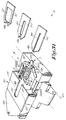
- figure 1 schematically represents a part of the device according to the invention in perspective;
- figures 2 to 10 show sections according to line II-II in figure 1, for different positions;
- figure 11 shows a section according to line XI-XI in figure 9, whereby also a drive part is represented;
- figure 12 shows a variant of the part which is represented in figure 11;
- figure 13 shows a similar view as figure 1, but for a variant of the embodiment;
- figures 14 to 17 show sections according to line XIV-XIV in figure 13, for different positions;
- figures 18 to 22 show another special application, at different stages thereof;
- figure 23 shows a variant of the part which is represented in figure 13;
- figures 24 to 27 show another embodiment of the invention, for different steps;
- figure 28 shows an embodiment of a part of a device according to the invention;
- figure 29 shows a section according to line XXIX-XXIX in figure 28;
- figure 30 shows the part from figure 28 in another position;
- figure 31 shows another embodiment in perspective; figures 32 to 34 show sections according to lines XXXII-XXXII in figure 31, for different positions.
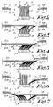
- As is shown in figure 1, the invention is related to the processing of
brushes 1 which havebrush fibres 2 of various lengths. In the example of figure 1, thebrush fibres 2 of the outermost rows offibre bundles 3 are longer than thebrush fibres 2 of themiddle field 4. - In order to be able to process
such brushes 1, in particular to be able to warp and round off thebrush fibres 2, both the long ones and the short ones, use is made of means to divide thebrush fibres 2 in different fields, so that thebrush fibres 2 can be treated separately per field. As is schematically represented in figure 1, these means according to the invention consist of the combination ofdisplacement elements 5A-5B to bend thebrush fibres 2 andauxiliary means 6A-6B to hold at least part of thebrush fibres 2 bent by thedisplacement elements 5A-5B in the bent shape. - In the embodiment of figure 1, the
displacement elements 5A-5B consist of plates which can be moved sideways which can be pressed sideways with theircrosscut ends 7 against thebrush fibres 2, such at a required height in relation to thebrush body 8 of thebrush 1. - The
auxiliary means 6A-6B also consist of plates which are situated and/or can be situated on either side of abrush 1 provided in thedevice 9, and which can be moved sideways towards one another, and which thus can also be put in contact with thebrush fibres 2 with theirends 10. In the embodiment of figure 1, theauxiliary elements 6A-6B are situated immediately under thedisplacement elements 5A-5B. - The shapes of the
ends brush 1 concerned, as is clearly visible in figure 1. - The working of the
device 9, as well as the method used hereby, is represented step by step in figures 2 to 10 and is mainly as follows. - Figure 2 shows the initial position, whereby the
displacement elements 5A-5B and theauxiliary elements 6A-6B are situated next to thebrush 1, at the height of thebrush fibres 2, for example at a certain height A. - As is shown in figure 2, we start here in the initial position with fibres which already have different lengths after the filling, which implies that the filling machine has used fibres of different lengths. However, this is not absolutely necessary: the fibres can all have the same length before the displacement is started. Moreover, after the filling, the fibres can either stay unwarped before the displacement starts, or they can be warped before the displacement starts, so that all fibre ends lie in one single field. The latter can be particularly interesting when fibre fields must be warped and/or rounded off at different lengths and when these fibre fields do not consist of individual fibre bundles, but when the fibre fields extend over parts of fibre bundles, for example 1/2 or 3/4 of certain fibre bundles; this implies that a part of the brush fibres of a fibre bundle belongs to the first level, whereas the remaining brush fibres of the same bundle belong to one or several different levels.
- As a first step, the
displacement element 5A is pulled out, whereby at least thelonger brush fibres 2 are pushed away. Thisdisplacement element 5A is hereby moved until a position is reached in which only thelonger brush fibres 2, with slantinglybent ends 11, extend from under saiddisplacement element 5A, as is represented in figure 3. In order to bring theends 11 somewhat more outside sideways, thedisplacement element 5A can possibly be shifted somewhat towards thebrush body 8, for example at a distance B, as is represented in figure 4. - Figure 5 shows how the
auxiliary element 6A is positioned above thefree ends 11, after which, as in figure 6, thedisplacement element 5A can be pulled back. In order to obtain an even better separation, theauxiliary element 6A can hereby be moved downward at a distance B from thebrush body 8. - Next, an almost identical scenario is carried out in the other direction, whose steps can be easily derived from figures 7, 8 and 9.
- Finally, a situation is achieved as represented in figure 9, whereby the
longest brush fibres 2 are pushed away sideways and are being held under theauxiliary elements 6A-6B. - In this manner is obtained a clear separation between two fields, in this case the field consisting of the
longest brush fibres 2 and the field consisting of theshortest brush fibres 2. In particular, it is now possible to process theends 12 of theshortest brush fibres 2 without hereby hindering thelongest brush fibres 2. As is schematically represented in figure 9, the invention is mainly designed to carry out treatments, such as warping and rounding off thebrush fibre ends 11, by means of awarp station 13 and a rounding offstation 14 known as such. However, it is clear that the invention can also be used in combination with other final processings. - Subsequently, the
longest brush fibres 2 are released again, so that they can also be represented to thewarp station 13 and the rounding offstation 14 as represented in figure 10. - The
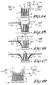
displacement elements 5A-5B and theauxiliary elements 6A-6B are of course equipped with the necessary drive means. It is clear that they can be of different nature. By way of example, two embodiments thereof are represented schematically in figures 11 and 12, in particular of the drive means 15 to move theauxiliary elements 6A-6B. - According to figure 11, use is made of
auxiliary elements 6A-6B which are made in the shape of carriages which can be moved by means ofdrive elements 16. - According to figure 12, use is made of rotatable
auxiliary elements 6A-6B which can be moved by means of adrive element 17. - It is clear that analogous drive means can be designed for the
displacement elements 5A-5B. - Figure 13 shows a variant in which a
displacement element 5C is used which mainly consists of a standingwall 19 which extends in relation to theinsertion field 18 of thebrush 1 to be treated. The shape of thewall 19 is preferably adjusted to the design of the brush fields of thebrush 1. According to the most preferred embodiment, thedisplacement element 5C, and in particular thewall 19, is also made in the shape of a ring as represented in figure 13, one and other such that twoopposite edges brush fibres 2, whereby these edges have the same function as the above-mentionedcrosscut edges 7 of thedisplacement elements - The working of the
device 9 of figure 13 is schematically illustrated in figures 14 to 17. As is represented in figure 14, thedisplacement element 5C is moved sideways by thebrush fibres 2 until the above-mentioned ends 11 of a number of thelongest brush fibres 2 are bent sideways, such that they can be picked up and held by theauxiliary element 6B as represented in the figures 15 and 16 and analogous to the figures 8 and 9. - Subsequently, this cycle is repeated in the other direction, as is schematically indicated by means of an arrow in figure 16.
- Finally, a situation is reached as in figure 17, which mainly coincides with that of the above-mentioned figure 9, after which a number of final processings can be done to the
smallest brush fibres 2 in an analogous manner. - The use of a
displacement element 5C, which consists of a standingwall 19, and preferably in the shape of a ring, is advantageous in that once the wall has moved through a brush field, thebrush fibres 2 concerned immediately spring back after said wall has passed, thanks to the limited thickness of thewall 19, and thus do not remain pushed back all the time, which in certain cases, depending on the type ofbrush fibres 2, could lead to permanent distortions. - When different fields must be separated one after the other, it is clear that one will hereby proceed systematically as a function of the way in which these fields differ. As mentioned in the introduction, preference is given to a method whereby all
brush fibres 2 save the shortest are displaced and retained first, while the shortest are being processed, after which these steps are successively repeated each time for thebrush fibres 2 which follow in length. This is illustrated in the schematic representations of figures 18 to 22. - Figure 18 shows how all
brush fibres 2, to the exception of the shortest, can be displaced by means of adisplacement element 5C. Since the displacement itself is carried out in a similar manner as is represented in figures 14 to 17, not all steps are represented here. - By repeating the
steps 14 to 17 on thebrush 1 of figure 18, whereby thedisplacement element 5C is each time represented at a different height, the situations of figures 19 to 22 can successively be reached, which makes it possible to successively provide for a final processing of thebrush fibres 2 of different lengths. - It should be noted that the
auxiliary elements - However, this does not exclude that the
auxiliary elements 6A-6B can be adjusted in said and the preceding embodiments between more than two positions. - It is clear that the
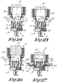
device 9 according to the invention, possibly with a suitable design of thedisplacement elements 5A-5B-5C and of theauxiliary elements 6A-6B, is particularly suitable for pushing away rows of fibres or groups of fibres which can have any contour or shape whatsoever. In order to illustrate this, a variant of the embodiment of figure 13 is represented by way of example in figure 23, which is meant to be used withbrushes 1 with a circular brush field.Such brushes 1 are used for example as a rotating brush head in an electric tooth brush. Thewall 19 is hereby circular and the crosscut ends 10 are semi-circular. - Figures 24 to 27 show a variant which is particularly suitable for
brushes 1 with a circular fibre field, but which, with an adjusted design, could also be used forbrushes 1 with brush fields in other shapes. What is special here, is that use is made of adisplacement element 5D which is mainly formed of an elastic part which can be spread sideways by means of aplunger 21 which can be moved in this elastic part. Thedisplacement element 5D is hereby held in ahead 22 which makes it possible to bring thedisplacement element 5D along the free ends of thebrush fibres 2 between thesebrush fibres 2, by means of a mutual shift between thishead 22 and thebrush 1. - The
displacement element 5D preferably has a profilededge 23 which partly causes the spreading of thebrush fibres 2 that touch it. - The successive steps of the working are illustrated in figures 24 to 27.
- In a first step, the
head 22 and thebrush 1 are presented on top of one another, as shown in figure 22. In a next step, which is represented in figure 25, thehead 22 and thebrush 1 are moved mutually towards one another, for example due to the shift of thehead 22, until thebottommost end 24 is situated above theshortest brush fibres 2, but between thelongest brush fibres 2. By subsequently extending theplunger 21, thedisplacement element 5D is spread elastically and thelongest brush fibres 2 are also pressed out by theedge 23, as is represented ni figure 26. By making thehead 22 lower further, as is represented in figure 27, thelongest brush fibres 2 are bent further outward, as they are bent around against the profilededge 23. Next, thebrush fibres 2 can be retained by means ofauxiliary elements 6A-6B, thehead 22 with thedisplacement element 5D can be removed again and the final processing of the shortest brush fibres, such as warping and rounding off, can be carried out. - As mentioned in the introduction, the
brushes 1 are preferably moved in a transport device, whereby the fibres to be processed are each time successively presented to a warp station and a rounding off station, and preferably, thebrush fibres 2 are displaced by means of displacement elements, for example 5A and 5B, which are erected next to the transport device on the one hand, and thebrush fibres 2 are retained by means ofauxiliary elements 6A-6B which move along with the transport device on the other hand. This offers the advantage that thebrush fibres 2, each time after the displacement by the auxiliary elements concerned, for example 6A-6B, can be permanently retained until they have been presented both to the warp station and to the rounding off station. - Also, figures 28, 29 and 30 show an embodiment in which the auxiliary means 6A and 6B as well as the drive means 15 thereof are mounted on such a
transport device 25, which for example consists of an endless chain, and are controlled by means of a cam drive. - The
brush 1 is hereby clamped in aclamp 26 mounted on thetransport device 25, with clamping shoes 27-28-29 as is known among others from EP. 0.078.569. - The
auxiliary elements 6A-6B are mounted in a rotating manner on thetransport device 25, whereby they can rotate around pivots 31A-31B by means of rollingarms 30A-30B. The drive means 15 to activate theauxiliary elements 6A-6B are formed of acarriage 32 which can act on the rollingarms 30A-30B by means of pressure rolls 33A-33B and can thus push theauxiliary elements 6A-6B towards one another against the force of aspring 34. - The
carriage 32 is activated by means of acam guide 35. The contact between thecarriage 32 and thecam guide 35 is hereby ensured by means ofsprings 36. - Each
clamp 26 is equipped with such drive means 15. - The working can be easily derived from figures 28 to 30. Figure 28 shows the initial situation.
- As a first step, the
brush fibres 2 concerned, in this case thelongest brush fibres 2, are spread by means of displacement elements, in this case 5E and 5F, as represented in figure 29. These displacement elements are situated for example frontally above thebrush 1. - When the
carriage 32 as represented in figure 30 is moved, by means of thecam guide 35, theauxiliary elements brush fibres 2 concerned, analogous to figure 12. - Due to the movement of the
transport device 25, eachbrush 1 can then be brought under thewarp station 13 and the rounding offstation 14. - Figure 31 shows another special embodiment with which brushes 1 can be made which have a
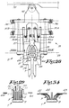
brush part 37 with a stepped profile in the longitudinal direction, either or not combined with afibre island 38, which for example defines yet another fibre level. - The
device 9 of figure 31 is characterized in that this device has at least one displacement element, but in this case several ones, in particular 5G-5H-5I, whereby each displacement element consists of a plate-shaped element which is provided with a recess, 39-40-41 respectively; in that the plate-shaped element is provided with drive means which are not represented in the figure, so as to put it sideways in contact with thebrush fibres 2 of abrush 1 put in thedevice 9, such thatcertain brush fibres 2 are bent, whereas other,shorter brush fibres 2, are each time put through the recess 39-40-41 concerned; in that it has an auxiliary element 6C with two plate-shaped parts 42-43 which are situated at a fixed distance from one another, in between which is provided aslot 44 of a certain width; and in that the auxiliary element 6C is provided with drive means, such as acarriage 45, which make it possible to shift this auxiliary element 6C in the longitudinal direction of the above-mentionedslot 44, over thedisplacement element 5G or 5H or 5I which at that time is put in contact with thebrush fibres 2. - Hereby, the working is based on the principle as represented in figures 32 to 34. First, the
displacement element 5G is slid in thebrush fibres 2. As a result, only the brush fibres which fit in therecess 39 remain standing, whereas theother brush fibres 2 are bent under thedisplacement element 5G and are thus separated and pushed away from thebrush fibres 2 which are situated in therecess 39. - At the front of the
recess 39 is provide arib 46 which is placed exactly against thefibre island 38 and pushes it entirely away in the longitudinal direction. - Once this position is reached, the
carriage 45 is shifted in the direction of thebrush 1, which results in a situation as represented in figure 33. - Afterwards, the
displacement element 5G can be shifted away again, which results in the condition of figure 34. - At that instant, the
clamp 26 with thebrush 1 provided in it can be moved and can be presented to a warp station and a rounding off station, whereby theshortest brush fibres 2 can then be treated without any hindrance from thelongest brush fibres 2, as only theshortest brush fibres 2 protrude through theslot 44, whereas all theother brush fibres 2 are held at the edges of theslot 44 under the auxiliary element 6C. - After the shortest fibres have been treated, the entire cycle is repeated, in this case two more times, whereby the displacement elements 5H and 5I are respectively used.
- Finally, the
fibre island 38 will be presented under the warp station and the rounding off station. - It should be noted that the auxiliary element 6C can cooperate with all three
displacement elements 5G-5H-5I. - It is clear that the auxiliary element 6C has two functions, on the one hand retaining the
brush fibres 2 which are bent by adisplacement element 5G-5H-5I in a certain position, and on the other hand bringing thebrushes 1 from one processing station to another one without any mixing of fields or levels with other fields or levels being possible. - The fact that the
auxiliary elements 6A-6B or 6C move along offers the advantage that the same number of fibres is presented under thewarp station 13 as under the subsequent rounding offstation 14. - It is clear that, according to a variant, the displacement elements can also move along with the transport device and that each brush clamp is provided in this case with moving displacement elements as well as auxiliary elements.
- It is also clear that all the above-mentioned devices can also be used to split up the brush fibres of brushes with equal lengths in fields.
- The present invention is by no means limited to the embodiments described as an example and represented in the accompanying drawings; on the contrary, such a method and device for processing brushes, in particular for separating brush fibres in different fields, can be made according to all sorts of variants while still remaining within the scope of the invention.
Claims (18)
- Method for processing brushes, whereby the brush fibres (2) of these brushes (1) are divided in clearly separated fields and are subsequently treated separately per field, characterized in that the brush fibres (2) are divided in separate fields by subsequently displacing a number of the brush fibres (2) by bending them by means of one or more displacement elements (5A to 5I), by retaining at least part of the displaced brush fibres (2) in bent condition by means of one or more auxiliary elements (6A-6B-6C), and by redrawing the displacement elements (5A to 5I).
- Method according to claim 1, characterized in that the displacement elements (5A to 5I) are put in contact with the brush fibres (2) by moving them sideways, either or not followed by a movement towards the brush body (8).
- Method according to claim 2, characterized in that the displacement elements (5A to 5I) are moved until only the brush fibres with slantingly bent ends (11) to be retained by the auxiliary elements (6A-6B) extend under the displacement elements (5A to 5H).
- Method according to claim 3, characterized in that the auxiliary elements (6A-6B), after the above-mentioned movement of the displacement elements (5A-5I), are presented above the above-mentioned ends (11) in relation to the brush (1) and are possibly also moved towards the brush body (8).
- Method according to any of the preceding claims, characterized in that the brush fibres (2) are displaced and retained repeatedly in two opposite directions and in that a division in fields in both halves of a brush (1) is thus obtained.
- Method according to any of the preceding claims, characterized in that use is made of a displacement element (5D) which can be spread sideways and in that this displacement element (5D) is originally placed along the free ends (11-12) of the brush fibres (2) between these brush fibres (2), after which the displacement element (5D) is spread.
- Method according to any of the preceding claims, characterized in that use is made of displacement elements (5A to 5I) and auxiliary elements (6A-6B-6C) which are adjusted to the shape of the fields to be separated.
- Method according to any of the preceding claims, characterized in that brushes (1) are taken with brush fibres (2) of equal lengths.
- Method according to any of claims 1 to 7, characterized in that brushes (1) are taken with brush fibres (2) which define fields of different levels.
- Method according to claim 9, in particular with brushes (1) with brush fibres (2) of at least three different lengths, characterized in that the displacement, retaining and processing is carried out systematically, whereby all brush fibres (2), to the exception of the shortest, are displaced and retained, while the shortest are treated, after which these steps are each time successively repeated, whereby the brush fibres (2) of each time a somewhat longer length are step by step released for treatment.
- Method according to any of the preceding claims, characterized in that the brushes (1) are moved in a transport device (25), whereby the brush fibres (2) to be treated each time are at least provided under a warp station (13) and a rounding off station (14); in that the brush fibres (2) are displaced by means of displacement elements (6A-6B-6C) which are erected next to the transport device (25); in that the brush fibres (2) are retained by means of auxiliary elements (6A-6B-6C) which move with the transport device (25); and in that the brush fibres (2) are permanently retained by the auxiliary elements (6A-6B-6C) each time after the displacement until they have been presented both to the warp station (13) and the rounding off station (14).
- Device for realizing the method according to claim 1, which is provided with means to divide the brush fibres (2) of a brush (1) in different fields, so as to be able to treat the brush fibres (2) separately per field, characterized in that the above-mentioned means consist of the combination of at least one displacement element (5A to 5I) to bend brush fibres (2) and at least one auxiliary element (6A-6B-6C) to hold at least a part of the brush fibres (2) bent by the displacement element (5A to 5I) in the bent shape.
- Device according to claim 12, characterized in that it has a displacement element (5A-5B) which consists of a plate which can be moved sideways which can be pressed sideways with its crosscut end (7) against the brush fibres (2).
- Device according to claim 12, characterized in that it has a displacement element (5C) which consists of a mainly standing wall (19) which extends in relation to the insertion field (18) of a brush (1) to be treated, preferably in the shape of a ring.
- Device according to claim 12, characterized in that the displacement element (5D) mainly consists of an elastic part which can be spread sideways by means of a plunger (21) which can move in this elastic part.
- Device according to any of claims 12 to 15, characterized in that it has at least two auxiliary elements (6A-6B) and in that these auxiliary elements (6A-6B) consist of plates which are situated on either side of a brush (1) provided in the device (9) and which can be moved sideways towards one another.
- Device according to claim 12, characterized in that this device (9) has at least one displacement element which consists of a plate-shaped element (5G-5H-5I) which is provided with a recess (39-40-41); in that the plate-shaped element (5G-5H-5I) is provided with drive means so as to put it sideways in contact with the brush fibres (2) of a brush (1) put in the device (9), such that certain brush fibres (2) are bent, whereas other brush fibres (2) are put through the above-mentioned recess (39-40-41); in that the auxiliary element (6C) has two plate-shaped parts (42-43) which are situated at a fixed distance from one another, in between which is provided a slot (44) with a certain width; and in that the auxiliary element (6C) is provided with drive means which make it possible to shift this auxiliary element in the longitudinal direction of the above-mentioned slot, over the displacement element (5G-5H-5I).
- Device according to claim 12, characterized in that it is provided with a transport device (25) to move the brushes (1); in that the auxiliary elements (6A-6B) are moved together with the transport device (25); and in that the auxiliary elements (6A-6B) are activated by means of a cam drive with a fixed cam guide (35).
Applications Claiming Priority (2)
| Application Number | Priority Date | Filing Date | Title |
|---|---|---|---|
| BE9500313 | 1995-04-05 | ||
| BE9500313A BE1009283A3 (en) | 1995-04-05 | 1995-04-05 | METHOD AND DEVICE FOR WORKING brushes. |
Publications (2)
| Publication Number | Publication Date |
|---|---|
| EP0736270A1 true EP0736270A1 (en) | 1996-10-09 |
| EP0736270B1 EP0736270B1 (en) | 2002-06-19 |
Family
ID=3888909
Family Applications (1)
| Application Number | Title | Priority Date | Filing Date |
|---|---|---|---|
| EP96200542A Expired - Lifetime EP0736270B1 (en) | 1995-04-05 | 1996-03-01 | Method and device for processing brushes |
Country Status (5)
| Country | Link |
|---|---|
| US (1) | US5690394A (en) |
| EP (1) | EP0736270B1 (en) |
| BE (1) | BE1009283A3 (en) |
| DE (1) | DE69621873T2 (en) |
| ES (1) | ES2181840T3 (en) |
Cited By (15)
| Publication number | Priority date | Publication date | Assignee | Title |
|---|---|---|---|---|
| WO1998058563A1 (en) * | 1997-06-24 | 1998-12-30 | Colgate-Palmolive Company | Trimming and end rounding of flexible head toothbrushes |
| WO2000010425A1 (en) | 1998-08-19 | 2000-03-02 | Coronet-Werke Gmbh | Method for quality inspection of bristles and use of said bristles |
| BE1011998A3 (en) * | 1995-07-24 | 2000-04-04 | Zahoransky Anton Gmbh & Co | Device for machining areas of brush bristles area of implementation. |
| BE1012152A3 (en) * | 1995-08-05 | 2000-06-06 | Zahoransky Anton Gmbh & Co | Method and device for profiling and the machine areas of implementation soies. |
| WO2000064308A1 (en) | 1999-04-27 | 2000-11-02 | Pedex & Co. Gmbh | Method for producing bristles and brushware comprising bristles of this type |
| BE1012830A5 (en) * | 1998-07-18 | 2001-04-03 | Zahoransky Anton Gmbh & Co | Method for producing brushes. |
| WO2001045534A1 (en) * | 1999-12-22 | 2001-06-28 | M + C Schiffer Gmbh | Method for producing brushes and device for implementing said method |
| BE1013118A3 (en) * | 1996-07-06 | 2001-10-02 | Zahoransky Anton Gmbh & Co | Device and method intended for machining zones of a brush bristle assembly |
| WO2002024026A1 (en) | 2000-09-19 | 2002-03-28 | Coronet-Werke Gmbh | Method for producing bristle products |
| BE1013898A3 (en) * | 1999-10-16 | 2002-12-03 | Zahoransky Anton Gmbh & Co | METHOD FOR MANUFACTURING BRUSHES. |
| BE1013959A3 (en) * | 2000-02-08 | 2003-01-14 | Zahoransky Anton Gmbh & Co | PROCESS FOR THE MANUFACTURE OF BRUSHES. |
| DE10015673B4 (en) * | 2000-03-29 | 2009-04-02 | Anton Zahoransky Gmbh & Co. | Device for processing a bristle field of brushes |
| WO2009121505A1 (en) * | 2008-04-01 | 2009-10-08 | G.B. Boucherie N.V. | Brush, particularly for household or industrial applications |
| EP2409598A3 (en) * | 2010-07-22 | 2012-03-21 | Braun GmbH | Method for producing a toothbrush head |
| CN106562559A (en) * | 2016-11-08 | 2017-04-19 | 桐乡市兴盛制刷机械有限公司 | Automatic reciprocating type hair flattening machine |
Families Citing this family (5)
| Publication number | Priority date | Publication date | Assignee | Title |
|---|---|---|---|---|
| AU9327398A (en) * | 1997-12-22 | 1999-07-15 | Johnson & Johnson Consumer Companies, Inc. | Toothbrush and method of making the same |
| BE1012603A3 (en) * | 1999-03-10 | 2001-01-09 | Boucherie Nv G B | METHOD AND APPARATUS FOR FORMING FIBER PACKAGES FOR BRUSH PRODUCTION FROM A fiber strand. |
| US6439669B1 (en) * | 1999-08-31 | 2002-08-27 | Gillette Canada Company | Filament gripper |
| US7478959B2 (en) | 2002-09-05 | 2009-01-20 | Colgate-Palmolive Company | Oral care toothbrush |
| USD660599S1 (en) * | 2009-02-05 | 2012-05-29 | Colgate-Palmolive Company | Toothbrush |
Citations (2)
| Publication number | Priority date | Publication date | Assignee | Title |
|---|---|---|---|---|
| EP0458999A1 (en) * | 1990-05-31 | 1991-12-04 | G.B. Boucherie N.V. | Device for cutting bristles of tooth brushes to different lengths in different selected areas of a tuft pattern |
| EP0639340A1 (en) * | 1993-07-21 | 1995-02-22 | JOHNSON & JOHNSON CONSUMER PRODUCTS, INC. | Device for selective separation of toothbrush bristles and device for selective cutting of toothbrush bristles |
Family Cites Families (2)
| Publication number | Priority date | Publication date | Assignee | Title |
|---|---|---|---|---|
| EP0078569B1 (en) * | 1981-11-04 | 1988-01-07 | G.B. Boucherie, N.V. | Device for separating rows of brush hairs |
| US5472263A (en) * | 1993-09-06 | 1995-12-05 | Firma Anton Zahoransky | Apparatus for profiling bristle fields |
-
1995
- 1995-04-05 BE BE9500313A patent/BE1009283A3/en not_active IP Right Cessation
-
1996
- 1996-03-01 EP EP96200542A patent/EP0736270B1/en not_active Expired - Lifetime
- 1996-03-01 DE DE69621873T patent/DE69621873T2/en not_active Expired - Lifetime
- 1996-03-01 ES ES96200542T patent/ES2181840T3/en not_active Expired - Lifetime
- 1996-04-03 US US08/627,034 patent/US5690394A/en not_active Expired - Lifetime
Patent Citations (2)
| Publication number | Priority date | Publication date | Assignee | Title |
|---|---|---|---|---|
| EP0458999A1 (en) * | 1990-05-31 | 1991-12-04 | G.B. Boucherie N.V. | Device for cutting bristles of tooth brushes to different lengths in different selected areas of a tuft pattern |
| EP0639340A1 (en) * | 1993-07-21 | 1995-02-22 | JOHNSON & JOHNSON CONSUMER PRODUCTS, INC. | Device for selective separation of toothbrush bristles and device for selective cutting of toothbrush bristles |
Cited By (25)
| Publication number | Priority date | Publication date | Assignee | Title |
|---|---|---|---|---|
| BE1011998A3 (en) * | 1995-07-24 | 2000-04-04 | Zahoransky Anton Gmbh & Co | Device for machining areas of brush bristles area of implementation. |
| BE1012152A3 (en) * | 1995-08-05 | 2000-06-06 | Zahoransky Anton Gmbh & Co | Method and device for profiling and the machine areas of implementation soies. |
| BE1013118A3 (en) * | 1996-07-06 | 2001-10-02 | Zahoransky Anton Gmbh & Co | Device and method intended for machining zones of a brush bristle assembly |
| WO1998058563A1 (en) * | 1997-06-24 | 1998-12-30 | Colgate-Palmolive Company | Trimming and end rounding of flexible head toothbrushes |
| BE1012830A5 (en) * | 1998-07-18 | 2001-04-03 | Zahoransky Anton Gmbh & Co | Method for producing brushes. |
| WO2000010425A1 (en) | 1998-08-19 | 2000-03-02 | Coronet-Werke Gmbh | Method for quality inspection of bristles and use of said bristles |
| WO2000064308A1 (en) | 1999-04-27 | 2000-11-02 | Pedex & Co. Gmbh | Method for producing bristles and brushware comprising bristles of this type |
| DE19918959A1 (en) * | 1999-04-27 | 2000-11-02 | Pedex & Co Gmbh | Process for processing bristles and bristle products with such bristles |
| US6773076B1 (en) | 1999-04-27 | 2004-08-10 | Pedex & Co. Gmbh | Method of mechanically splitting bristles |
| BE1013898A3 (en) * | 1999-10-16 | 2002-12-03 | Zahoransky Anton Gmbh & Co | METHOD FOR MANUFACTURING BRUSHES. |
| WO2001045534A1 (en) * | 1999-12-22 | 2001-06-28 | M + C Schiffer Gmbh | Method for producing brushes and device for implementing said method |
| US6808236B2 (en) | 1999-12-22 | 2004-10-26 | M+C Schiffer Gmbh | Method for producing brushes and apparatus for performing said method |
| BE1013959A3 (en) * | 2000-02-08 | 2003-01-14 | Zahoransky Anton Gmbh & Co | PROCESS FOR THE MANUFACTURE OF BRUSHES. |
| DE10015673B4 (en) * | 2000-03-29 | 2009-04-02 | Anton Zahoransky Gmbh & Co. | Device for processing a bristle field of brushes |
| DE10046536A1 (en) * | 2000-09-19 | 2002-03-28 | Coronet Werke Gmbh | Brushware-production method involves assembling single bristles or in groups on supports and structuring their ends by laser treatment. |
| WO2002024026A1 (en) | 2000-09-19 | 2002-03-28 | Coronet-Werke Gmbh | Method for producing bristle products |
| WO2009121505A1 (en) * | 2008-04-01 | 2009-10-08 | G.B. Boucherie N.V. | Brush, particularly for household or industrial applications |
| US8893344B2 (en) | 2008-04-01 | 2014-11-25 | Gb Boucherie Nv | Brush, in particular for household or industrial applications |
| EP2409598A3 (en) * | 2010-07-22 | 2012-03-21 | Braun GmbH | Method for producing a toothbrush head |
| WO2012011084A3 (en) * | 2010-07-22 | 2012-04-12 | Braun Gmbh | Method for producing a toothbrush head |
| CN103025200A (en) * | 2010-07-22 | 2013-04-03 | 博朗有限公司 | Method for producing a toothbrush head |
| US8651582B2 (en) | 2010-07-22 | 2014-02-18 | Braun Gmbh | Method for producing a toothbrush head |
| CN103025200B (en) * | 2010-07-22 | 2015-11-25 | 博朗有限公司 | For the production of the method for toothbrush head |
| CN106562559A (en) * | 2016-11-08 | 2017-04-19 | 桐乡市兴盛制刷机械有限公司 | Automatic reciprocating type hair flattening machine |
| CN106562559B (en) * | 2016-11-08 | 2018-06-29 | 桐乡市兴盛制刷机械有限公司 | Full-automatic reciprocating type puts down a mao machine |
Also Published As
| Publication number | Publication date |
|---|---|
| DE69621873D1 (en) | 2002-07-25 |
| US5690394A (en) | 1997-11-25 |
| BE1009283A3 (en) | 1997-01-07 |
| DE69621873T2 (en) | 2003-01-02 |
| EP0736270B1 (en) | 2002-06-19 |
| ES2181840T3 (en) | 2003-03-01 |
Similar Documents
| Publication | Publication Date | Title |
|---|---|---|
| EP0736270A1 (en) | Method and device for processing brushes | |
| EP0078569A2 (en) | Device for separating rows of brush hairs | |
| US4031585A (en) | Binding of perforated sheets | |
| US3866293A (en) | Apparatus for electrically terminating insulated conductors in insulation-piercing contact portions of an electrical connector | |
| NO159414B (en) | DEVICE FOR ATTACHING AT LEAST ONE CABLE TO A CARRIER. | |
| US4537545A (en) | Method and apparatus for aligning a pile of sheets provided with perforations for bindings | |
| EP0681797A1 (en) | Method for manufacturing brushes | |
| US5588206A (en) | Method for inserting wire-equipped terminal in connector housing | |
| US3197537A (en) | Apparatus and method for manufacturing slide fasteners | |
| DK164425B (en) | ELECTRICAL CONNECTION TERMINAL, SPECIFICALLY A so-called ISDN CONNECTOR, AND METHOD FOR PRODUCING CONTACT STRIPS THEREOF | |
| KR19990014851A (en) | System for cable connection | |
| EP0019396B1 (en) | Apparatus for, and a method of, inserting tape mounted terminals into apertures in a workpiece | |
| US4411062A (en) | Apparatus and method for terminating ribbon cable | |
| EP0628365B1 (en) | Device for bending the ends of metallic binding spirals | |
| EP0765535B1 (en) | A machine and method for producing electrical harnesses | |
| US4765044A (en) | Semiautomatic termination apparatus for ribbon cable | |
| US5324154A (en) | Binding perforated sheets | |
| US4572248A (en) | Wire shuffling apparatus and method | |
| US5289852A (en) | Reed for textile machines | |
| EP0283594A1 (en) | Holder for a credit card or the like | |
| US4156442A (en) | Locating means for co-operating with helical wires | |
| US2891585A (en) | Machine for making book binder elements | |
| US3362439A (en) | Machine for the production of spring assemblies | |
| US3383021A (en) | Apparatus for driving an elongated member through a base and bending an end portion of a projecting part of the elongated member | |
| PT98367B (en) | PROCESS AND APPARATUS FOR PROCESSING A CENTER NUMBER OF WIRE CONDUCTORS |
Legal Events
| Date | Code | Title | Description |
|---|---|---|---|
| PUAI | Public reference made under article 153(3) epc to a published international application that has entered the european phase |
Free format text: ORIGINAL CODE: 0009012 |
|
| AK | Designated contracting states |
Kind code of ref document: A1 Designated state(s): DE ES GB IT |
|
| 17P | Request for examination filed |
Effective date: 19970409 |
|
| 17Q | First examination report despatched |
Effective date: 19990520 |
|
| GRAG | Despatch of communication of intention to grant |
Free format text: ORIGINAL CODE: EPIDOS AGRA |
|
| GRAG | Despatch of communication of intention to grant |
Free format text: ORIGINAL CODE: EPIDOS AGRA |
|
| GRAG | Despatch of communication of intention to grant |
Free format text: ORIGINAL CODE: EPIDOS AGRA |
|
| GRAH | Despatch of communication of intention to grant a patent |
Free format text: ORIGINAL CODE: EPIDOS IGRA |
|
| GRAH | Despatch of communication of intention to grant a patent |
Free format text: ORIGINAL CODE: EPIDOS IGRA |
|
| GRAA | (expected) grant |
Free format text: ORIGINAL CODE: 0009210 |
|
| AK | Designated contracting states |
Kind code of ref document: B1 Designated state(s): DE ES GB IT |
|
| REG | Reference to a national code |
Ref country code: GB Ref legal event code: FG4D |
|
| REF | Corresponds to: |
Ref document number: 69621873 Country of ref document: DE Date of ref document: 20020725 |
|
| RAP2 | Party data changed (patent owner data changed or rights of a patent transferred) |
Owner name: FIRMA G.B. BOUCHERIE, NAAMLOZE VENNOOTSCHAP |
|
| REG | Reference to a national code |
Ref country code: ES Ref legal event code: FG2A Ref document number: 2181840 Country of ref document: ES Kind code of ref document: T3 |
|
| PLBE | No opposition filed within time limit |
Free format text: ORIGINAL CODE: 0009261 |
|
| STAA | Information on the status of an ep patent application or granted ep patent |
Free format text: STATUS: NO OPPOSITION FILED WITHIN TIME LIMIT |
|
| 26N | No opposition filed |
Effective date: 20030320 |
|
| PGFP | Annual fee paid to national office [announced via postgrant information from national office to epo] |
Ref country code: GB Payment date: 20040302 Year of fee payment: 9 |
|
| PGFP | Annual fee paid to national office [announced via postgrant information from national office to epo] |
Ref country code: ES Payment date: 20050223 Year of fee payment: 10 |
|
| PG25 | Lapsed in a contracting state [announced via postgrant information from national office to epo] |
Ref country code: IT Free format text: LAPSE BECAUSE OF NON-PAYMENT OF DUE FEES;WARNING: LAPSES OF ITALIAN PATENTS WITH EFFECTIVE DATE BEFORE 2007 MAY HAVE OCCURRED AT ANY TIME BEFORE 2007. THE CORRECT EFFECTIVE DATE MAY BE DIFFERENT FROM THE ONE RECORDED. Effective date: 20050301 Ref country code: GB Free format text: LAPSE BECAUSE OF NON-PAYMENT OF DUE FEES Effective date: 20050301 |
|
| GBPC | Gb: european patent ceased through non-payment of renewal fee |
Effective date: 20050301 |
|
| PG25 | Lapsed in a contracting state [announced via postgrant information from national office to epo] |
Ref country code: ES Free format text: LAPSE BECAUSE OF NON-PAYMENT OF DUE FEES Effective date: 20060302 |
|
| REG | Reference to a national code |
Ref country code: ES Ref legal event code: FD2A Effective date: 20060302 |
|
| PGFP | Annual fee paid to national office [announced via postgrant information from national office to epo] |
Ref country code: IT Payment date: 20100302 Year of fee payment: 15 |
|
| PGRI | Patent reinstated in contracting state [announced from national office to epo] |
Ref country code: IT Effective date: 20110616 |
|
| PGRI | Patent reinstated in contracting state [announced from national office to epo] |
Ref country code: IT Effective date: 20110616 |
|
| PGFP | Annual fee paid to national office [announced via postgrant information from national office to epo] |
Ref country code: DE Payment date: 20150303 Year of fee payment: 20 |
|
| REG | Reference to a national code |
Ref country code: DE Ref legal event code: R071 Ref document number: 69621873 Country of ref document: DE |