EP0735913B1 - Appareil et procede pour pomper et separer un melange de gaz et de liquide - Google Patents
Appareil et procede pour pomper et separer un melange de gaz et de liquide Download PDFInfo
- Publication number
- EP0735913B1 EP0735913B1 EP95904546A EP95904546A EP0735913B1 EP 0735913 B1 EP0735913 B1 EP 0735913B1 EP 95904546 A EP95904546 A EP 95904546A EP 95904546 A EP95904546 A EP 95904546A EP 0735913 B1 EP0735913 B1 EP 0735913B1
- Authority
- EP
- European Patent Office
- Prior art keywords
- gas
- liquid
- gas separation
- mixture
- fluid
- Prior art date
- Legal status (The legal status is an assumption and is not a legal conclusion. Google has not performed a legal analysis and makes no representation as to the accuracy of the status listed.)
- Expired - Lifetime
Links
Images

Classifications
-
- B—PERFORMING OPERATIONS; TRANSPORTING
- B01—PHYSICAL OR CHEMICAL PROCESSES OR APPARATUS IN GENERAL
- B01D—SEPARATION
- B01D19/00—Degasification of liquids
- B01D19/0042—Degasification of liquids modifying the liquid flow
- B01D19/0052—Degasification of liquids modifying the liquid flow in rotating vessels, vessels containing movable parts or in which centrifugal movement is caused
-
- D—TEXTILES; PAPER
- D21—PAPER-MAKING; PRODUCTION OF CELLULOSE
- D21D—TREATMENT OF THE MATERIALS BEFORE PASSING TO THE PAPER-MAKING MACHINE
- D21D5/00—Purification of the pulp suspension by mechanical means; Apparatus therefor
- D21D5/26—De-aeration of paper stock
-
- F—MECHANICAL ENGINEERING; LIGHTING; HEATING; WEAPONS; BLASTING
- F04—POSITIVE - DISPLACEMENT MACHINES FOR LIQUIDS; PUMPS FOR LIQUIDS OR ELASTIC FLUIDS
- F04D—NON-POSITIVE-DISPLACEMENT PUMPS
- F04D7/00—Pumps adapted for handling specific fluids, e.g. by selection of specific materials for pumps or pump parts
- F04D7/02—Pumps adapted for handling specific fluids, e.g. by selection of specific materials for pumps or pump parts of centrifugal type
- F04D7/04—Pumps adapted for handling specific fluids, e.g. by selection of specific materials for pumps or pump parts of centrifugal type the fluids being viscous or non-homogenous
- F04D7/045—Pumps adapted for handling specific fluids, e.g. by selection of specific materials for pumps or pump parts of centrifugal type the fluids being viscous or non-homogenous with means for comminuting, mixing stirring or otherwise treating
-
- F—MECHANICAL ENGINEERING; LIGHTING; HEATING; WEAPONS; BLASTING
- F05—INDEXING SCHEMES RELATING TO ENGINES OR PUMPS IN VARIOUS SUBCLASSES OF CLASSES F01-F04
- F05B—INDEXING SCHEME RELATING TO WIND, SPRING, WEIGHT, INERTIA OR LIKE MOTORS, TO MACHINES OR ENGINES FOR LIQUIDS COVERED BY SUBCLASSES F03B, F03D AND F03G
- F05B2210/00—Working fluid
- F05B2210/10—Kind or type
- F05B2210/13—Kind or type mixed, e.g. two-phase fluid
- F05B2210/132—Pumps with means for separating and evacuating the gaseous phase
-
- Y—GENERAL TAGGING OF NEW TECHNOLOGICAL DEVELOPMENTS; GENERAL TAGGING OF CROSS-SECTIONAL TECHNOLOGIES SPANNING OVER SEVERAL SECTIONS OF THE IPC; TECHNICAL SUBJECTS COVERED BY FORMER USPC CROSS-REFERENCE ART COLLECTIONS [XRACs] AND DIGESTS
- Y10—TECHNICAL SUBJECTS COVERED BY FORMER USPC
- Y10S—TECHNICAL SUBJECTS COVERED BY FORMER USPC CROSS-REFERENCE ART COLLECTIONS [XRACs] AND DIGESTS
- Y10S494/00—Imperforate bowl: centrifugal separators
- Y10S494/90—Imperforate bowl: centrifugal separators involving mixture containing one or more gases
Definitions
- the present invention relates to an apparatus and a process for separating a gas such as air from a liquid or a liquid suspension such as water or papermaking stock in connection with pumping said liquid.
- the invention also relates to the use of the apparatus for pumping backwater draining through a forming fabric of a paper machine, for pumping fluid material separated by flotation and for removing air from papermaking stock.
- gas enclosed or generated in a fluid to be pumped causes problems.
- the gas disturbs the pumping.
- the gas separating from the fluid under the influence of the centrifugal forces in the pumping chamber forms a gradually growing gas bubble, which decreases the power of the pump until the bubble finally is discharged.
- Such irregular function causes great disturbances.
- backwater drained through a forming fabric in a papermaking process normally, contains a large amount of enclosed air. Since the short circulation of a paper-machine requires a particularly constant flow, disturbing air is normally removed by conducting the drained backwater, by means of special pipe or channel systems, from the dewatering box or boxes to an open backwater tank, from where it is pumped back to the fibre process of the short circulation preceding sheet forming.
- Air contained in thin stock of a papermaking process also disturbs the stability of flow in the short circulation and disturbs the forming of a paper sheet by causing voids or holes in the sheet and by retarding the drainage of water.
- backwater tanks and other parts of the system are traditionally designed for very low flow speeds in order to provide sufficient time for the enclosed air to emerge and be removed before the backwater is pumped into the closed part of the short circulation. It is also common to incorporate separate deaeration devices into the short circulation in order to remove air which has not been removed from the back water or brought into the short circulation together with the stock.
- Pumps which are able to separate gas from a fluid to be pumped are well known as such, but the objective of such pumps is normally just to remove a sufficient portion of the gas to enable regular pumping.
- the known pumps are normally not capable of removing enough gas for achieving the degree of freedom of air, which is required for using the fluid directly for example in a papermaking process without further deaeration.
- Deaerating pumps have also been designed for the treatment of fibre suspensions with a rather high solids content and high viscosity. In such pumps the separation of gas is generally caused by high shear forces required for fluidizing the highly viscous fluid which is to be pumped.
- WO 92/03613 discloses a stock feeding arrangement and process wherein a fibre suspension is pumped by means of "modified" versions of the MC-pumps mentioned above. However, the specification does not explain how these pumps are to be modified.
- US-A-4,908,048 discloses a method for degassing a liquid under the action of centrifugal forces.
- the apparatus includes a rotor, wherein the separated liquid is collected in a rotating annular chamber.
- Patents such as US 2,575,568, US 3,203,354, US 3,323,465, US 3,856,483, US 4,201,555, US 3,942,961, US 4,600,413, EP 430636, WO 90/13344 and WO 93/01875.
- Co-pending patent applications FI 922283 and WO 93/23135 by the same inventor disclose a gas separating pump capable of separating air and water from a mixture thereof.
- Said pump comprises a hollow stationary shell and a central rotor having vanes rotating close to the wall of said shell for causing said mixture to rotate in a thin fluid layer along the large gas separation surface provided by said stationary shell wall.
- gas separates from the liquid and is collected in the center of the apparatus.
- said apparatus provides an improvement over previously known gas separating pumps, it is not suitable for separating gas from more viscous fluids such as papermaking stock.
- some foaming may take place as the vanes drag the liquid along a stationary surface. Dragging the liquid along said surface also consumes energy.
- the object of the present invention is to improve the function of known processes and apparatuses in order to enable an essentially complete separation of gas from a liquid or a liquid suspension.
- An object of the invention is also to provide the liquid or liquid suspension to be pumped essentially free of gas and the gas essentially free of liquid.
- An object of the invention is to provide a technically simple and energy efficient pump which can remove gas such as air essentially totally from a low viscosity liquid such as water or a higher viscosity liquid or liquid suspension such as papermaking stock and separate the liquid or suspension essentially completely from the removed gas.
- An object of the invention is further to provide a pump which does not influence the incoming flow of fluid to the pump and which is substantially self adjusting according to the incoming flow within a function range.
- An object of the invention is further to provide a self adjusting gas separating pump, the function range of which can easily be adjusted by adjusting its speed of rotation.
- An object of the invention is further to provide a gas separating pump, which can be connected to a vacuum source, and particularly so that the pump can be connected between the vacuum source and the suction object.
- An object of the invention is also to provide a means for extinguishing foam and to pump foaming liquid while separating gas from said the liquid.
- the object of the invention is further to provide a process and apparatus for separating gas in combination with pumping.
- the object of the invention is to enable fast and controlled recycling of backwater of a paper or board forming process to the fibre process without the need for a separate deaeration.
- Another object of the invention is to enable air separation and controlled processing of fluid material separated by flotation.
- An object of the invention is also to enable air separation from papermaking stock before its introduction into the short circulation, thereby rending superfluous separate deaeration devices.
- the present invention is defined in the appended claims and basically it relates to an apparatus for pumping a fluid mixture of a gas and a liquid or a liquid suspension and for separating said gas and said liquid or suspension from each other, said apparatus having a stationary fluid inlet at one end and at the opposite end a stationary pump housing with a liquid outlet and, between said inlet and said pump housing, a hollow elongated gas separation part of an essentially circular cross-section with a generally central outlet for separated gas, said apparatus including at said inlet end means for causing said mixture to rotate, while said opposite end of said apparatus widens into a pumping zone having a diameter which is larger than the diameter of the gas separation part immediately upstream thereof, said apparatus being characterized in that said gas separation part is provided by a hollow rotor between said inlet and said pump housing, the inner wall of said rotor providing a large rotatable gas separation surface.
- the rotor of the apparatus according to the present invention preferably has a generally tubular configuration and comprises at its outlet end a significantly larger diameter pumping zone extending into said pump housing.
- the best performance is generally obtained with an embodiment, wherein said rotor at the inlet has blades for rotating said incoming mixture and at the outlet ends in a larger diameter blade wheel extending into said pump housing.
- the gas outlet may be connected to a vacuum source to provide vacuum in the gas separation part or upstream of the gas separating pump.
- the present invention also relates to a process for pumping a fluid mixture of a gas and a liquid or a liquid suspension so that said gas and said liquid or suspension separate from each other, said process comprising the steps of feeding said fluid mixture into a gas separation pump having between a stationary fluid inlet and a stationary liquid outlet a hollow rotatable elongated gas separation part with an inner wall of an essentially circular cross-section; bringing said mixture into rotation at the inlet end of said gas separation pump for causing said mixture to flow towards the wall thereof; maintaining said mixture in rotation by rotating said gas separation part; causing said mixture to flow along a rotating gas separation surface formed by the wall of said gas separation part to form a fluid layer on said gas separation surface; maintaining said flow on said rotating gas separation surface for a sufficient time to allow said gas to separate from said liquid or liquid suspension and to form a gas column at the center of said gas separation part; causing said separated liquid or liquid suspension to flow along said rotating gas separation surface into a stationary pump housing having a pumping zone with a diameter larger than said gas
- said fluid mixture comprises essentially a mixture of air and water which are substantially completely separated from each other.
- said mixture is made to flow in an essentially stable flow on said gas separation surface to form a fluid layer thereon.
- the thickness of said layer is preferably less than 1/4 of the diameter of said gas separation part, more preferably less than 1/6 of said diameter. In separating air and water the fluid layer will generally be even thinner than 1/6 of said diameter.
- the fluid layer has an open surface, and the flow thus corresponds to the flow in an open channel.
- the layer thickness is chosen and set to cause the flow to be either rapid or tranquil in the gas separation part.
- a controlled transition from rapid to tranquil flow is preferably arranged before the fluid enters the pumping zone.
- a preferred embodiment of the process is provided by connecting the gas discharge to a vacuum source which may be used either to improve the effect of gas separation in the pump or as a means of suction in a process upstream of the pump.
- a vacuum source which may be used either to improve the effect of gas separation in the pump or as a means of suction in a process upstream of the pump.
- the process according to the invention is basically self-adjusting. However, at need the depth of said liquid ring is adjusted by means of adjusting the speed of rotation.
- foam floating on the gas separation surface is extinguished by spraying fluid into the central gas column.
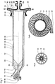
- the gas separation pump comprises an essentially hollow tubular rotor 12 with a stationary fluid inlet 14 at one end 18 and a stationary pump housing 16 at the opposite end 22.
- a set of blades 20 extending from the rotor wall towards the center of said rotor 12.
- a blade wheel 24 with blades 42.
- the pump housing 16 has an outlet for gas and peripheral liquid discharge pipe 28.
- the central part of said rotor 12 forms a rotatable elongated tubular gas separation part 30, the inner wall of which provides a large separation surface 32.
- the gas separation part 30 shall, according to the invention, be sufficiently long for allowing sufficient time for the fluid fed through inlet 14 and any possible sprays resulting from the action of blades 20 at the inlet end 18 of the apparatus to settle at said separation surface 32, and for any gas enclosed in said fluid to separate, as said fluid flows from inlet to outlet in said rotor 12.
- the diameter of separation part 30 should be relatively small compared to the length of said separation part 30.
- the separation part 26 should have a diameter D which is smaller than the length L of said separation part.
- Said diameter D should preferably be smaller than half the length L.
- a preferred ratio of D to L is from less than 1:2 up to 1:20 or more.
- the gas separation surface shall, according to the invention, be sufficiently large for allowing the fluid in said rotor 12 to settle in a fluid layer 34 on the surface 32 of said gas separation part 30. In said thin fluid layer 34 the distance for the gas to reach the surface 36 of the fluid is short and an effective gas separation will take place.
- the separated gas forms a gas column 38 surrounded by said fluid surface 36.
- Said layer 34 gradually releases all contained gas and transforms into a gas free layer of liquid or liquid suspension.
- said blades 20 are at this point preferably shaped in a spiral form which follows the natural flow path of the fluid when accelerating.
- said rotor 12 enlarges smoothly into a pumping zone 17 having a blade wheel 24.
- the separated liquid or liquid suspension (hereinafter for short referred to merely as "liquid") forms a deeper liquid ring 40 in said blade wheel 24 which causes the accumulating pressure at the periphery of the pump housing 16 to increase and the liquid, now essentially free of gas, to be discharged through liquid discharge pipe 28.
- a controlled transition from rapid to tranquil flow may be obtained by the insertion of a threshold ring (not shown) on the gas separation surface 32 at the portion where said transition is desired.
- the gas separation pump according to the invention is thus self adjusting within certain limits.
- the pressure of the pumped liquid can also be adjusted by adjusting the rotational speed of the rotor 12, and thus the range of self adjustment can be set to meet prevailing operating conditions.
- the separation part 30 smoothly transforms into a larger diameter pumping zone 17 without any distinct transition point.
- the diameter of said pumping zone 17 is preferably significantly larger than the diameter of the gas separation part 30 so that a distinct widening of the apparatus is provided for receiving the degassed liquid and to form a sufficiently deep liquid ring 40 to allow pumping of the liquid without disturbing the surface of said liquid ring.
- the rotor 12 enlarges smoothly like a funnel from a separation part 30 to a pumping zone having a blade wheel 24. Thanks to the smooth construction the liquid layer 34 will flow without disruption from separation part 30 to pumping zone 17. A violent transition might cause a disruption of the laminar flow and cause gas to mix into the liquid already freed from gas.
- the geometrical shape of the separation part 30 is not limited to this form.
- the invention functions also if the separation part is shaped like a cone or has an intermediary shape.
- the blade wheel 24 has an end shield 49 for preventing the stationary back wall of pump housing 16 from generating turbulence in liquid ring 40.
- Said end shield 49 is provided with holes 47 permitting the liquid pressure building up between end shield 49 and back wall 41 to be discharged into liquid ring 40.
- the gas column 38 should occupy a significant portion, preferably not less than half of the available volume of the gas separation part 30 of rotor 12.
- the fluid layer 34 should remain relatively thin, preferably less than one fourth and even more preferably below one sixth or less of the diameter D of the gas separation part, whereby the centrifugal forces cause only a modest pressure build up in said fluid layer 34, and excessive compression of the gas bubbles enclosed in said fluid layer is avoided.
- the diameter of the pumping zone 17 and blade wheel 24 are preferably significantly larger than that of gas separation part 30. Even if the most preferred embodiment as presented in Fig. 1, is the one wherein the fluid layer 34 in separation part 30 is shallow compared to the liquid ring 40 in pumping zone 17, the invention functions also if the difference in depth between separation part 30 and pumping zone is smaller.
- a central gas outlet 26 through which the gas accumulating in gas column 38 is removed.
- the gas is always removed from the gas column 38 and preferably at the pump housing 16, where the liquid has essentially totally been separated from the gas.
- the gas outlet may alternatively be arranged centrally or decentrally through the pump housing 16 or through a tubular shaft of rotor 12 through either end. According to the invention, even a counter flow gas removal through inlet 14 is possible.
- the rotor 12 is driven (by driving means not shown) by a shaft 44 at said inlet end 18.
- Said shaft 44 extends through said inlet 14 in bearing 46.
- At the opposite end said blade wheel 24 extends into a bearing 48 incorporated into pump housing 16.
- the shaft 44 may be arranged to go through the entire rotor 12 and to pass through both inlet 14 and pump housing 16, or the shaft may be connected to the blade wheel 24 or otherwise to the outlet end of rotor 12 only.
- the support of rotor 12 may also be arranged at one end only or even through bearings arranged at its central part. Many technical solutions are available, as will be appreciated by those skilled in the art.
- Fig. 2a shows a section A-A of the pump of Fig. 1, which shows the preferred spiral shape of blades 20 of inlet end 18 of rotor 12.
- the spiral form of blades 20 and a tangential feeding of the mixture of gas and liquid allow a smooth acceleration of the fluid, avoiding excessive turbulence.
- spiral blades 20 cause the fluid to flow against the periphery of inlet end 18 leaving space for gas at the center of said inlet end, so that gas column 38, as can be seen in Fig. 1, extends through said blades into inlet 14.
- Fig. 2b represents a section B-B at the outlet end of the pump of Fig. 1.
- Fig 2b shows the pump housing 16 with its larger diameter, the outlet 28 which extends in a spiral form around the pump housing 16 and the liquid ring 40 formed during use in said pump housing.
- the inner diameter of the liquid ring 40 varies according to the operating conditions, remaining within certain limits in equilibrium with the rotational speed of blade wheel 24, the pressure at the outlet 28 and flow of fluid through said pump.
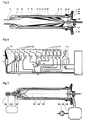
- Fig. 3 shows an embodiment of the invention corresponding largely to the embodiment of Fig. 1 but showing various optional embodiments that may be used in the construction of the apparatus according to the present invention.
- shaft 44 passes through the entire length of rotor 12.
- Bearing 46' provided at inlet end 18 is of a type which is lubricated by the inflowing fluid, such bearings being known to those skilled in the art.
- Outlet end 22 of rotor 12 is supported by blades 13 forming vanes at the downstream end of said separation part 30.
- Rotor 12 ends in a channel-like pumping zone 17 limited by an annular plate 11 attached to the blades 42 of blade wheel 24.
- the wall of said rotor 12 has an annular shoulder 29 decreasing the inner diameter of said rotor 12. Shoulder 29 allows a control of the depth of fluid layer 34 flowing along said gas separation surface 32 and hence the retention time. The bubbles may need a minimum retention time in order to unite into larger enough bubbles to penetrate all the way to the surface 36.
- labyrinth sealing 23 of a known type. Said seal 23 minimizes leakage from liquid ring 40 to the outside space. At the end of sealing 23 there is a larger ring 25 for causing liquid leaking through labyrinth sealing 23 to rotate in an exit chamber 21. A pipe 19 is provided for conducting leaking fluid from exit chamber 21 back to inlet 14. There are numerous other ways of sealing the pump housing 16, as will be obvious to those skilled in the art.
- Fig. 3 further shows a pressure sensor 74 attached to back wall 41 of pump housing 16 for sensing the pressure of liquid ring 40 in the pump.
- a process control system is indicated by box 76 and an adjustable speed drive is indicated by box 78.
- the rotational speed of rotor 12 may be adjusted accordingly so that the depth of liquid ring 40 in pump housing 16 can be kept within the limits of self control.
- Fig. 3a shows a section along line C-C in Fig. 3 wherein the hatched ring 43 indicates the span of self-adjusting inner surfaces of liquid ring 40; surface 43' indicates the biggest depth; and surface 43''indicates the smallest depth of said liquid ring.
- blades 42 of blade wheel 24 are so short that they remain completely covered by liquid ring 40.
- the blade wheel to be used in the present invention may be executed in various ways known to those skilled in the art.
- said blade wheel may have closed channels or blades open in either direction, or it may even totally lack vanes or blades.
- Fig. 4 shows another embodiment of the invention.
- the exterior of inlet 14 and pump housing 16 are connected together by a shell 15 enclosing rotor 12 in a housing.
- Said rotor 12 has an open inlet end 18 extending into a bearing incorporated into inlet 14.
- the outlet end comprises a driving shaft 45 for said rotor, the blades 42' of blade wheel 24 extending to the center of blade wheel 24.
- Gas outlet 27 extends decentrally from the wall of pump housing 16.
- gas outlet 26 or 27 is connected to a vacuum source (not shown), so that the gas cumulating in gas column 38 may be removed by suction.
- the vacuum causes the gas bubbles enclosed in the fluid layer 34 to expand, thus increasing their flow speed towards the liquid surface 36 and into gas column 38. If the applied vacuum is deep enough, it causes the liquid in fluid layer 34 to boil, whereby also dissolved gas is liberated and removed from the liquid.
- shell 15 together with inlet 14 and pump housing 16 forms a closed chamber to which vacuum can be applied through gas outlet 27, whereby the vacuum acts through outlet 27, rotor 12 and inlet 14 upstream.
- the advantages of the gas separation pump according to Fig. 4 will be especially evident when said pump is used in a paper making process and the vacuum needed for drainage at the papermaking machine forming fabric is caused by suction through the gas outlet 27 of the pump.
- the vacuum at the forming fabric can be applied either through the inlet pipe 14 or through a separate suction pipe (not shown) connected to said gas separation pump.
- a stable flow of backwater to said pump may be provided either by feeding the drained backwater to said pump through an inlet pipe so spacious that the backwater surface always remains open, or by keeping the inlet pipe constantly full of water when applying vacuum at the forming fabric through said separate suction pipe.
- Fig. 5 represents a preferred embodiment of the apparatus for separating gas and pumping the essentially gas free liquid when the fluid mixture is a foam or strongly tends to form foam.
- the apparatus is in other respects essentially similar to the embodiment of Fig 4 but the shaft 45' is hollow, constituting a feeding pipe for spraying fluid into gas column 38 through nozzles 70 arranged in the outlet end of rotor 12.
- spray nozzles may be incorporated into a shaft passing through the entire rotor or into the pump housing 16 in a way, explained in copending patent application WO 93/23135.
- a combination of different types of spray nozzles is contemplated within the scope of the present invention. Droplets 72 sprayed from the nozzles and hitting the surface 34 cause foam on this surface to collapse.
- a large rotating gas separation surface is provided in separation part 30 so that a thin rotating fluid layer 34 can be formed on said rotating surface. Gas separated by means of the centrifugal forces is collected into a distinct central gas column 38, from where it is removed.
- the large rotating separation surface is provided by the elongated separation part 30 of rotor 12 having a length substantially exceeding its diameter.
- a mixture of gas and a liquid or a liquid suspension is separated into an essentially gas-free liquid and an essentially liquid-free gas.
- the liquid is a low viscosity liquid like water or a higher viscosity liquid or suspension like fiber stock.
- the gas is air or another gas substantially lighter than the liquid component of the mixture.
- the liquid may contain fibers or impurities such as ink particles to an amount, which does not, however, make the fluid mixture excessively viscous.
- a gas/liquid mixture is fed for instance into the gas separation pump of Fig. 1 through inlet 14.
- the mixture is brought into rotation by blades 20 of rotor 12 so that it is slung onto the gas separation surface 32 formed on the inner wall of rotor 12 in gas separation part 30.
- a rotating fluid layer 34 is formed on said rotating surface.
- the lighter gas enclosed in the heavier liquid strives out from the liquid towards the center of the apparatus, forming a gas column 38.
- the heavier liquid droplets collect at the gas separation surface 32 of rotor 12 and form a liquid layer 34 on said gas separation surface.
- the enclosed gas will easily pass through the relatively thin fluid layer 34, separate from the liquid and transfer into the gas column 38 in the center of the apparatus.
- the layer thickness and flow speed in the separation part are inversely proportional and, consequently, as long as the layer is kept thin, variations in the layer thickness do not materially affect the gas separation efficiency.
- the flow speed in the gas separation part may thus be chosen according to any particular case so that any heavy material striving to settle on the gas separation surface 32 will be flushed away by the fluid flow.
- the liquid flows continuously from the inlet end 18 towards the outlet end 22 along the separation surface of the rotating separation part 30, reaching blade wheel 24 which is smoothly connected to said separation part 30.
- the diameter of rotor 12 increases at the transition between separation part 30 and blade wheel 24, whereby the rotating, now essentially gas-free liquid is pressed toward the periphery of the pump housing 16, forming a liquid ring 40 therein. Due to centrifugal forces said liquid ring 40 is pressed into liquid outlet 28, which extends as a spiral around the periphery of pump housing 16, and is discharged.
- the lighter gas correspondingly, collects into the center of the rotating apparatus, and forms a gas column 38, limited towards the rotating fluid 34 by a fluid surface 36. From this gas column 38 the gas can be removed and thus separated from the liquid.
- the gas may be discharged either through a gas outlet 26 in the pump housing 16 or through the rotor shaft in either outlet or inlet direction.
- the depth of liquid ring 40 in pump housing 16 automatically adjusts, within certain limits, to the flow of entering fluid so that a pumping pressure sufficient for pumping the liquid forward is obtained.
- the depth of the liquid ring as a function of the pressure difference can be adjusted by adjusting the rotational speed of the rotor. By adjusting the rotational speed, the depth of the liquid ring can be adjusted according to the flow of incoming gas and liquid mixture and the required pumping pressure. Within certain limits the pump is self-adjusting. Without disturbing the process, the depth of liquid ring 40 in pump housing 16 can vary within a relatively large range. As long as fluid layer 34 is not disrupted, no gas enters liquid outlet 28 and no significant amount of liquid enters gas outlet 26.
- a suction source may be connected to the gas outlet 26 for improving the gas separation.
- a suction source is particularly preferred when suction is needed at the source of the mixture of gas and liquid. Due to the open gas column 38 formed in the center of the pump being in direct connection with a void space 54 in inlet 14, the suction applied at gas outlet 27 will affect also equipment upstream of the pump. Particularly in the case when the mixture contains considerable amounts of gas, so that it rather consists of liquid droplets in an aerosol, the flow speed of the mixture can be increased by connecting suction to a pump according to the invention.
- Foam flowing into the pump or forming therein concentrates on the surface 36 of the fluid layer 34 and collapses rapidly due to the centrifugal forces, whereby the gas is liberated and strives towards the center.
- Particularly stable foam may be extinguished by directing sprays 52 of a fluid, such as a liquid, towards the surface 36 of fluid layer 34.
- Spray nozzles are designed to spray the fluid within the void space of gas column 38.
- the gas separation pump according to the present invention is especially well suited for recycling paper machine backwater into the short circulation fibre process.
- Fig 6 represents a particularly favourable use of gas separation pumps in a process according to copending patent application WO 93/23612, corresponding to granted FI Patent 89728, by the same inventor. It is obvious for the person skilled in the art that the present invention offers significant improvement also to conventional papermaking processes, by increasing recycling speed of backwater and eliminating the need for huge backwater tanks.
- the solution according to Fig. 6 represents a papermaking process, where thin stock is fed through a head box 100 onto a forming wire, for the forming of a web.
- Backwater draining through the forming wire is collected in drainage boxes 101, suction boxes 102 and the suction roll 103 and flows directly into gas separations pumps 10, 10' and 10'', according to the present invention.
- the gas separation pumps 10' and 10'' relating respectively to suction boxes and to a suction roll may be connected to a vacuum source (not shown) for providing the suction needed in said suction boxes and said suction roll.
- the gas separating pumps 10, 10' and 10'' separate the air contained in the backwater and feed the backwater as separate air free flows to various dilution points in the primary fibre process.
- Said fibre process goes from stock preparation 124 through a mixer 123, centrifugal cleaner 122, screen 121 and stock distributor 125 to the headbox 100 and further to paper web forming.
- the gas separation pumps according to the present invention thus provide means for fast and direct recycling of essentially air free backwater into the fibre process of a papermaking machine wet end.
- a part of the collected backwater is fed to a fibre recovery unit 50 which may be one designed according to co-pending patent application FI 930247 by the same inventor and incorporated herein by reference.
- fibres are separated from the backwater flow 61 by means of foaming. Clear water, essentially free from solids is discharged through clear water discharge 63 and fed out from the short circulation.
- the foam from said recovery unit is extinguished in a foam extinguisher and flows further into a gas separation pump 10''', which feeds the recovered stock 64, essentially free of air, directly into the fibre process.
- the present invention thus provides a means for separating air from the product of such a compact flotation process, providing a means the fast recycling of recovered fibres in the paper machine wet end.
- the gas separation pump according to the present invention provides a means for handling foam resulting from other flotation processes, like deinking of waste paper.
- Gas separation pumps for handling foam from flotation processes can favorably be of the type with integrated foam extinguishing, as represented by Fig. 5.
- Fig 7. represents a use of the present invention for removing air from viscous liquids like papermaking stock, when the air is more stably entrained by the fibre network.
- paper stock is fed to a gas separation pump through an automatic control valve 80, being positioned for a controlled constant flow of stock by means of flow meter 82 and process control system 84.
- the gas separation pump is set under vacuum by means of a vacuum system 86, the vacuum being such that the temperature of the stock causes the stock in liquid layer 34 to boil in the rotating gas separation part 30.
- the boiling causes air bubbles entrained in the liquid layer 34 to expand so that they are efficiently and essentially completely removed into gas column 38 and further discharged into condenser 88 of vacuum system 86, which causes the vapor evaporated by the boiling of the stock in the pump to condense.
- the air removed from the stock is removed from condenser 88 by means of vacuum pump 86.
- the deaerated stock is discharged from the pump through stock outlet 28.
- control valve 80 For the smooth and constant feeding of stock it is essential that the pressure difference of control valve 80 is kept constant, which on the pressure side of valve 80 is achieved by means well known to persons skilled in the art, and on the suction side by dimensioning the pump 86 and the condenser 88 abundant enough for granting a sufficient flow of vapor and air from the pump.
- flotation is used in other separation processes, as for example for the removing of ink particles from a fibre suspension resulting from pulping printed waste paper.
- the fibre suspension is typically 1 to 3 % such that a relatively stable fibre network results, whereas ink particles, which have been released from the fibres by mechanical and chemical means are mobile within the fibre network and are carried out from the suspension by gas bubbles transferring the same.
- the products of the deinking process are a foam containing ink particles and a suspension of deinked fibres. Both of these products contain a large amount of air and are difficult to process in prior art pumps.
- the foam containing ink may preferably be handled by a gas separation pump according to the present invention in the same manner as the fibre material recovered according to the process described above.
- the suspension of deinked fibres resulting from a deinking flotation process is typically saturated by air and the relatively stable fibre network traps the enclosed air bubbles and makes the handling thereof in gas separating pumps particularly difficult.
- the separation of gas will be only partial, but due to the huge gas separation capability and smooth flow in the pump, the pumping will be very stable and the pump will function in a self regulating manner as explained above.
- the fibre suspension can also be brought to boil, whereby the enclosed bubbles expand and a total separation of gas is obtained according to the process described above.
- the present invention has been described principally as a pump solution relating to the paper industry. It is, however, obvious for the persons skilled in the art that the pump can be used for many other purposes when gas is to be removed from a liquid or a liquid suspension, and a liquid or suspension containing gas is to be pumped substantially free of gas.
Landscapes
- Engineering & Computer Science (AREA)
- Mechanical Engineering (AREA)
- Chemical & Material Sciences (AREA)
- Chemical Kinetics & Catalysis (AREA)
- General Engineering & Computer Science (AREA)
- Paper (AREA)
- Gas Separation By Absorption (AREA)
- Degasification And Air Bubble Elimination (AREA)
- Jet Pumps And Other Pumps (AREA)
- Structures Of Non-Positive Displacement Pumps (AREA)
- Rotary Pumps (AREA)
- Centrifugal Separators (AREA)
Claims (19)
- Appareil pour pomper un mélange de fluide d'un gaz et d'un liquide ou d'une suspension liquide et pour séparer ledit gaz et ledit liquide ou suspension l'un de l'autre, ledit appareil ayant une entrée de fluide stationnaire (14) à une extrémité (18) et à l'extrémité opposée (22) un carter de pompe stationnaire (16) avec une sortie de liquide (28) et, entre ladite entrée (14) et ledit carter de pompe (16), une pièce de séparation de gaz oblongue creuse (30) d'une section transversale essentiellement circulaire avec une sortie généralement centrale (26, 27) pour le gaz séparé, ledit appareil incluant à ladite extrémité d'entrée (18) des moyens pour amener ledit mélange à tourner tandis que l'extrémité opposée (22) dudit appareil s'élargit en une zone de pompage (17) ayant un diamètre qui est plus grand que le diamètre de la pièce de séparation de gaz (30) directement en amont de celle-ci, ledit appareil étant caractérisé en ce que ladite pièce de séparation de gaz (30) est réalisée par un rotor creux (12) entre ladite entrée (14) et ledit carter de pompe (16), la paroi interne dudit rotor (12) réalisant une grande surface de séparation de gaz tournante (32).
- Appareil selon la revendication 1, où ledit rotor (12) a une configuration généralement tubulaire et comprend à son extrémité de sortie (22) ladite zone de pompage (17) qui a un diamètre nettement plus grand et qui s'étend dans ledit carter de pompe (16).
- Appareil selon la revendication 2, où le diamètre dudit rotor (12) augmente régulièrement pour former ladite zone de pompage (17) d'un plus grand diamètre, ledit rotor (12) ayant une roue à lames (24) s'étendant dans ledit carter de pompe (16).
- Appareil selon l'une des revendications 1 à 3, où ledit moyen pour amener ledit mélange à tourner comprend des lames (20) s'étendant depuis la paroi dudit rotor (12) vers le centre de celui-ci à ladite extrémité d'entrée (18).
- Appareil selon l'une des revendications 1 à 4, où ladite pièce de séparation de gaz (30) a une configuration généralement tubulaire avec un diamètre D qui est plus petit que sa longueur L, le rapport D/L étant de préférence depuis en dessous environ 1:2 à environ 1:20.
- Appareil selon l'une des revendications 1 à 5, où ladite entrée (14) et ledit carter de pompe (16) sont reliés l'un à l'autre par une coque (15) formant un espace fermé entourant ledit rotor (12).
- Appareil selon l'une des revendications 1 à 6, où ladite paroi dudit rotor (12) est pourvue d'un épaulement annulaire diminuant son diamètre interne.
- Appareil selon l'une des revendications précédentes, où des moyens (70) sont prévus pour pulvériser un fluide contre ladite surface de séparation de gaz (32).
- Appareil selon l'une des revendications précédentes, où une source de vide est reliée à ladite sortie de gaz (26, 27).
- Procédé pour pomper un mélange de fluide d'un gaz et d'un liquide ou d'une suspension liquide de façon que ledit gaz et ledit liquide ou suspension se séparent l'un de l'autre, ledit procédé comprenant les étapes consistant à :amener ledit mélange de fluide dans une pompe de séparation de gaz présentant entre une entrée de fluide stationnaire et une sortie de liquide stationnaire une pièce de séparation de gaz oblongue creuse apte à tourner avec une paroi interne d'une section transversale essentiellement circulaire ;entraíner ledit mélange en rotation à l'extrémité d'entrée de ladite pompe de séparation de gaz pour amener ledit mélange à s'écouler vers la paroi de celle-ci ;maintenir ledit mélange en rotation en faisant tourner ladite pièce de séparation de gaz ;amener ledit mélange à s'écouler le long d'une surface de séparation de gaz tournante formée par la paroi de ladite pièce de séparation de gaz pour former une couche de fluide sur ladite surface de séparation de gaz ;maintenir ledit écoulement sur ladite surface de séparation de gaz tournante pendant un temps suffisant pour permettre audit gaz de se séparer dudit liquide ou de la suspension liquide et pour former une colonne de gaz au centre de ladite pièce de séparation de gaz ;amener ledit liquide séparé ou la suspension liquide à s'écouler le long de ladite surface de séparation de gaz tournante dans un carter de pompe stationnaire ayant une zone de pompage avec un diamètre qui est plus grand que ladite pièce de séparation de gaz et amener ledit liquide à former un anneau de liquide tournant dans ladite zone de pompage ; etévacuer ledit liquide dudit carter de pompe et évacuer ledit gaz de ladite colonne de gaz.
- Procédé selon la revendication 10, où ledit mélange comprend essentiellement un mélange d'air et d'eau qui sont séparés sensiblement complètement l'un de l'autre.
- Procédé selon la revendication 10 ou 11, où ledit mélange est amené à s'écouler selon un écoulement essentiellement tranquille sur ladite surface de séparation de gaz pour former une couche de fluide d'une épaisseur qui est inférieure à 1/4 du diamètre de ladite pièce de séparation de gaz, de préférence inférieure à 1/6 dudit diamètre.
- Procédé selon l'une des revendications 10 à 12, où ledit gaz est évacué de ladite colonne de gaz par aspiration.
- Procédé selon la revendication 13, où ledit mélange de fluide est un mélange d'un gaz et d'une suspension liquide qui est amené à bouillir par un vide provoqué par ladite aspiration par quoi le gaz entraíné dans ledit mélange est retiré essentiellement complètement.
- Procédé selon la revendication 14, où ladite aspiration est appliquée à une sortie de gaz de ladite pompe de séparation de gaz et l'écoulement du fluide entrant dans ladite entrée de ladite pompe de séparation de gaz est commandée.
- Procédé selon la revendication 10, où la profondeur dudit anneau liquide est ajustée par un réglage de la vitesse de rotation.
- Procédé selon la revendication 10, où une pulvérisation de fluide est injectée vers ladite couche sur ladite surface de séparation de gaz.
- Dans un procédé pour fabriquer du papier ou du carton, le perfectionnement comprend le recyclage d'une eau évacuée par un cylindre dans une machine de fabrication de papier dans le procédé de fibres à l'aide d'une pompe de séparation de gaz selon l'une des revendications précédentes 1 à 9.
- Dans un procédé de flottaison, le perfectionnement comprend le traitement d'un produit de flottaison de fluide à l'aide d'une pompe de séparation de gaz selon l'une des revendications précédentes 1 à 9.
Applications Claiming Priority (3)
| Application Number | Priority Date | Filing Date | Title |
|---|---|---|---|
| FI935853A FI97332B (fi) | 1993-12-23 | 1993-12-23 | Laite ja menetelmä kaasun ja nesteen muodostaman seoksen pumppaamiseksi ja erottamiseksi |
| FI935853 | 1993-12-23 | ||
| PCT/FI1994/000578 WO1995017235A1 (fr) | 1993-12-23 | 1994-12-21 | Appareil et procede pour pomper et separer un melange de gaz et de liquide |
Publications (2)
| Publication Number | Publication Date |
|---|---|
| EP0735913A1 EP0735913A1 (fr) | 1996-10-09 |
| EP0735913B1 true EP0735913B1 (fr) | 1998-10-14 |
Family
ID=8539179
Family Applications (1)
| Application Number | Title | Priority Date | Filing Date |
|---|---|---|---|
| EP95904546A Expired - Lifetime EP0735913B1 (fr) | 1993-12-23 | 1994-12-21 | Appareil et procede pour pomper et separer un melange de gaz et de liquide |
Country Status (11)
| Country | Link |
|---|---|
| US (1) | US5861052A (fr) |
| EP (1) | EP0735913B1 (fr) |
| JP (1) | JP3679806B2 (fr) |
| KR (1) | KR100402468B1 (fr) |
| AT (1) | ATE172128T1 (fr) |
| AU (1) | AU1371295A (fr) |
| BR (1) | BR9408376A (fr) |
| CA (1) | CA2179729C (fr) |
| DE (1) | DE69413999T2 (fr) |
| FI (1) | FI97332B (fr) |
| WO (1) | WO1995017235A1 (fr) |
Cited By (1)
| Publication number | Priority date | Publication date | Assignee | Title |
|---|---|---|---|---|
| DE202018006038U1 (de) | 2018-07-04 | 2019-01-16 | Voith Patent Gmbh | Vorrichtung zum Entgasen eines flüssigen bis pastösen Mediums, insbesondere einer Streichfarbe |
Families Citing this family (32)
| Publication number | Priority date | Publication date | Assignee | Title |
|---|---|---|---|---|
| FI97631C (sv) * | 1994-11-21 | 1997-01-27 | Pom Technology Oy Ab | Anordning och förfarande för att sila en fibersuspension |
| DE19650407A1 (de) * | 1996-12-05 | 1998-06-10 | Kevin Business Corp | Blut-Gas-Trennverfahren und -Trennvorrichtung |
| FI105489B (fi) * | 1998-08-21 | 2000-08-31 | Ahlstrom Machinery Oy | Menetelmä ja laitteisto paperimassan esikäsittelemiseksi |
| FI111873B (sv) * | 1999-06-03 | 2003-09-30 | Pom Technology Oy Ab | Gasavskiljande centrifugal anordning, förfarande för att pumpa och avgasa en fluid samt förfarande för tillverkning av papper eller kartong |
| FI109548B (sv) * | 2000-04-19 | 2002-08-30 | Pom Technology Oy Ab | Arrangemang för rening av pappersmassa |
| FI20000939A (fi) * | 2000-04-19 | 2001-10-20 | Pom Technology Oy Ab | Rainan muodostamiseen liittyvä menetelmä ja laite |
| JP4184103B2 (ja) * | 2003-01-30 | 2008-11-19 | 株式会社小松製作所 | 気泡除去装置 |
| US7537644B2 (en) | 2003-10-24 | 2009-05-26 | Gastran Systems | Method for degassing a liquid |
| DE10356576A1 (de) * | 2003-12-04 | 2005-07-07 | Voith Paper Patent Gmbh | Verfahren zum Führen von an einer Papiermaschine offen anfallendem Siebwasser |
| FI116575B (sv) * | 2004-06-28 | 2005-12-30 | Pom Technology Oy Ab | Förfarande och anordning vid pappersmaskin |
| DE102004051327B4 (de) * | 2004-10-21 | 2007-09-27 | Voith Patent Gmbh | Verfahren zur Entgasung und Zuführung einer Faserstoffsuspension zu einem Stoffauflauf sowie Entgasungsvorrichtung |
| FI20041480A0 (fi) * | 2004-11-17 | 2004-11-17 | Pom Technology Oy Ab | Anturilla varustettu kaasua erottava keskipakoislaite |
| EP1873399B1 (fr) * | 2006-06-29 | 2012-12-05 | Grundfos Management A/S | Dispositif de pompe centrifuge |
| JP5107747B2 (ja) * | 2007-03-09 | 2012-12-26 | 富士フイルム株式会社 | 放射線画像検出器 |
| US7947112B1 (en) | 2007-07-16 | 2011-05-24 | Rheodyne, Llc | Method for degassing a fluid |
| FI20075558A0 (fi) * | 2007-07-23 | 2007-07-23 | Pom Technology Oy Ab | Erotuspumppu |
| JP4739298B2 (ja) * | 2007-08-31 | 2011-08-03 | 富士フイルム株式会社 | 放射線画像検出器 |
| DE102007060736A1 (de) * | 2007-12-17 | 2009-06-18 | Voith Patent Gmbh | Verfahren zur Entfernung von Störstoffen aus einer wässrigen Papierfasersuspension mit Hilfe mindestens einer Flotationsanlage |
| EP2199614B1 (fr) * | 2008-12-22 | 2016-09-28 | Safran Aero Boosters SA | Machine combinée de pompage et de séparation pour circuit d'huile de turboréacteur |
| US9095856B2 (en) | 2010-02-10 | 2015-08-04 | Dresser-Rand Company | Separator fluid collector and method |
| US8673159B2 (en) | 2010-07-15 | 2014-03-18 | Dresser-Rand Company | Enhanced in-line rotary separator |
| WO2012009159A2 (fr) | 2010-07-15 | 2012-01-19 | Dresser-Rand Company | Ensemble d'aubes radiales pour séparateurs rotatifs |
| WO2012012018A2 (fr) | 2010-07-20 | 2012-01-26 | Dresser-Rand Company | Séparation améliorée par détente et refroidissement combinés |
| US8821362B2 (en) | 2010-07-21 | 2014-09-02 | Dresser-Rand Company | Multiple modular in-line rotary separator bundle |
| EP2614216B1 (fr) | 2010-09-09 | 2017-11-15 | Dresser-Rand Company | Drain à écoulement contrôlé permettant le rinçage |
| US9045980B1 (en) * | 2013-11-25 | 2015-06-02 | Troy Botts | Downhole gas and solids separator |
| US9249653B1 (en) | 2014-09-08 | 2016-02-02 | Troy Botts | Separator device |
| CN104929985A (zh) * | 2015-04-29 | 2015-09-23 | 浙江大学 | 一种前置脱气的离心泵 |
| EP3908886B1 (fr) | 2019-07-31 | 2023-06-21 | Hewlett-Packard Development Company, L.P. | Entretien de tambour d'imprimante |
| RU2749586C1 (ru) * | 2020-11-23 | 2021-06-15 | Общество с ограниченной ответственностью "РИМЕРА-АЛНАС" | Способ откачивания пластовой жидкости с повышенным содержанием газа и абразивных частиц и погружная установка с лопастным насосом и газосепаратором для его осуществления |
| DE102021113135A1 (de) | 2021-05-20 | 2022-11-24 | ventUP GmbH | Horizontal rotierender Dünnschicht-Entgaser |
| US11819861B2 (en) | 2022-03-22 | 2023-11-21 | Brian W. Hedrick | Uniflow cyclone separator with stable vortex and tangential heavy phase extraction |
Family Cites Families (36)
| Publication number | Priority date | Publication date | Assignee | Title |
|---|---|---|---|---|
| BE432461A (fr) * | 1938-02-25 | |||
| US2575568A (en) * | 1946-11-12 | 1951-11-20 | Gulf Research Development Co | Centrifugal gas-liquid separator |
| US3203354A (en) * | 1962-03-26 | 1965-08-31 | Thiokol Chemical Corp | Pump |
| NL6404199A (fr) * | 1964-04-17 | 1965-10-18 | ||
| DE1619909A1 (de) * | 1967-12-20 | 1970-09-17 | Probst & Class | Verfahren und Vorrichtung zur Entgasung von hochviskosen Fluessigkeiten |
| DE1923826C3 (de) * | 1968-05-14 | 1980-08-14 | Aktiebolaget Celleco, Tumba (Schweden) | Vorrichtung zum Entgasen von Flüssigkeiten |
| SE327129B (fr) * | 1968-05-27 | 1970-08-10 | Krima Maskinfabrik Ab | |
| DE2147124C3 (de) * | 1971-09-21 | 1974-08-22 | Rumpf, Hans, Prof. Dr.-Ing., 7500 Karlsruhe | Verfahren und Vorrichtung zum Entgasen von Flüssigkeiten |
| US3973930A (en) * | 1973-10-09 | 1976-08-10 | Burgess Harry L | Drilling mud degasser apparatus and method |
| US3942961A (en) * | 1974-09-17 | 1976-03-09 | Joseph Lucas (Industries) Limited | Pumps |
| GB1508212A (en) * | 1975-02-10 | 1978-04-19 | Rolls Royce | Apparatus for separating suspension of liquids in gas |
| US4201555A (en) * | 1976-12-30 | 1980-05-06 | Joseph Tkach | Method and apparatus for degasification of liquid by induced vortexing |
| US4273562A (en) * | 1979-10-01 | 1981-06-16 | A. Ahlstrom Osakeyhtio | Method and apparatus for pumping gaseous liquids and separating the gaseous components therefrom |
| FR2478489B1 (fr) * | 1980-03-21 | 1985-08-30 | Centre Tech Ind Papier | Procede et dispositif pour la separation de particules dans un fluide, notamment pour l'epuration de suspensions papetieres |
| US4435193A (en) * | 1980-04-07 | 1984-03-06 | Kamyr Ab | Controlling operation of a centrifugal pump |
| US4410337A (en) * | 1980-04-07 | 1983-10-18 | A. Ahlstrom Osakeyhtio | Method and an apparatus for separating a gas from a fibre suspension |
| DE3105914A1 (de) * | 1981-02-18 | 1982-09-09 | Agfa-Gevaert Ag, 5090 Leverkusen | Verfahren zur entgasung von fluessigkeiten und vorrichtung zur durchfuehrung des verfahrens |
| US4362536A (en) * | 1981-06-08 | 1982-12-07 | Kamyr, Inc. | Pulp degassing |
| FI73023C (fi) * | 1984-07-17 | 1987-08-10 | Ahlstroem Oy | Anordning foer avskiljande av gas ur en fibersuspension. |
| US4600413A (en) * | 1984-12-10 | 1986-07-15 | Sundstrand Corporation | Centrifugal deaerator and pump |
| SE468015B (sv) * | 1987-04-15 | 1992-10-19 | Sunds Defibrator Ind Ab | Anlaeggning foer framstaellning av fibermassa av lignocellulosamaterial |
| FI872967A (fi) * | 1987-07-06 | 1989-01-07 | Ahlstroem Oy | Pump och foerfarande foer separering av gas med pumpen ur mediet som skall pumpas. |
| DE68928632T2 (de) * | 1988-02-26 | 1998-07-30 | Ahlstroem Oy | Verfahren und Vorrichtung zum Behandeln von Faserbrei |
| FI86333C (fi) * | 1988-04-11 | 1992-07-10 | Ahlstroem Oy | Foerfarande och anordning foer separering av gas med pumpen ur mediet som skall pumpas. |
| SE467466B (sv) * | 1989-03-29 | 1992-07-20 | Kamyr Ab | Apparat foer fluidisering, gasavskiljning och pumpning av en suspension av fiberhaltigt cellulosamaterial, samt dess anvaendning |
| FI89516B (fi) * | 1989-05-10 | 1993-06-30 | Ahlstroem Oy | Foerfarande foer blekning av cellulosamassa med otson |
| FR2648725B1 (fr) * | 1989-06-21 | 1991-09-27 | Em Lamort | Procede et dispositif de desaeration de liquides |
| US4976586A (en) * | 1989-07-18 | 1990-12-11 | Kamyr Ab | Pump with separate fluidizing vaned shaft adjacent impeller |
| JPH0784872B2 (ja) * | 1989-11-27 | 1995-09-13 | 三菱石油株式会社 | 気体除去機能付液体流送用回転ポンプ |
| FI87247C (fi) * | 1990-08-14 | 1992-12-10 | Ahlstroem Oy | Matningsarrangemang och -foerfarande foer en pappersmaskin foer behandling av en fibermassastroem |
| US5114310A (en) * | 1990-09-07 | 1992-05-19 | A. Ahlstrom Corporation | Centrifugal pump with sealing means |
| FI97024C (fi) * | 1991-07-15 | 1996-10-10 | Ahlstroem Oy | Menetelmä ja laite kaasun erottamiseksi kaasupitoisesta materiaalista |
| FI91980C (fi) * | 1993-01-21 | 1994-09-12 | Pom Technology Oy Ab | Menetelmä ja laite kuitujen erottamiseksi nollavedestä |
| FI89728C (fi) * | 1992-05-19 | 1993-11-10 | Pom Dev Oy Ab | Foerfarande och anlaeggning foer cirkulation av processvattnet i en pappersmaskin |
| WO1993023135A1 (fr) * | 1992-05-19 | 1993-11-25 | Pom Technology Oy Ab | Appareil et procede pour pomper et separer un melange de gaz et de liquide |
| AU2999195A (en) * | 1994-06-29 | 1996-01-25 | Uromed Corporation | An assembly and method for prevention of urinary incontinence in humans |
-
1993
- 1993-12-23 FI FI935853A patent/FI97332B/fi not_active IP Right Cessation
-
1994
- 1994-12-21 US US08/666,390 patent/US5861052A/en not_active Expired - Lifetime
- 1994-12-21 BR BR9408376A patent/BR9408376A/pt not_active IP Right Cessation
- 1994-12-21 EP EP95904546A patent/EP0735913B1/fr not_active Expired - Lifetime
- 1994-12-21 DE DE69413999T patent/DE69413999T2/de not_active Expired - Lifetime
- 1994-12-21 KR KR1019960703349A patent/KR100402468B1/ko not_active IP Right Cessation
- 1994-12-21 CA CA002179729A patent/CA2179729C/fr not_active Expired - Lifetime
- 1994-12-21 AT AT95904546T patent/ATE172128T1/de active
- 1994-12-21 WO PCT/FI1994/000578 patent/WO1995017235A1/fr active IP Right Grant
- 1994-12-21 AU AU13712/95A patent/AU1371295A/en not_active Abandoned
- 1994-12-21 JP JP51721795A patent/JP3679806B2/ja not_active Expired - Lifetime
Cited By (1)
| Publication number | Priority date | Publication date | Assignee | Title |
|---|---|---|---|---|
| DE202018006038U1 (de) | 2018-07-04 | 2019-01-16 | Voith Patent Gmbh | Vorrichtung zum Entgasen eines flüssigen bis pastösen Mediums, insbesondere einer Streichfarbe |
Also Published As
| Publication number | Publication date |
|---|---|
| CA2179729C (fr) | 2005-06-14 |
| FI935853A0 (fi) | 1993-12-23 |
| DE69413999T2 (de) | 1999-05-12 |
| FI935853A (fi) | 1995-06-24 |
| CA2179729A1 (fr) | 1995-06-29 |
| US5861052A (en) | 1999-01-19 |
| WO1995017235A1 (fr) | 1995-06-29 |
| BR9408376A (pt) | 1997-08-19 |
| KR100402468B1 (ko) | 2004-03-24 |
| FI97332B (fi) | 1996-08-30 |
| ATE172128T1 (de) | 1998-10-15 |
| EP0735913A1 (fr) | 1996-10-09 |
| JP3679806B2 (ja) | 2005-08-03 |
| JPH09507038A (ja) | 1997-07-15 |
| AU1371295A (en) | 1995-07-10 |
| DE69413999D1 (de) | 1998-11-19 |
Similar Documents
| Publication | Publication Date | Title |
|---|---|---|
| EP0735913B1 (fr) | Appareil et procede pour pomper et separer un melange de gaz et de liquide | |
| US6723205B1 (en) | Degassing centrifugal apparatus with energy recovery, process for degassing a fluid and process for producing paper or board | |
| EP2142700B1 (fr) | Procédé d'évacuation de gaz en connection avec une machine à papier ou à carton | |
| US8025761B2 (en) | Method for degassing and supplying a fibrous suspension to a headbox or a filter device and degassing device | |
| US5403442A (en) | Method of deaerating and pumping a fiber suspension prior to washing | |
| FI67580B (fi) | Foerfarande och anordning foer fibrering silning och pumpning av cellulosamassa och returpapper | |
| CA2089078C (fr) | Methode servant a stabiliser et a simplifier un dispositif de distribution et de repartition de la pate dans une machine a papier, et appareil connexe | |
| EP1007784B1 (fr) | Utilisation de pompes centrifuges lors de processus de production de bandes non-tisses avec adjonction de mousse | |
| CA2089077C (fr) | Systeme servant a degazer et a pomper un liquide simultanement | |
| EP0424426B1 (fr) | Procede et appareil pour l'elimination de matiere legere d'une suspension fibreuse | |
| US5219472A (en) | Method of treating a fiber suspension | |
| CA2761661A1 (fr) | Piece constante | |
| WO1993023135A1 (fr) | Appareil et procede pour pomper et separer un melange de gaz et de liquide | |
| EP0793750A1 (fr) | Appareil et procede d'epuration d'une suspension fibreuse et procede de production de papier mettant en uvre ces derniers | |
| WO1994017242A1 (fr) | Procede et appareil de separation de fibres de l'eau | |
| PL169230B1 (pl) | Sposób oddzielania skladników gazowych z mediów plynnych oraz urzadzenie do oddzielania skladników gazowych z mediów plynnych PL | |
| RU2174172C2 (ru) | Использование центробежных насосов во вспененном процессе изготовления нетканых материалов |
Legal Events
| Date | Code | Title | Description |
|---|---|---|---|
| PUAI | Public reference made under article 153(3) epc to a published international application that has entered the european phase |
Free format text: ORIGINAL CODE: 0009012 |
|
| 17P | Request for examination filed |
Effective date: 19960718 |
|
| AK | Designated contracting states |
Kind code of ref document: A1 Designated state(s): AT CH DE ES FR GB IT LI PT SE |
|
| 17Q | First examination report despatched |
Effective date: 19961202 |
|
| GRAG | Despatch of communication of intention to grant |
Free format text: ORIGINAL CODE: EPIDOS AGRA |
|
| GRAG | Despatch of communication of intention to grant |
Free format text: ORIGINAL CODE: EPIDOS AGRA |
|
| GRAH | Despatch of communication of intention to grant a patent |
Free format text: ORIGINAL CODE: EPIDOS IGRA |
|
| RAP1 | Party data changed (applicant data changed or rights of an application transferred) |
Owner name: POM TECHNOLOGY OY AB |
|
| GRAH | Despatch of communication of intention to grant a patent |
Free format text: ORIGINAL CODE: EPIDOS IGRA |
|
| GRAA | (expected) grant |
Free format text: ORIGINAL CODE: 0009210 |
|
| AK | Designated contracting states |
Kind code of ref document: B1 Designated state(s): AT CH DE ES FR GB IT LI PT SE |
|
| PG25 | Lapsed in a contracting state [announced via postgrant information from national office to epo] |
Ref country code: IT Free format text: LAPSE BECAUSE OF FAILURE TO SUBMIT A TRANSLATION OF THE DESCRIPTION OR TO PAY THE FEE WITHIN THE PRE;WARNING: LAPSES OF ITALIAN PATENTS WITH EFFECTIVE DATE BEFORE 2007 MAY HAVE OCCURRED AT ANY TIME BEFORE 2007. THE CORRECT EFFECTIVE DATE MAY BE DIFFERENT FROM THE ONE RECORDED.SCRIBED TIME-LIMIT Effective date: 19981014 |
|
| REF | Corresponds to: |
Ref document number: 172128 Country of ref document: AT Date of ref document: 19981015 Kind code of ref document: T |
|
| REG | Reference to a national code |
Ref country code: CH Ref legal event code: EP |
|
| REF | Corresponds to: |
Ref document number: 69413999 Country of ref document: DE Date of ref document: 19981119 |
|
| REG | Reference to a national code |
Ref country code: CH Ref legal event code: NV Representative=s name: MOINAS SAVOYE & CRONIN |
|
| ET | Fr: translation filed | ||
| REG | Reference to a national code |
Ref country code: PT Ref legal event code: SC4A Free format text: AVAILABILITY OF NATIONAL TRANSLATION Effective date: 19990107 |
|
| PG25 | Lapsed in a contracting state [announced via postgrant information from national office to epo] |
Ref country code: ES Free format text: LAPSE BECAUSE OF FAILURE TO SUBMIT A TRANSLATION OF THE DESCRIPTION OR TO PAY THE FEE WITHIN THE PRESCRIBED TIME-LIMIT Effective date: 19990421 |
|
| PLBQ | Unpublished change to opponent data |
Free format text: ORIGINAL CODE: EPIDOS OPPO |
|
| PLBI | Opposition filed |
Free format text: ORIGINAL CODE: 0009260 |
|
| PLBF | Reply of patent proprietor to notice(s) of opposition |
Free format text: ORIGINAL CODE: EPIDOS OBSO |
|
| 26 | Opposition filed |
Opponent name: AHLSTROM MACHINERY CORPORATION PATENT DEPARTMENT Effective date: 19990714 |
|
| PLBF | Reply of patent proprietor to notice(s) of opposition |
Free format text: ORIGINAL CODE: EPIDOS OBSO |
|
| RDAH | Patent revoked |
Free format text: ORIGINAL CODE: EPIDOS REVO |
|
| APAC | Appeal dossier modified |
Free format text: ORIGINAL CODE: EPIDOS NOAPO |
|
| APAE | Appeal reference modified |
Free format text: ORIGINAL CODE: EPIDOS REFNO |
|
| APAC | Appeal dossier modified |
Free format text: ORIGINAL CODE: EPIDOS NOAPO |
|
| REG | Reference to a national code |
Ref country code: GB Ref legal event code: IF02 |
|
| PLAB | Opposition data, opponent's data or that of the opponent's representative modified |
Free format text: ORIGINAL CODE: 0009299OPPO |
|
| R26 | Opposition filed (corrected) |
Opponent name: ANDRITZ OY Effective date: 19990714 |
|
| APBU | Appeal procedure closed |
Free format text: ORIGINAL CODE: EPIDOSNNOA9O |
|
| PLBP | Opposition withdrawn |
Free format text: ORIGINAL CODE: 0009264 |
|
| PLAU | Termination of opposition procedure: information related to despatch of decision deleted |
Free format text: ORIGINAL CODE: EPIDOSDOPC1 |
|
| PLBD | Termination of opposition procedure: decision despatched |
Free format text: ORIGINAL CODE: EPIDOSNOPC1 |
|
| PLBM | Termination of opposition procedure: date of legal effect published |
Free format text: ORIGINAL CODE: 0009276 |
|
| STAA | Information on the status of an ep patent application or granted ep patent |
Free format text: STATUS: OPPOSITION PROCEDURE CLOSED |
|
| 27C | Opposition proceedings terminated |
Effective date: 20050501 |
|
| APAH | Appeal reference modified |
Free format text: ORIGINAL CODE: EPIDOSCREFNO |
|
| PGFP | Annual fee paid to national office [announced via postgrant information from national office to epo] |
Ref country code: PT Payment date: 20130621 Year of fee payment: 20 Ref country code: SE Payment date: 20131220 Year of fee payment: 20 Ref country code: CH Payment date: 20131216 Year of fee payment: 20 Ref country code: AT Payment date: 20131220 Year of fee payment: 20 Ref country code: DE Payment date: 20131217 Year of fee payment: 20 Ref country code: GB Payment date: 20131218 Year of fee payment: 20 |
|
| PGFP | Annual fee paid to national office [announced via postgrant information from national office to epo] |
Ref country code: FR Payment date: 20131231 Year of fee payment: 20 |
|
| REG | Reference to a national code |
Ref country code: DE Ref legal event code: R071 Ref document number: 69413999 Country of ref document: DE |
|
| REG | Reference to a national code |
Ref country code: DE Ref legal event code: R071 Ref document number: 69413999 Country of ref document: DE |
|
| REG | Reference to a national code |
Ref country code: CH Ref legal event code: PL |
|
| REG | Reference to a national code |
Ref country code: PT Ref legal event code: MM4A Free format text: MAXIMUM VALIDITY LIMIT REACHED Effective date: 20141221 |
|
| REG | Reference to a national code |
Ref country code: GB Ref legal event code: PE20 Expiry date: 20141220 |
|
| PG25 | Lapsed in a contracting state [announced via postgrant information from national office to epo] |
Ref country code: GB Free format text: LAPSE BECAUSE OF EXPIRATION OF PROTECTION Effective date: 20141220 |
|
| REG | Reference to a national code |
Ref country code: SE Ref legal event code: EUG |
|
| REG | Reference to a national code |
Ref country code: AT Ref legal event code: MK07 Ref document number: 172128 Country of ref document: AT Kind code of ref document: T Effective date: 20141221 |
|
| PG25 | Lapsed in a contracting state [announced via postgrant information from national office to epo] |
Ref country code: PT Free format text: LAPSE BECAUSE OF EXPIRATION OF PROTECTION Effective date: 20150102 |