EP0735784A2 - Three-dimensional image display device - Google Patents
Three-dimensional image display device Download PDFInfo
- Publication number
- EP0735784A2 EP0735784A2 EP96104816A EP96104816A EP0735784A2 EP 0735784 A2 EP0735784 A2 EP 0735784A2 EP 96104816 A EP96104816 A EP 96104816A EP 96104816 A EP96104816 A EP 96104816A EP 0735784 A2 EP0735784 A2 EP 0735784A2
- Authority
- EP
- European Patent Office
- Prior art keywords
- signal
- image
- image signal
- eye image
- character
- Prior art date
- Legal status (The legal status is an assumption and is not a legal conclusion. Google has not performed a legal analysis and makes no representation as to the accuracy of the status listed.)
- Granted
Links
Images


Classifications
-
- H—ELECTRICITY
- H04—ELECTRIC COMMUNICATION TECHNIQUE
- H04N—PICTORIAL COMMUNICATION, e.g. TELEVISION
- H04N13/00—Stereoscopic video systems; Multi-view video systems; Details thereof
-
- G—PHYSICS
- G06—COMPUTING; CALCULATING OR COUNTING
- G06T—IMAGE DATA PROCESSING OR GENERATION, IN GENERAL
- G06T15/00—3D [Three Dimensional] image rendering
-
- H—ELECTRICITY
- H04—ELECTRIC COMMUNICATION TECHNIQUE
- H04N—PICTORIAL COMMUNICATION, e.g. TELEVISION
- H04N13/00—Stereoscopic video systems; Multi-view video systems; Details thereof
- H04N13/10—Processing, recording or transmission of stereoscopic or multi-view image signals
- H04N13/106—Processing image signals
- H04N13/156—Mixing image signals
-
- H—ELECTRICITY
- H04—ELECTRIC COMMUNICATION TECHNIQUE
- H04N—PICTORIAL COMMUNICATION, e.g. TELEVISION
- H04N13/00—Stereoscopic video systems; Multi-view video systems; Details thereof
- H04N13/20—Image signal generators
- H04N13/261—Image signal generators with monoscopic-to-stereoscopic image conversion
-
- H—ELECTRICITY
- H04—ELECTRIC COMMUNICATION TECHNIQUE
- H04N—PICTORIAL COMMUNICATION, e.g. TELEVISION
- H04N13/00—Stereoscopic video systems; Multi-view video systems; Details thereof
- H04N13/20—Image signal generators
- H04N13/296—Synchronisation thereof; Control thereof
-
- H—ELECTRICITY
- H04—ELECTRIC COMMUNICATION TECHNIQUE
- H04N—PICTORIAL COMMUNICATION, e.g. TELEVISION
- H04N13/00—Stereoscopic video systems; Multi-view video systems; Details thereof
- H04N13/10—Processing, recording or transmission of stereoscopic or multi-view image signals
- H04N13/189—Recording image signals; Reproducing recorded image signals
-
- H—ELECTRICITY
- H04—ELECTRIC COMMUNICATION TECHNIQUE
- H04N—PICTORIAL COMMUNICATION, e.g. TELEVISION
- H04N13/00—Stereoscopic video systems; Multi-view video systems; Details thereof
- H04N13/20—Image signal generators
- H04N13/204—Image signal generators using stereoscopic image cameras
- H04N13/239—Image signal generators using stereoscopic image cameras using two 2D image sensors having a relative position equal to or related to the interocular distance
-
- H—ELECTRICITY
- H04—ELECTRIC COMMUNICATION TECHNIQUE
- H04N—PICTORIAL COMMUNICATION, e.g. TELEVISION
- H04N13/00—Stereoscopic video systems; Multi-view video systems; Details thereof
- H04N13/20—Image signal generators
- H04N13/286—Image signal generators having separate monoscopic and stereoscopic modes
-
- H—ELECTRICITY
- H04—ELECTRIC COMMUNICATION TECHNIQUE
- H04N—PICTORIAL COMMUNICATION, e.g. TELEVISION
- H04N13/00—Stereoscopic video systems; Multi-view video systems; Details thereof
- H04N13/30—Image reproducers
- H04N13/332—Displays for viewing with the aid of special glasses or head-mounted displays [HMD]
- H04N13/341—Displays for viewing with the aid of special glasses or head-mounted displays [HMD] using temporal multiplexing
-
- H—ELECTRICITY
- H04—ELECTRIC COMMUNICATION TECHNIQUE
- H04N—PICTORIAL COMMUNICATION, e.g. TELEVISION
- H04N13/00—Stereoscopic video systems; Multi-view video systems; Details thereof
- H04N13/30—Image reproducers
- H04N13/361—Reproducing mixed stereoscopic images; Reproducing mixed monoscopic and stereoscopic images, e.g. a stereoscopic image overlay window on a monoscopic image background
-
- H—ELECTRICITY
- H04—ELECTRIC COMMUNICATION TECHNIQUE
- H04N—PICTORIAL COMMUNICATION, e.g. TELEVISION
- H04N13/00—Stereoscopic video systems; Multi-view video systems; Details thereof
- H04N13/30—Image reproducers
- H04N13/398—Synchronisation thereof; Control thereof
-
- H—ELECTRICITY
- H04—ELECTRIC COMMUNICATION TECHNIQUE
- H04N—PICTORIAL COMMUNICATION, e.g. TELEVISION
- H04N13/00—Stereoscopic video systems; Multi-view video systems; Details thereof
- H04N2013/0074—Stereoscopic image analysis
- H04N2013/0081—Depth or disparity estimation from stereoscopic image signals
Definitions
- the present invention relates to a three-dimensional (3D) image display device on which a pseudo three-dimensional (3D) image produced by subjecting a two-dimensional (2D) image to signal processing and a three-dimensional (3D) image picked up using two cameras or the like are displayed.
- 3D image software used in a 3D image display system which has been recently topical is produced particularly for the 3D image display system.
- Such 3D image software is generally recorded by picking up a left eye image and a right eye image using two cameras.
- the left eye image and the right eye image which are recorded on the 3D image software are displayed on one display.
- the left eye image and the right eye image which are projected are separately incident on the left eye and the right eye of a viewer, whereby the viewer recognizes a 3D image.
- 3D image software A lot of types of 2D image software currently exist. If 3D image software can be produced from the 2D image software, therefore, time and labor required to produce 3D image software having the same contents as those of the existing 2D image software again from the beginning are conserved.
- a 3D image having binocular parallax can be obtained when the original 2D image is a moving image which horizontally moves by not less than a predetermined amount.
- a 3D image having binocular parallax cannot be obtained when the original 2D image is a still image, when the original 2D image vertically moves but does not horizontally move, or when the original 2D image hardly horizontally moves.
- the applicant of the present invention has developed a method of producing a 3D image utilizing an inputted 2D image and an image obtained by shifting the phase of the 2D image, and has already filed at the Japanese Patent Office (see Japanese Patent Application No. 6 - 162259, which has not been laid-open yet). This method will be described on the basis of Figs. 6a, 6b and 6c.
- the whole of the still image is shifted to the left by a predetermined amount to produce a left eye image
- the whole of the still image is shifted to the right by a predetermined amount to produce a right eye image.
- the whole of the still image is shifted to the right by a predetermined amount to produce a left eye image
- the whole of the still image is shifted to the left by a predetermined amount to produce a right eye image.
- a left eye image and a right eye image are produced by a method of producing 3D images using field delay even with respect to an image which horizontally moves by not less than a predetermined amount, after which the horizontal phases of the left eye image and the right eye image are respectively shifted, whereby the whole of a 3D image obtained by the method of producing 3D images using field delay can be moved forward or backward from the monitor surface.
- the amount of horizontal phase shift is changed, whereby a reference surface of the 3D image obtained by the method of producing 3D images using field delay can be moved forward or backward from the monitor surface to adjust the amounts of forward projection and backward projection of the whole of the 3D image from the monitor surface.
- An object of the present invention is to provide a 3D image display device capable of displaying a 3D image produced by horizontal phase shift so that a 3D effect of a viewer is increased.
- Another object of the present invention is to provide a 3D image display device capable of displaying a 3D image produced from a 2D image, a 3D image picked up using two cameras or the like, and a character image and adjusting the front and rear positional relationship between the 3D image and the character image.
- a first 3D image display device is characterized by comprising signal converting means for producing from a 2D image signal a left eye image signal and a right eye image signal which constitute a 3D image, first phase adjusting means for shifting the horizontal phase of the left eye image signal produced by the signal converting means, second phase adjusting means for shifting the horizontal phase of the right eye image signal produced by the signal converting means, first mixing means for mixing a character signal with the left eye image signal outputted from the first phase adjusting means, second mixing means for mixing a character signal with the right eye image signal outputted from the second phase adjusting means, and displaying means for displaying a composite image comprising the 3D image and the character signal on the basis of outputs of the first mixing means and the second mixing means.
- Examples of the signal converting means include means for producing from a 2D image signal a first image signal used as a basis and a second image signal obtained by delaying the first image signal by a predetermined number of fields, and producing one of the first image signal and the second image signal as a left eye image signal and producing the other image signal as a right eye image signal.
- the character signal mixed with the left eye image signal by the first mixing means and the character signal mixed with the right eye image signal by the second mixing means may be the same signals between which there is no binocular parallax, or may be signals between which there is binocular parallax.
- the 3D image which is produced from the 2D image and whose phase is adjusted and a character image based on the character signal can be synthesized and displayed.
- the position of a reference surface of the 3D image displayed by the displaying means is easy to know by comparing the 3D image which is produced from the 2D image and whose phase is adjusted with the character image, whereby a viewer easily experiences a 3D effect.
- the front and rear positional relationship between the 3D image displayed by the displaying means and the character image can be so adjusted as to be a suitable positional relationship by adjusting the amount of horizontal phase shift.
- the character image is displayed on the same surface as a monitor surface, whereby the amounts of forward projection and backward projection of the 3D image from the monitor surface are easy to know. Further, when the character signals respectively mixed with the right and left eye image signals are signals between which there is binocular parallax, the character image can exist ahead of the 3D image.
- the character signals are respectively mixed with the left eye image signal and the right eye image signal and the type of the character signal is changed depending on whether the image displayed by the displaying means is a 2D image or a 3D image, whereby the character image displayed by the character signal can be also utilized as mode display of the displayed image.
- a second 3D image display device is characterized by comprising first phase adjusting means for shifting, out of a left eye image signal and a right eye image signal which constitute a 3D image, the horizontal phase of the left eye image signal, second phase adjusting means for shifting the horizontal phase of the right eye image signal, first mixing means for mixing a character signal with the left eye image signal outputted from the first phase adjusting means, second mixing means for mixing a character signal with the right eye image signal outputted from the second phase adjusting means, and displaying means for displaying a composite image comprising the 3D image and the character signal on the basis of outputs of the first mixing means and the second mixing means.
- the character signal mixed with the left eye image signal by the first mixing means and the character signal mixed with the right eye image signal by the second mixing means may be the same signals between which there is no binocular parallax, or may be signals between which there is binocular parallax.
- the 3D image which is inputted to the 3D image display device and whose phase is adjusted and a character image based on the character signal can be synthesized and displayed.
- the position of a reference surface of the 3D image displayed by the displaying means is easy to know by comparing the 3D image which is inputted to the 3D image display device and whose phase is adjusted with the character image, whereby a viewer easily experiences a 3D effect.
- the front and rear positional relationship between the 3D image displayed by the displaying means and the character image can be so adjusted as to be a suitable positional relationship by adjusting the amount of horizontal phase shift.
- the character image is displayed on the same surface as a monitor surface, whereby the amounts of forward projection and backward projection of the 3D image from the monitor surface are easy to know. Further, when the character signals respectively mixed with the right and left eye image signals are signals between which there is binocular parallax, the character image can exist ahead of the 3D image.
- Fig. 1 illustrates the construction of a 3D image display device according to a first embodiment of the present invention.
- a 2D image signal is inputted to an input terminal 1.
- the 2D image signal inputted to the input terminal 1 is sent to a 2D/3D converting circuit 2.
- the 2D/3D converting circuit 2 converts the inputted 2D image signal into a 3D image signal by a method of producing 3D images using field delay, and outputs a left eye image signal L and a right eye image signal R.
- the left eye image signal L produced by the 2D/3D converting circuit 2 is sent to a first phase adjusting circuit 3a.
- the right eye image signal R produced by the 2D/3D converting circuit 2 is sent to a second phase adjusting circuit 3b.
- the first phase adjusting circuit 3a adjusts the horizontal phase of the left eye image signal outputted from the 2D/3D converting circuit 2.
- the second phase adjusting circuit 3b adjusts the horizontal phase of the right eye image signal outputted from the 2D/3D converting circuit 2.
- the first and second phase adjusting circuits 3a and 3b are respectively constituted by line memories. Each of the first and second phase adjusting circuits 3a and 3b delays an input signal for an arbitrary time within one horizontal scanning period, thereby to adjust the position where the readout of data constituting one horizontal line is started within the range of ⁇ 48 pixels in the horizontal direction. In the first and second phase adjusting circuits 3a and 3b, the amount of phase shift is adjusted, whereby the amount of binocular parallax is adjusted, and a 3D effect is adjusted.
- An output of the first phase adjusting circuit 3a is sent to a first mixing circuit 5a.
- An output of the second phase adjusting circuit 3b is sent to a second mixing circuit 5b.
- a character signal generating circuit 4 outputs character signals for displaying a character image on a display device 6.
- the character signals outputted from the character signal generating circuit 4 are respectively fed to the first mixing circuit 5a and the second mixing circuit 5b.
- the first mixing circuit 5a mixes (superposes or inserts) the character signal with the left eye image signal after phase shift processing.
- the second mixing circuit 5b mixes (superposes or inserts) the character signal with the right eye image signal after phase shift processing. Outputs of the first mixing circuit 5a and the second mixing circuit 5b are sent to the display device 6.
- the display device 6 displays a 3D image or a 2D image on the basis of the left eye image signal (including the character signal) and the right eye image signal (including the character signal) which are respectively outputted from the first mixing circuit 5a and the second mixing circuit 5b.
- the display device 6 comprises a signal synthesizing circuit (not shown) for alternately switching and outputting the left eye image signal and the right eye image signal for each field or alternately switching and outputting the left eye image signal and the right eye image signal for each pixel in the horizontal direction.
- a signal synthesizing circuit (not shown) for alternately switching and outputting the left eye image signal and the right eye image signal for each field or alternately switching and outputting the left eye image signal and the right eye image signal for each pixel in the horizontal direction.
- a control circuit 7 controls field delay of the 2D/3D converting circuit 2 on the basis of an image for each field of the 2D image signal inputted to the input terminal 1.
- the control circuit 7 controls the amounts of phase shift in the first phase adjusting circuit 3a and the second phase adjusting circuit 3b.
- the control circuit 7 controls the operation of the character signal generating circuit 4, for example.
- An operating unit 8 sets switching of ON/OFF of the 2D/3D converting circuit 2, the first phase adjusting circuit 3a, the second phase adjusting circuit 3b, and the character signal generating circuit 4, and sets the amounts of phase shift in the first phase adjusting circuit 3a and the second phase adjusting circuit 3b, for example.
- a 2D image signal inputted to the input terminal 1 is sent to the 2D/3D converting circuit 2.
- a left eye image signal L and a right eye image signal R are produced on the basis of the inputted 2D image signal.
- a first image signal used as a basis and a second image signal which is delayed from the first image signal by a predetermined number of fields are produced on the basis of the inputted 2D image signal, and one of the first image signal and the second image signal is produced as a left eye image signal and the other image signal is produced as a right eye image signal.
- the first image signal is the 2D image signal itself inputted to the 2D/3D converting circuit 2.
- the left eye image signal L produced by the 2D/3D converting circuit 2 is subjected to horizontal phase shift by a predetermined amount by the first phase adjusting circuit 3a.
- the right eye image signal R produced by the 2D/3D converting circuit 2 is subjected to horizontal phase shift by a predetermined amount by the second phase adjusting circuit 3b.
- the direction of the phase shift is so adjusted that a reference surface of a 3D image is positioned behind a monitor surface. Also with respect to an image in which an object hardly horizontally moves, the reference surface of the 3D image is always positioned behind the monitor surface, whereby a viewer experiences a 3D effect.
- the control circuit 7 outputs a character signal for displaying a mark indicating that a 3D image is displayed from the character signal generating circuit 4 upon judgment that the 2D/3D converting circuit 2 is operated.
- the character signal is mixed with the left eye image signal after phase shift processing.
- the character signal is mixed with the right eye image signal after phase shift processing.
- Image signals obtained by the first mixing circuit 5a and the second mixing circuit 5b are sent to the display device 6.
- the character signals respectively outputted to the first mixing circuit 5a and the second mixing circuit 5b from the character signal generating circuit 4 shall be the same signals between which there is no binocular parallax.
- Fig. 2 is a plan view schematically showing the distance from a monitor surface to a reference surface of a 3D image displayed on the display device 6.
- Fig. 3 is a perspective view schematically showing the distance from a monitor surface to a reference surface of a 3D image displayed on the display device 6.
- a reference surface 9 of a displayed 3D image is positioned behind a monitor surface 10 by horizontal phase shift in the phase adjusting circuits 3a and 3b.
- the character signals respectively fed to the first mixing circuit 5a and the second mixing circuit 5b are the same signals between which there is no binocular parallax, and the character signal is not subjected to phase control, whereby a mark 11 represented by the character signal is displayed on the same surface as the monitor surface 10. Consequently, the viewer can recognize the position of the monitor surface 10 by the mark 11.
- the viewer also compares an object 12 which hardly horizontally moves and is so displayed as to be positioned on the reference surface 9 positioned behind the monitor surface 10 by horizontal phase shift with the mark 11, whereby the viewer can easily recognize that the object 12 is positioned behind the mark 11, that is, behind the monitor surface 10 and easily experiences a 3D effect.
- phase adjusting circuits 3a and 3b are so adjusted that the reference surface 9 of the 3D image is positioned behind the monitor surface 10, the phase adjusting circuits 3a and 3b may be so adjusted that the reference surface 9 is inversely positioned ahead of the monitor surface 10.
- the amounts of phase shift in the phase adjusting circuits 3a and 3b may be adjusted fixedly or manually, or may be automatically adjusted depending on the amount of the horizontal movement of the object in the inputted image.
- the mark 11 is a character, a sign or a figure indicating that a 3D image is displayed on the display device 6, it may be automatically judged which of a 2D image and a 3D image is displayed on the display device 6 on the basis of the image signal inputted to the display device 6, and a character signal may be outputted from the character signal generating circuit 4 only when the 3D image is displayed.
- the mark 11 is displayed on the display device 6 when the 3D image is displayed on the display device 6, and is not displayed on the display device 6 when the 2D image is displayed on the display device 6.
- it may be automatically judged which of a 2D image and a 3D image is displayed on the display device 6 on the basis of the image signal inputted to the display device 6 to change the type of the character signal depending on the results of the judgment.
- phase adjusting circuits 3a and 3b are so adjusted that the reference surface 9 of the 3D image is positioned ahead of the monitor surface 10
- character signals between which there is binocular parallax may be respectively fed to the first mixing circuit 5a and the second mixing circuit 5b so that the mark 11 is displayed ahead of the foremost position in 3D view of the 3D image or in approximately the same position as the foremost position in 3D view of the 3D image.
- Fig. 5 illustrates the construction of a 3D image display device according to a second embodiment of the present invention.
- the same reference numerals as those shown in Fig. 1 are assigned the same reference numerals and hence, the description thereof is not repeated.
- a 3D image picked up using two cameras is inputted. That is, a left eye image is picked up using one of the two cameras, and a right eye image is picked up using the other camera.
- a left eye image signal thus obtained is inputted to a left eye input terminal 1L, and a right eye image signal is inputted to a right eye input terminal 1R.
- the left eye image signal inputted to the left eye input terminal 1L is subjected to horizontal phase shift by a predetermined amount by a first phase adjusting circuit 3a.
- the right eye image signal inputted to the right eye input terminal 1R is subjected to horizontal phase shift by a predetermined amount by a second phase adjusting circuit 3b. Consequently, a reference surface of a 3D image is so adjusted as to be positioned behind a monitor surface.
- the left eye image signal whose phase is shifted is fed to a display device 6 after a character signal from a character signal generating circuit 4 is mixed therewith by a first mixing circuit 5a.
- the right eye image signal whose phase is shifted is fed to the display device 6 after the character signal from the character signal generating circuit 4 is mixed therewith by a second mixing circuit 5b.
- the amounts of phase shift by the phase adjusting circuits 3a and 3b are adjusted, whereby it is possible to adjust the front and rear positional relationship between the 3D image displayed on the display device 6 and a character image displayed by the character signal.
- a viewer can adjust the front and rear positional relationship between the character image in a window frame shape and the 3D image so that the 3D image exists behind the character image by changing the amounts of phase shift in the phase adjusting circuits 3a and 3b by the operating unit 8.
Landscapes
- Engineering & Computer Science (AREA)
- Multimedia (AREA)
- Signal Processing (AREA)
- Computer Graphics (AREA)
- Physics & Mathematics (AREA)
- General Physics & Mathematics (AREA)
- Theoretical Computer Science (AREA)
- Testing, Inspecting, Measuring Of Stereoscopic Televisions And Televisions (AREA)
- Controls And Circuits For Display Device (AREA)
Abstract
Description
- The present invention relates to a three-dimensional (3D) image display device on which a pseudo three-dimensional (3D) image produced by subjecting a two-dimensional (2D) image to signal processing and a three-dimensional (3D) image picked up using two cameras or the like are displayed.
- Most of 3D image software used in a 3D image display system which has been recently topical is produced particularly for the 3D image display system. Such 3D image software is generally recorded by picking up a left eye image and a right eye image using two cameras. The left eye image and the right eye image which are recorded on the 3D image software are displayed on one display. The left eye image and the right eye image which are projected are separately incident on the left eye and the right eye of a viewer, whereby the viewer recognizes a 3D image.
- A lot of types of 2D image software currently exist. If 3D image software can be produced from the 2D image software, therefore, time and labor required to produce 3D image software having the same contents as those of the existing 2D image software again from the beginning are conserved.
- Consequently, a method of converting 2D images into 3D images has been already proposed. Specifically, in the case of a 2D image in which an object moving from the right to the left against a background is projected, the original 2D image is taken as a right eye image, and an image corresponding to a field which is several fields preceding a field corresponding to the right eye image is taken as a left eye image. This method is referred to as a method of producing 3D images using field delay. Consequently, binocular parallax occurs between the left eye image and the right eye image. If both the images are displayed on a screen, and the left eye image and the right eye image are respectively viewed with the left eye and the right eye of the viewer, therefore, the moving object is recognized as if it jumped out forward from the background.
- In the above described method, a 3D image having binocular parallax can be obtained when the original 2D image is a moving image which horizontally moves by not less than a predetermined amount. In the above described method, however, a 3D image having binocular parallax cannot be obtained when the original 2D image is a still image, when the original 2D image vertically moves but does not horizontally move, or when the original 2D image hardly horizontally moves.
- As a method of solving such a problem, the applicant of the present invention has developed a method of producing a 3D image utilizing an inputted 2D image and an image obtained by shifting the phase of the 2D image, and has already filed at the Japanese Patent Office (see Japanese Patent Application No. 6 - 162259, which has not been laid-open yet). This method will be described on the basis of Figs. 6a, 6b and 6c.
- It is assumed that a still image is displayed as it is on a display device. In this case, even if an object x displayed on a monitor surface S of a
display device 100 is viewed with theleft eye 101 and theright eye 102 of a viewer, there occurs no binocular parallax, as shown in Fig. 6a, whereby it is impossible to view the object x with a 3D effect. - As shown in Fig. 6b, therefore, the whole of the still image is shifted to the left by a predetermined amount to produce a left eye image, and the whole of the still image is shifted to the right by a predetermined amount to produce a right eye image. When an object xL in the left eye image is viewed only with the
left eye 101 and an object xR in the right eye image is viewed only with theright eye 102, there occurs binocular parallax, whereby the object x is recognized as if it existed in the position where lines of sight of the eyes intersect each other. In this case, the object x is recognized as if it existed behind the monitor surface S, whereby an image with a 3D effect is obtained. - As shown in Fig. 6c, the whole of the still image is shifted to the right by a predetermined amount to produce a left eye image, and the whole of the still image is shifted to the left by a predetermined amount to produce a right eye image. When an object xL in the left eye image is viewed only with the
left eye 101 and an object xR in the right eye image is viewed only with theright eye 102, there occurs binocular parallax, whereby the object x is recognized as if it existed in the position where lines of sight of the eyes intersect each other. In this case, the object x is recognized as if it existed ahead of the monitor surface S, whereby an image with a 3D effect is obtained. - A left eye image and a right eye image are produced by a method of producing 3D images using field delay even with respect to an image which horizontally moves by not less than a predetermined amount, after which the horizontal phases of the left eye image and the right eye image are respectively shifted, whereby the whole of a 3D image obtained by the method of producing 3D images using field delay can be moved forward or backward from the monitor surface. Specifically, the amount of horizontal phase shift is changed, whereby a reference surface of the 3D image obtained by the method of producing 3D images using field delay can be moved forward or backward from the monitor surface to adjust the amounts of forward projection and backward projection of the whole of the 3D image from the monitor surface.
- When the 3D image produced by the horizontal phase shift is subjected to horizontal phase shift, the viewer cannot easily know where the reference surface of the 3D image is positioned with respect to the monitor surface and cannot easily experience a 3D effect. Further, the amounts of forward projection and backward projection of the 3D image are difficult to adjust.
- Furthermore, even when the 3D image picked up using two cameras is subjected to horizontal phase shift, the same problems occur.
- An object of the present invention is to provide a 3D image display device capable of displaying a 3D image produced by horizontal phase shift so that a 3D effect of a viewer is increased.
- Another object of the present invention is to provide a 3D image display device capable of displaying a 3D image produced from a 2D image, a 3D image picked up using two cameras or the like, and a character image and adjusting the front and rear positional relationship between the 3D image and the character image.
- A first 3D image display device according to the present invention is characterized by comprising signal converting means for producing from a 2D image signal a left eye image signal and a right eye image signal which constitute a 3D image, first phase adjusting means for shifting the horizontal phase of the left eye image signal produced by the signal converting means, second phase adjusting means for shifting the horizontal phase of the right eye image signal produced by the signal converting means, first mixing means for mixing a character signal with the left eye image signal outputted from the first phase adjusting means, second mixing means for mixing a character signal with the right eye image signal outputted from the second phase adjusting means, and displaying means for displaying a composite image comprising the 3D image and the character signal on the basis of outputs of the first mixing means and the second mixing means.
- Examples of the signal converting means include means for producing from a 2D image signal a first image signal used as a basis and a second image signal obtained by delaying the first image signal by a predetermined number of fields, and producing one of the first image signal and the second image signal as a left eye image signal and producing the other image signal as a right eye image signal.
- The character signal mixed with the left eye image signal by the first mixing means and the character signal mixed with the right eye image signal by the second mixing means may be the same signals between which there is no binocular parallax, or may be signals between which there is binocular parallax.
- There may be provided means for judging whether the image displayed by the displaying means is a 3D image or a 2D image and determining whether or not the character signals are respectively mixed with the left eye image signal and the right eye image signal on the basis of the results of the judgment.
- There may be provided means for judging whether the image displayed by the displaying means is a 3D image or a 2D image and changing the type of the character signal on the basis of the results of the judgment.
- In the first 3D image display device according to the present invention, the 3D image which is produced from the 2D image and whose phase is adjusted and a character image based on the character signal can be synthesized and displayed.
- Consequently, the position of a reference surface of the 3D image displayed by the displaying means is easy to know by comparing the 3D image which is produced from the 2D image and whose phase is adjusted with the character image, whereby a viewer easily experiences a 3D effect. Further, the front and rear positional relationship between the 3D image displayed by the displaying means and the character image can be so adjusted as to be a suitable positional relationship by adjusting the amount of horizontal phase shift.
- When the character signals respectively mixed with the right and left eye image signals are the same signals between which there is no binocular parallax, the character image is displayed on the same surface as a monitor surface, whereby the amounts of forward projection and backward projection of the 3D image from the monitor surface are easy to know. Further, when the character signals respectively mixed with the right and left eye image signals are signals between which there is binocular parallax, the character image can exist ahead of the 3D image.
- It is determined whether or not the character signals are respectively mixed with the left eye image signal and the right eye image signal and the type of the character signal is changed depending on whether the image displayed by the displaying means is a 2D image or a 3D image, whereby the character image displayed by the character signal can be also utilized as mode display of the displayed image.
- A second 3D image display device according to the present invention is characterized by comprising first phase adjusting means for shifting, out of a left eye image signal and a right eye image signal which constitute a 3D image, the horizontal phase of the left eye image signal, second phase adjusting means for shifting the horizontal phase of the right eye image signal, first mixing means for mixing a character signal with the left eye image signal outputted from the first phase adjusting means, second mixing means for mixing a character signal with the right eye image signal outputted from the second phase adjusting means, and displaying means for displaying a composite image comprising the 3D image and the character signal on the basis of outputs of the first mixing means and the second mixing means.
- The character signal mixed with the left eye image signal by the first mixing means and the character signal mixed with the right eye image signal by the second mixing means may be the same signals between which there is no binocular parallax, or may be signals between which there is binocular parallax.
- In the second 3D image display device according to the present invention, the 3D image which is inputted to the 3D image display device and whose phase is adjusted and a character image based on the character signal can be synthesized and displayed.
- Consequently, the position of a reference surface of the 3D image displayed by the displaying means is easy to know by comparing the 3D image which is inputted to the 3D image display device and whose phase is adjusted with the character image, whereby a viewer easily experiences a 3D effect. Further, the front and rear positional relationship between the 3D image displayed by the displaying means and the character image can be so adjusted as to be a suitable positional relationship by adjusting the amount of horizontal phase shift.
- When the character signals respectively mixed with the right and left eye image signals are the same signals between which there is no binocular parallax, the character image is displayed on the same surface as a monitor surface, whereby the amounts of forward projection and backward projection of the 3D image from the monitor surface are easy to know. Further, when the character signals respectively mixed with the right and left eye image signals are signals between which there is binocular parallax, the character image can exist ahead of the 3D image.
- The foregoing and other objects, features, aspects and advantages of the present invention will become more apparent from the following detailed description of the present invention when taken in conjunction with the accompanying drawings.
-
- Fig. 1 is a block diagram showing the construction of a 3D image display device according to a first embodiment of the present invention;
- Fig. 2 is a plan view schematically showing the positional relationship among a monitor surface, a character image, and a reference surface of a 3D image in a case where character signals respectively mixed with right and left image signals are the same signals between which there is no binocular parallax;
- Fig. 3 is a perspective view schematically showing the positional relationship among a monitor surface, a character image, and a reference surface of a 3D image in a case where character signals respectively mixed with right and left image signals are the same signals between which there is no binocular parallax;
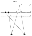
- Fig. 4 is a plan view schematically showing the positional relationship among a monitor surface, a character image, and a reference surface of a 3D image in a case where character signals respectively mixed with right and left image signals are the same signals between which there is binocular parallax;
- Fig. 5 is a block diagram showing the construction of a 3D image display device according to a second embodiment of the present invention; and
- Figs. 6a, 6b and 6c are illustrations for explaining the principle of 3D view by phase shift.
- Referring now to the drawings, a first embodiment of the present invention will be described in detail.
- Fig. 1 illustrates the construction of a 3D image display device according to a first embodiment of the present invention.
- A 2D image signal is inputted to an
input terminal 1. The 2D image signal inputted to theinput terminal 1 is sent to a 2D/3D converting circuit 2. - The 2D/3D converting circuit 2 converts the inputted 2D image signal into a 3D image signal by a method of producing 3D images using field delay, and outputs a left eye image signal L and a right eye image signal R.
- The left eye image signal L produced by the 2D/3D converting circuit 2 is sent to a first
phase adjusting circuit 3a. The right eye image signal R produced by the 2D/3D converting circuit 2 is sent to a secondphase adjusting circuit 3b. - The first
phase adjusting circuit 3a adjusts the horizontal phase of the left eye image signal outputted from the 2D/3D converting circuit 2. The secondphase adjusting circuit 3b adjusts the horizontal phase of the right eye image signal outputted from the 2D/3D converting circuit 2. - The first and second
phase adjusting circuits phase adjusting circuits phase adjusting circuits - An output of the first
phase adjusting circuit 3a is sent to afirst mixing circuit 5a. An output of the secondphase adjusting circuit 3b is sent to asecond mixing circuit 5b. - A character signal generating circuit 4 outputs character signals for displaying a character image on a
display device 6. The character signals outputted from the character signal generating circuit 4 are respectively fed to thefirst mixing circuit 5a and thesecond mixing circuit 5b. - The
first mixing circuit 5a mixes (superposes or inserts) the character signal with the left eye image signal after phase shift processing. Thesecond mixing circuit 5b mixes (superposes or inserts) the character signal with the right eye image signal after phase shift processing. Outputs of thefirst mixing circuit 5a and thesecond mixing circuit 5b are sent to thedisplay device 6. - The
display device 6 displays a 3D image or a 2D image on the basis of the left eye image signal (including the character signal) and the right eye image signal (including the character signal) which are respectively outputted from thefirst mixing circuit 5a and thesecond mixing circuit 5b. - The
display device 6 comprises a signal synthesizing circuit (not shown) for alternately switching and outputting the left eye image signal and the right eye image signal for each field or alternately switching and outputting the left eye image signal and the right eye image signal for each pixel in the horizontal direction. - A
control circuit 7 controls field delay of the 2D/3D converting circuit 2 on the basis of an image for each field of the 2D image signal inputted to theinput terminal 1. Thecontrol circuit 7 controls the amounts of phase shift in the firstphase adjusting circuit 3a and the secondphase adjusting circuit 3b. In addition, thecontrol circuit 7 controls the operation of the character signal generating circuit 4, for example. - An operating unit 8 sets switching of ON/OFF of the 2D/3D converting circuit 2, the first
phase adjusting circuit 3a, the secondphase adjusting circuit 3b, and the character signal generating circuit 4, and sets the amounts of phase shift in the firstphase adjusting circuit 3a and the secondphase adjusting circuit 3b, for example. - Description is made of the operations of the 3D image display device shown in Fig. 1.
- A 2D image signal inputted to the
input terminal 1 is sent to the 2D/3D converting circuit 2. In the 2D/3D converting circuit 2, a left eye image signal L and a right eye image signal R are produced on the basis of the inputted 2D image signal. Specifically, a first image signal used as a basis and a second image signal which is delayed from the first image signal by a predetermined number of fields are produced on the basis of the inputted 2D image signal, and one of the first image signal and the second image signal is produced as a left eye image signal and the other image signal is produced as a right eye image signal. In this example, the first image signal is the 2D image signal itself inputted to the 2D/3D converting circuit 2. - It is determined which of the first image signal and the second image signal is taken as a left eye image signal on the basis of the direction of the horizontal movement of an object in an inputted 2D image. Field delay indicating how many fields are there from a field corresponding to the first image signal to a field corresponding to the second image signal is determined by the amount of the horizontal movement of the object in the inputted 2D image. Such control is carried out by the
control circuit 7. - The left eye image signal L produced by the 2D/3D converting circuit 2 is subjected to horizontal phase shift by a predetermined amount by the first
phase adjusting circuit 3a. On the other hand, the right eye image signal R produced by the 2D/3D converting circuit 2 is subjected to horizontal phase shift by a predetermined amount by the secondphase adjusting circuit 3b. In this case, the direction of the phase shift is so adjusted that a reference surface of a 3D image is positioned behind a monitor surface. Also with respect to an image in which an object hardly horizontally moves, the reference surface of the 3D image is always positioned behind the monitor surface, whereby a viewer experiences a 3D effect. - The
control circuit 7 outputs a character signal for displaying a mark indicating that a 3D image is displayed from the character signal generating circuit 4 upon judgment that the 2D/3D converting circuit 2 is operated. - In the
first mixing circuit 5a, the character signal is mixed with the left eye image signal after phase shift processing. On the other hand, in thesecond mixing circuit 5b, the character signal is mixed with the right eye image signal after phase shift processing. Image signals obtained by thefirst mixing circuit 5a and thesecond mixing circuit 5b are sent to thedisplay device 6. In this example, the character signals respectively outputted to thefirst mixing circuit 5a and thesecond mixing circuit 5b from the character signal generating circuit 4 shall be the same signals between which there is no binocular parallax. - Fig. 2 is a plan view schematically showing the distance from a monitor surface to a reference surface of a 3D image displayed on the
display device 6. Fig. 3 is a perspective view schematically showing the distance from a monitor surface to a reference surface of a 3D image displayed on thedisplay device 6. - As shown in Figs. 2 and 3, a reference surface 9 of a displayed 3D image is positioned behind a
monitor surface 10 by horizontal phase shift in thephase adjusting circuits first mixing circuit 5a and thesecond mixing circuit 5b are the same signals between which there is no binocular parallax, and the character signal is not subjected to phase control, whereby amark 11 represented by the character signal is displayed on the same surface as themonitor surface 10. Consequently, the viewer can recognize the position of themonitor surface 10 by themark 11. - In the 3D image display device according to the first embodiment, the viewer also compares an
object 12 which hardly horizontally moves and is so displayed as to be positioned on the reference surface 9 positioned behind themonitor surface 10 by horizontal phase shift with themark 11, whereby the viewer can easily recognize that theobject 12 is positioned behind themark 11, that is, behind themonitor surface 10 and easily experiences a 3D effect. - Although in the above-mentioned first embodiment, the
phase adjusting circuits monitor surface 10, thephase adjusting circuits monitor surface 10. - The amounts of phase shift in the
phase adjusting circuits - When the
mark 11 is a character, a sign or a figure indicating that a 3D image is displayed on thedisplay device 6, it may be automatically judged which of a 2D image and a 3D image is displayed on thedisplay device 6 on the basis of the image signal inputted to thedisplay device 6, and a character signal may be outputted from the character signal generating circuit 4 only when the 3D image is displayed. As a result, themark 11 is displayed on thedisplay device 6 when the 3D image is displayed on thedisplay device 6, and is not displayed on thedisplay device 6 when the 2D image is displayed on thedisplay device 6. - Furthermore, it may be automatically judged which of a 2D image and a 3D image is displayed on the
display device 6 on the basis of the image signal inputted to thedisplay device 6 to change the type of the character signal depending on the results of the judgment. - As shown in Fig. 4, when the
phase adjusting circuits monitor surface 10, character signals between which there is binocular parallax may be respectively fed to thefirst mixing surface 5a and thesecond mixing circuit 5b so that themark 11 is displayed on asurface 13 ahead of themonitor surface 10. Although in the above-mentioned case, themark 11 is displayed on thesurface 13 ahead of themonitor surface 10, themark 11 may be displayed behind themonitor surface 10. In this case, however, themark 11 must be positioned ahead of the foremost position in 3D view of the 3D image or in approximately the same position as the foremost position in 3D view of the 3D image. On the other hand, when thephase adjusting circuits monitor surface 10, character signals between which there is binocular parallax may be respectively fed to thefirst mixing circuit 5a and thesecond mixing circuit 5b so that themark 11 is displayed ahead of the foremost position in 3D view of the 3D image or in approximately the same position as the foremost position in 3D view of the 3D image. - Fig. 5 illustrates the construction of a 3D image display device according to a second embodiment of the present invention. In Fig. 5, the same reference numerals as those shown in Fig. 1 are assigned the same reference numerals and hence, the description thereof is not repeated.
- In the second embodiment, a 3D image picked up using two cameras, for example, is inputted. That is, a left eye image is picked up using one of the two cameras, and a right eye image is picked up using the other camera.
- A left eye image signal thus obtained is inputted to a left
eye input terminal 1L, and a right eye image signal is inputted to a righteye input terminal 1R. - The left eye image signal inputted to the left
eye input terminal 1L is subjected to horizontal phase shift by a predetermined amount by a firstphase adjusting circuit 3a. On the other hand, the right eye image signal inputted to the righteye input terminal 1R is subjected to horizontal phase shift by a predetermined amount by a secondphase adjusting circuit 3b. Consequently, a reference surface of a 3D image is so adjusted as to be positioned behind a monitor surface. - The left eye image signal whose phase is shifted is fed to a
display device 6 after a character signal from a character signal generating circuit 4 is mixed therewith by afirst mixing circuit 5a. On the other hand, the right eye image signal whose phase is shifted is fed to thedisplay device 6 after the character signal from the character signal generating circuit 4 is mixed therewith by asecond mixing circuit 5b. - In the above-mentioned 3D image display device according to the first or second embodiment, the amounts of phase shift by the
phase adjusting circuits display device 6 and a character image displayed by the character signal. - For example, when a character image in a window frame shape is displayed by a character signal and a 3D image is displayed inside the character image, a viewer can adjust the front and rear positional relationship between the character image in a window frame shape and the 3D image so that the 3D image exists behind the character image by changing the amounts of phase shift in the
phase adjusting circuits - Although the present invention has been described and illustrated in detail, it is clearly understood that the same is by way of illustration and example only and is not to be taken by way of limitation, the spirit and scope of the present invention being limited only by the terms of the appended claims.
Claims (11)
- A three-dimensional image display device comprising:signal converting means for producing from a two-dimensional image signal a left eye image signal and a right eye image signal which constitute a three-dimensional image;first phase adjusting means for controlling the horizontal phase of the left eye image signal produced by said signal converting means;second phase adjusting means for controlling the horizontal phase of the right eye image signal produced by said signal converting means;first mixing means for mixing a character signal with the left eye image signal outputted from said first phase adjusting means;second mixing means for mixing a character signal with the right eye image signal outputted from said second phase adjusting means; anddisplaying means for displaying a composite image comprising said three-dimensional image and said character signal on the basis of outputs of said first mixing means and said second mixing means.
- The three-dimensional image display device according to claim 1, wherein
said signal converting means produces from said two-dimensional image signal a first image signal used as a basis and a second image signal obtained by delaying said first image signal by a predetermined number of fields, and producing one of said first image signal and said second image signal as a left eye image signal and producing the other image signal as a right eye image signal. - The three-dimensional image display device according to claim 1, wherein
said character signal mixed with the left eye image signal by said first mixing means and said character signal mixed with the right eye image signal by said second mixing means are the same signals between which there is no binocular parallax. - The three-dimensional image display device according to claim 2, wherein
said character signal mixed with the left eye image signal by said first mixing means and said character signal mixed with the right eye image signal by said second mixing means are the same signals between which there is no binocular parallax. - The three-dimensional image display device according to claim 1, wherein
said character signal mixed with the left eye image signal by said first mixing means and said character signal mixed with the right eye image signal by said second mixing means are signals between which there is binocular parallax. - The three-dimensional image display device according to claim 2, wherein
said character signal mixed with the left eye image signal by said first mixing means and said character signal mixed with the right eye image signal by said second mixing means are signals between which there is binocular parallax. - The three-dimensional image display device according to claim 1, further comprisingmeans for judging whether the image displayed by said displaying means is a three-dimensional image or a two-dimensional image and determining whether or not said character signals are respectively mixed with the left eye image signal and the right eye image signal on the basis of the results of the judgment.
- The three-dimensional image display device according to claim 1, further comprisingmeans for judging whether the image displayed by said displaying means is a three-dimensional image or a two-dimensional image and changing the type of said character signal on the basis of the results of the judgment.
- A three-dimensional image display device comprising:first phase adjusting means for shifting, out of a left eye image signal and a right eye image signal which constitute a three-dimensional image, the horizontal phase of the left eye image signal;second phase adjusting means for shifting the horizontal phase of said right eye image signal;first mixing means for mixing a character signal with the left eye image signal outputted from said first phase adjusting means;second mixing means for mixing a character signal with the right eye image signal outputted from said second phase adjusting means; anddisplaying means for displaying a composite image comprising said three-dimensional image and said character signal on the basis of outputs of said first mixing means and said second mixing means.
- The three-dimensional image display device according to claim 9, wherein
said character signal mixed with the left eye image signal by said first mixing means and said character signal mixed with the right eye image signal by said second mixing means are the same signals between which there is no binocular parallax. - The three-dimensional image display device according to claim 9, wherein
said character signal mixed with the left eye image signal by said first mixing means and said character signal mixed with the right eye image signal by said second mixing means are signals between which there is binocular parallax.
Applications Claiming Priority (3)
| Application Number | Priority Date | Filing Date | Title |
|---|---|---|---|
| JP7198095 | 1995-03-29 | ||
| JP71980/95 | 1995-03-29 | ||
| JP7198095 | 1995-03-29 |
Publications (3)
| Publication Number | Publication Date |
|---|---|
| EP0735784A2 true EP0735784A2 (en) | 1996-10-02 |
| EP0735784A3 EP0735784A3 (en) | 1997-01-22 |
| EP0735784B1 EP0735784B1 (en) | 2000-05-24 |
Family
ID=13476128
Family Applications (1)
| Application Number | Title | Priority Date | Filing Date |
|---|---|---|---|
| EP96104816A Expired - Lifetime EP0735784B1 (en) | 1995-03-29 | 1996-03-26 | Three-dimensional image display device |
Country Status (4)
| Country | Link |
|---|---|
| US (1) | US5784097A (en) |
| EP (1) | EP0735784B1 (en) |
| KR (1) | KR100375465B1 (en) |
| DE (1) | DE69608491T2 (en) |
Cited By (10)
| Publication number | Priority date | Publication date | Assignee | Title |
|---|---|---|---|---|
| EP0905988A1 (en) * | 1997-09-30 | 1999-03-31 | Kabushiki Kaisha Toshiba | Three-dimensional image display apparatus |
| EP1750458A1 (en) * | 2005-08-02 | 2007-02-07 | Chuan Sheng Chen | 3D TV picture conversion device |
| WO2010010499A1 (en) * | 2008-07-25 | 2010-01-28 | Koninklijke Philips Electronics N.V. | 3d display handling of subtitles |
| EP2293585A1 (en) * | 2009-07-23 | 2011-03-09 | Sony Corporation | Receiving device, communication system, method of combining caption with stereoscopic image, program and data structure |
| WO2011030234A1 (en) * | 2009-09-08 | 2011-03-17 | Nds Limited | Recommended depth value for overlaying a graphics object on three-dimensional video |
| CN102075773A (en) * | 2010-11-25 | 2011-05-25 | 深圳市创凯电子有限公司 | Synchronized method for imaging stereo and planar image mixed signal on super large screen |
| WO2011087470A1 (en) * | 2010-01-13 | 2011-07-21 | Thomson Licensing | System and method for combining 3d text with 3d content |
| EP2401870A2 (en) * | 2009-02-27 | 2012-01-04 | Deluxe Laboratories, Inc. | Systems, apparatus and methods for subtitling for stereoscopic content |
| EP2484120A2 (en) * | 2009-11-06 | 2012-08-08 | Sony Corporation Of America | Stereoscopic overlay offset creation and editing |
| EP2757787A1 (en) * | 2010-08-19 | 2014-07-23 | Samsung Electronics Co., Ltd. | Display apparatus and method for applying on screen display (OSD) thereto |
Families Citing this family (16)
| Publication number | Priority date | Publication date | Assignee | Title |
|---|---|---|---|---|
| KR20010109814A (en) * | 2000-06-02 | 2001-12-12 | 윤병이 | Display apparatus for management 3-dimensional image |
| WO2003005303A2 (en) * | 2001-07-02 | 2003-01-16 | Matchlight Software, Inc. | System and method for discovering and categorizing attributes of a digital image |
| US9063633B2 (en) * | 2006-03-30 | 2015-06-23 | Arjuna Indraeswaran Rajasingham | Virtual navigation system for virtual and real spaces |
| JP4630149B2 (en) * | 2005-07-26 | 2011-02-09 | シャープ株式会社 | Image processing device |
| KR101252686B1 (en) * | 2006-01-23 | 2013-04-10 | (주)쓰리디아이에스 | Driving Apparatus of 2D/3D Image Display Apparatus |
| EP2140688B1 (en) * | 2007-03-16 | 2010-06-23 | Thomson Licensing | System and method for combining text with three-dimensional content |
| RU2512135C2 (en) * | 2008-11-18 | 2014-04-10 | Панасоник Корпорэйшн | Reproduction device, reproduction method and programme for stereoscopic reproduction |
| US8335425B2 (en) * | 2008-11-18 | 2012-12-18 | Panasonic Corporation | Playback apparatus, playback method, and program for performing stereoscopic playback |
| JP2011216964A (en) * | 2010-03-31 | 2011-10-27 | Sony Corp | Display control unit, display control method and program |
| KR101660910B1 (en) * | 2010-04-28 | 2016-09-29 | 주식회사 알티캐스트 | Apparatus and method for processing image data |
| JP5786315B2 (en) * | 2010-11-24 | 2015-09-30 | セイコーエプソン株式会社 | Display device, display device control method, and program |
| JP4989760B2 (en) | 2010-12-21 | 2012-08-01 | 株式会社東芝 | Transmitting apparatus, receiving apparatus, and transmission system |
| EP2706748A4 (en) | 2011-05-06 | 2014-10-01 | Fujitsu Ltd | Stereoscopic image generation device, stereoscopic image generation method, stereoscopic image generation program |
| JP5746908B2 (en) * | 2011-05-06 | 2015-07-08 | 株式会社東芝 | Medical image processing device |
| EP3116227A4 (en) * | 2014-05-08 | 2017-08-16 | Olympus Corporation | Video processor and method for operating video processor |
| WO2018056086A1 (en) * | 2016-09-23 | 2018-03-29 | 日本電信電話株式会社 | Image generating device, image generating method, data structure, and program |
Citations (7)
| Publication number | Priority date | Publication date | Assignee | Title |
|---|---|---|---|---|
| EP0285315A2 (en) * | 1987-04-02 | 1988-10-05 | Tektronix, Inc. | Cursor for use in 3-D imaging systems |
| US4851901A (en) * | 1986-09-03 | 1989-07-25 | Kabushiki Kaisha Toshiba | Stereoscopic television apparatus |
| FR2654291A1 (en) * | 1989-11-03 | 1991-05-10 | Pochet Roger | Method of time-based creation of pairs of stereoscopic images, and device implementing such a method |
| EP0524462A2 (en) * | 1991-07-22 | 1993-01-27 | International Business Machines Corporation | A point addressable cursor for stereo raster display |
| JPH07226959A (en) * | 1994-02-14 | 1995-08-22 | Sharp Corp | Stereoscopic video image display system |
| JPH07274216A (en) * | 1994-03-30 | 1995-10-20 | Sanyo Electric Co Ltd | Stereoscopic video image display device |
| JPH0830806A (en) * | 1994-07-14 | 1996-02-02 | Sanyo Electric Co Ltd | Three-dimensional image conversion method |
Family Cites Families (3)
| Publication number | Priority date | Publication date | Assignee | Title |
|---|---|---|---|---|
| US5175616A (en) * | 1989-08-04 | 1992-12-29 | Her Majesty The Queen In Right Of Canada, As Represented By The Minister Of National Defence Of Canada | Stereoscopic video-graphic coordinate specification system |
| US5428386A (en) * | 1992-08-24 | 1995-06-27 | Envision Medical Corporation | Remote 3D video camera system |
| US5510832A (en) * | 1993-12-01 | 1996-04-23 | Medi-Vision Technologies, Inc. | Synthesized stereoscopic imaging system and method |
-
1996
- 1996-03-25 US US08/622,298 patent/US5784097A/en not_active Expired - Lifetime
- 1996-03-26 EP EP96104816A patent/EP0735784B1/en not_active Expired - Lifetime
- 1996-03-26 DE DE69608491T patent/DE69608491T2/en not_active Expired - Fee Related
- 1996-03-28 KR KR1019960008815A patent/KR100375465B1/en not_active IP Right Cessation
Patent Citations (7)
| Publication number | Priority date | Publication date | Assignee | Title |
|---|---|---|---|---|
| US4851901A (en) * | 1986-09-03 | 1989-07-25 | Kabushiki Kaisha Toshiba | Stereoscopic television apparatus |
| EP0285315A2 (en) * | 1987-04-02 | 1988-10-05 | Tektronix, Inc. | Cursor for use in 3-D imaging systems |
| FR2654291A1 (en) * | 1989-11-03 | 1991-05-10 | Pochet Roger | Method of time-based creation of pairs of stereoscopic images, and device implementing such a method |
| EP0524462A2 (en) * | 1991-07-22 | 1993-01-27 | International Business Machines Corporation | A point addressable cursor for stereo raster display |
| JPH07226959A (en) * | 1994-02-14 | 1995-08-22 | Sharp Corp | Stereoscopic video image display system |
| JPH07274216A (en) * | 1994-03-30 | 1995-10-20 | Sanyo Electric Co Ltd | Stereoscopic video image display device |
| JPH0830806A (en) * | 1994-07-14 | 1996-02-02 | Sanyo Electric Co Ltd | Three-dimensional image conversion method |
Non-Patent Citations (3)
| Title |
|---|
| PATENT ABSTRACTS OF JAPAN vol. 95, no. 008 & JP-A-07 226959 (SHARP CORP), 22 August 1995, * |
| PATENT ABSTRACTS OF JAPAN vol. 95, no. 010 & JP-A-07 274216 (SANYO ELECTRIC CO LTD), 20 October 1995, * |
| PATENT ABSTRACTS OF JAPAN vol. 96, no. 002 & JP-A-08 030806 (SANYO ELECTRIC CO LTD), 2 February 1996, * |
Cited By (20)
| Publication number | Priority date | Publication date | Assignee | Title |
|---|---|---|---|---|
| US6313866B1 (en) | 1997-09-30 | 2001-11-06 | Kabushiki Kaisha Toshiba | Three-dimensional image display apparatus |
| EP0905988A1 (en) * | 1997-09-30 | 1999-03-31 | Kabushiki Kaisha Toshiba | Three-dimensional image display apparatus |
| EP1750458A1 (en) * | 2005-08-02 | 2007-02-07 | Chuan Sheng Chen | 3D TV picture conversion device |
| WO2010010499A1 (en) * | 2008-07-25 | 2010-01-28 | Koninklijke Philips Electronics N.V. | 3d display handling of subtitles |
| EP3454549A1 (en) * | 2008-07-25 | 2019-03-13 | Koninklijke Philips N.V. | 3d display handling of subtitles |
| US9979902B2 (en) | 2008-07-25 | 2018-05-22 | Koninklijke Philips N.V. | 3D display handling of subtitles including text based and graphics based components |
| US8508582B2 (en) | 2008-07-25 | 2013-08-13 | Koninklijke Philips N.V. | 3D display handling of subtitles |
| US8436918B2 (en) | 2009-02-27 | 2013-05-07 | Deluxe Laboratories, Inc. | Systems, apparatus and methods for subtitling for stereoscopic content |
| EP2401870A2 (en) * | 2009-02-27 | 2012-01-04 | Deluxe Laboratories, Inc. | Systems, apparatus and methods for subtitling for stereoscopic content |
| EP2401870A4 (en) * | 2009-02-27 | 2012-12-26 | Deluxe Lab Inc | Systems, apparatus and methods for subtitling for stereoscopic content |
| EP2293585A1 (en) * | 2009-07-23 | 2011-03-09 | Sony Corporation | Receiving device, communication system, method of combining caption with stereoscopic image, program and data structure |
| WO2011030234A1 (en) * | 2009-09-08 | 2011-03-17 | Nds Limited | Recommended depth value for overlaying a graphics object on three-dimensional video |
| EP2484120A2 (en) * | 2009-11-06 | 2012-08-08 | Sony Corporation Of America | Stereoscopic overlay offset creation and editing |
| EP2484120A4 (en) * | 2009-11-06 | 2013-08-21 | Sony Corp America | Stereoscopic overlay offset creation and editing |
| US9030533B2 (en) | 2009-11-06 | 2015-05-12 | Sony Corporation | Stereoscopic overlay offset creation and editing |
| WO2011087470A1 (en) * | 2010-01-13 | 2011-07-21 | Thomson Licensing | System and method for combining 3d text with 3d content |
| EP2757787A1 (en) * | 2010-08-19 | 2014-07-23 | Samsung Electronics Co., Ltd. | Display apparatus and method for applying on screen display (OSD) thereto |
| EP2421271B1 (en) * | 2010-08-19 | 2016-05-04 | Samsung Electronics Co., Ltd. | Display apparatus and method for applying on screen display (OSD) thereto |
| US9350975B2 (en) | 2010-08-19 | 2016-05-24 | Samsung Electronics Co., Ltd. | Display apparatus and method for applying on-screen display (OSD) thereto |
| CN102075773A (en) * | 2010-11-25 | 2011-05-25 | 深圳市创凯电子有限公司 | Synchronized method for imaging stereo and planar image mixed signal on super large screen |
Also Published As
| Publication number | Publication date |
|---|---|
| US5784097A (en) | 1998-07-21 |
| EP0735784B1 (en) | 2000-05-24 |
| KR100375465B1 (en) | 2003-05-17 |
| EP0735784A3 (en) | 1997-01-22 |
| DE69608491D1 (en) | 2000-06-29 |
| DE69608491T2 (en) | 2001-01-18 |
| KR960036815A (en) | 1996-10-28 |
Similar Documents
| Publication | Publication Date | Title |
|---|---|---|
| EP0735784B1 (en) | Three-dimensional image display device | |
| US6353457B2 (en) | Stereoscopic computer graphics image generating apparatus and stereoscopic TV apparatus | |
| EP2410753B1 (en) | Image-processing method for a display device which outputs three-dimensional content, and display device adopting the method | |
| EP0744872B1 (en) | Stereoscopic image display method and apparatus | |
| US20020122585A1 (en) | Electronic stereoscopic media delivery system | |
| JPH08205196A (en) | Transformation method from two-dimensional image into three-dimensional image | |
| US6553184B1 (en) | Method of converting two dimensional images into three-dimensional images | |
| JPH11164328A (en) | Stereoscopic video image display device | |
| EP0717373B1 (en) | Method of converting two-dimensional images into three-dimensional images in a video game set | |
| JP3096612B2 (en) | Time-division stereoscopic video signal detection method, time-division stereoscopic video signal detection device, and stereoscopic video display device | |
| US9225960B2 (en) | Apparatus and method for attenuating stereoscopic sense of stereoscopic image | |
| KR19990070167A (en) | 3D image realization device for 3D image realization in computer system using Sialti monitor | |
| JPH08331598A (en) | Stereoscopic video display device | |
| KR100239132B1 (en) | 3d parallax drawing system and method | |
| JPH10108220A (en) | Device for converting two-dimensional image into three-dimensional image | |
| JP3128467B2 (en) | How to convert 2D video to 3D video | |
| JP3392627B2 (en) | How to convert 2D video to 3D video | |
| JPH08205203A (en) | Three-dimensional image display method | |
| JP2846843B2 (en) | How to convert 2D video to 3D video | |
| US7154501B2 (en) | Method and apparatus for three-dimensional parallax drawing | |
| JPH11110180A (en) | Method and device for converting two-dimensional image into three-dimensional image | |
| EP1126727A1 (en) | Method and apparatus for generating stereoscopic images | |
| JP2951195B2 (en) | Method for generating 3D image from 2D image | |
| JPH07274211A (en) | Method and device for converting two-dimension image into three-dimension image | |
| JPH08149512A (en) | Method for converting two-dimensional video image into three-dimensional video image |
Legal Events
| Date | Code | Title | Description |
|---|---|---|---|
| PUAI | Public reference made under article 153(3) epc to a published international application that has entered the european phase |
Free format text: ORIGINAL CODE: 0009012 |
|
| AK | Designated contracting states |
Kind code of ref document: A2 Designated state(s): DE FR GB |
|
| PUAL | Search report despatched |
Free format text: ORIGINAL CODE: 0009013 |
|
| AK | Designated contracting states |
Kind code of ref document: A3 Designated state(s): DE FR GB |
|
| 17P | Request for examination filed |
Effective date: 19970227 |
|
| RIN1 | Information on inventor provided before grant (corrected) |
Inventor name: MAENAKA, AKIHIRO Inventor name: OKADA, SEIJI Inventor name: MURATA, HARUHIKO Inventor name: IINUMA, TOSHIYA |
|
| 17Q | First examination report despatched |
Effective date: 19981102 |
|
| GRAG | Despatch of communication of intention to grant |
Free format text: ORIGINAL CODE: EPIDOS AGRA |
|
| GRAG | Despatch of communication of intention to grant |
Free format text: ORIGINAL CODE: EPIDOS AGRA |
|
| GRAH | Despatch of communication of intention to grant a patent |
Free format text: ORIGINAL CODE: EPIDOS IGRA |
|
| GRAH | Despatch of communication of intention to grant a patent |
Free format text: ORIGINAL CODE: EPIDOS IGRA |
|
| GRAA | (expected) grant |
Free format text: ORIGINAL CODE: 0009210 |
|
| AK | Designated contracting states |
Kind code of ref document: B1 Designated state(s): DE FR GB |
|
| REF | Corresponds to: |
Ref document number: 69608491 Country of ref document: DE Date of ref document: 20000629 |
|
| ET | Fr: translation filed | ||
| PLBE | No opposition filed within time limit |
Free format text: ORIGINAL CODE: 0009261 |
|
| STAA | Information on the status of an ep patent application or granted ep patent |
Free format text: STATUS: NO OPPOSITION FILED WITHIN TIME LIMIT |
|
| 26N | No opposition filed | ||
| REG | Reference to a national code |
Ref country code: GB Ref legal event code: IF02 |
|
| PGFP | Annual fee paid to national office [announced via postgrant information from national office to epo] |
Ref country code: GB Payment date: 20080326 Year of fee payment: 13 |
|
| PGFP | Annual fee paid to national office [announced via postgrant information from national office to epo] |
Ref country code: FR Payment date: 20080311 Year of fee payment: 13 Ref country code: DE Payment date: 20080407 Year of fee payment: 13 |
|
| GBPC | Gb: european patent ceased through non-payment of renewal fee |
Effective date: 20090326 |
|
| REG | Reference to a national code |
Ref country code: FR Ref legal event code: ST Effective date: 20091130 |
|
| PG25 | Lapsed in a contracting state [announced via postgrant information from national office to epo] |
Ref country code: DE Free format text: LAPSE BECAUSE OF NON-PAYMENT OF DUE FEES Effective date: 20091001 |
|
| PG25 | Lapsed in a contracting state [announced via postgrant information from national office to epo] |
Ref country code: GB Free format text: LAPSE BECAUSE OF NON-PAYMENT OF DUE FEES Effective date: 20090326 Ref country code: FR Free format text: LAPSE BECAUSE OF NON-PAYMENT OF DUE FEES Effective date: 20091123 |