EP0735190B1 - Process for screwing and unscrewing the sleeper screws of a railway track and apparatus for performing the process - Google Patents
Process for screwing and unscrewing the sleeper screws of a railway track and apparatus for performing the process Download PDFInfo
- Publication number
- EP0735190B1 EP0735190B1 EP95810200A EP95810200A EP0735190B1 EP 0735190 B1 EP0735190 B1 EP 0735190B1 EP 95810200 A EP95810200 A EP 95810200A EP 95810200 A EP95810200 A EP 95810200A EP 0735190 B1 EP0735190 B1 EP 0735190B1
- Authority
- EP
- European Patent Office
- Prior art keywords
- tie
- tie screw
- head
- respect
- screw
- Prior art date
- Legal status (The legal status is an assumption and is not a legal conclusion. Google has not performed a legal analysis and makes no representation as to the accuracy of the status listed.)
- Expired - Lifetime
Links
Images


Classifications
-
- E—FIXED CONSTRUCTIONS
- E01—CONSTRUCTION OF ROADS, RAILWAYS, OR BRIDGES
- E01B—PERMANENT WAY; PERMANENT-WAY TOOLS; MACHINES FOR MAKING RAILWAYS OF ALL KINDS
- E01B29/00—Laying, rebuilding, or taking-up tracks; Tools or machines therefor
- E01B29/24—Fixing or removing detachable fastening means or accessories thereof; Pre-assembling track components by detachable fastening means
- E01B29/28—Fixing or removing detachable fastening means or accessories thereof; Pre-assembling track components by detachable fastening means the fastening means being of screw-and-nut type; Apparatus therefor, adapted to additionally drilling holes
Definitions
- the present invention relates to a method of screwing and unscrewing the lag bolts of a railroad track according to which a carriage advancing on the track and carrying lag bolt detection devices and threading heads is used, as well as a machine for setting of the process.
- FR-A-2 682 135 and FR-A-2 666 358 have proposed machines operated by a single operator.
- the machines described in these documents have two double drawing heads to act simultaneously on the four bolts of a cross member, a double head acting by rail file.
- document FR-A-2 682 135 the four heads are lowered simultaneously, after their positioning relative to the four lag bolts, the detection of the nuts being carried out by mechanical feelers.
- Document FR-A-2 666 358 provides for the individual descent of each of the heads and also the possibility that a beam supporting the double heads can pivot relative to an axis perpendicular to the plane of the track to be placed parallel to an oblique cross. There is no provision for prior detection of the nuts other than that made visually by the operator.
- the installation of the dowel heads and the initiation of operations are carried out by an operator behind the two double dowel heads.
- Document FR-A 2 072 853 presents a machine for carrying out railway work.
- a process for screwing and unscrewing lag screws of a railroad is implemented by this machine which comprises a vehicle advancing on the track and supporting threading heads and bolt detection devices.
- the object of the present invention is to propose a method and a machine making it possible to remedy the drawbacks of the prior art and to ensure high quality work at a high rate.
- the different measured positions are recorded progressively to allow an improvement in the working rate of the carriage. So, it is not necessary to wait for the end of a work cycle to measure the positions of the lag screws which will be treated later.
- the invention also relates to a machine for implementing the method according to the invention.
- the machine comprises a carriage provided with means for moving on the track, means for detecting and determining the relative position of a lag screw with respect to a drawing head, of a module per line of rails equipped with at least one dowel head, said module being arranged to be able to be moved relative to the carriage in the direction of the axis of the rail queue, said dowel head being provided with means to be moved relative to the module in a first direction parallel to the axis of the rail line, in a second direction perpendicular to this axis and parallel to the cross-member, in a third direction perpendicular to the plane defined by the two previous directions, and angularly with respect to this third direction, and automatic means individually initiating a drawing cycle for each head.
- the depositor obtained a rate of 400 meters per hour.
- Figure 1 is a schematic side view of the carriage.
- Figure 2 is a partial cross-sectional view of a rail on a cross member.
- Figure 3 is a plan view of a rail on sleepers.
- FIG. 4 is a side view of a carriage more detailed than FIG. 1.
- Figure 5 is a cross-sectional view showing a double dowel head in the working position.
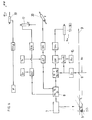
- Figure 6 is a block diagram of a device for controlling the positioning of each dowel head.
- the carriage 1 shown in Figure 1 is provided with a drawbar 2 by which it is connected to a machine ensuring locomotion of the carriage.
- the carriage moves on the rail 3 fixed to the crosspieces 4 by means of lag screws 5, 26.
- the carriage 1 could be provided with autonomous displacement means.
- the carriage 1 is provided with a group 6 ensuring the supply of energy, both hydraulic and electric.
- An optoelectronic device 7 for detecting and measuring the position of the lag bolts is arranged on the front part of the carriage. In principle, such a device per line of rails is used.
- the device 7 is connected to a box 8 for storing and processing all the electronic data.
- An encoder 9 disposed at the rear end of the carriage gives the position X 0 of the carriage at all times on the rail 3.
- the carriage 1 is provided on its upper part with a horizontal rod 11 secured to the carriage 1 on which a module slides 10 provided on its lower part with two rollers 12 ensuring its guiding with respect to the rail 3.
- the module 10 is moved along an axis X parallel to the axis of the rail by a jack 13 controlled by a servovalve 14.
- the position X M of the module 10 with respect to the carriage 1 is indicated by a linear potentiometer 15.
- the module 10 carries two drawing heads 16, 16a of which only one is visible in FIG. 1. Each head is provided with a jack 17 actuated by a valve 18 for raising and lowering the dowel head.
- a linear encoder 19 makes it possible to know the height of the head at any time.
- a double-acting cylinder 20 supplied by a valve 21 ensures the transverse displacement of the head 16 by sliding it on transverse guides 22.
- An encoder 23 makes it possible to measure the transverse displacement of the head (Fig. 3).
- the module is provided at its lower part with two clamps 24 actuated by jacks 25 (Fig. 4).
- the clamps make it possible to immobilize the module relative to the rail 3 so that the head 16 can unscrew the lag screw.
- the device 7 is an optoelectronic device, for example a CCD camera (for Charge Coupling Device) with high resolution.
- a CCD camera for Charge Coupling Device
- Such a camera is, in principle, used for each row of rails. Indeed, the image captured by this camera is divided into two parts, namely one part by lag screw. The position of each lag screw is thus captured in an XY plane (see definition below), which makes it possible to guide each bolt head individually.
- the carriage 1 is also equipped with a module 10 provided with two drawing heads 16 and 16a.
- the head 16a is shown in the high position and it is identical to the head 16. It is mounted on two guide columns 27 secured to a sheath 28 sliding on a guide rod 29.
- a jack 30 controlled by a valve not shown acts on a reference 31 formed by a triangular plate one of the vertices of which is secured to the end of the jack 30, another vertex is secured to a rod 27a secured to one of the guide columns 27 and the third provided with a encoder 32 is articulated around an axis 31a integral with the module 10.
- the heads 16 and 16a are independent of each other concerning the direction of movement along three orthogonal axes X, Y, Z inside of course the module 10.
- a jack 33 (FIG. 5) allows by its extension the inclination of the head by pivoting around the rod guide 29.
- Figure 5 there is shown the drawing head 16 in a position perpendicular to the cross member 4, that is to say corresponding to an angle ⁇ equal to 0 °. This angle could vary up to approximately 5 ° by the sole extension of the jack 33.
- the potentiometer 15 in FIG. 1 enabling the displacement of the module 10 to be known has been replaced in FIG. 4 by a rotary encoder 34 driven by a belt 35, the two ends of which are fixed on two anterior and posterior faces of the module 10, in particular at points 10a and 10b.
- Three return rollers 34a, 34b, 34c ensure the movement of this toothed belt during the movement of the module 10 inside the carriage.
- each drawing head 16 comprises a hydraulic motor 16b with incorporated reduction gear, a counter 16c for the number of revolutions and a key 16d.
- the detector 7 captures and stores the exact position of each lag screw in the XY plane of an orthogonal reference base XYZ defined as follows:
- X is an axis parallel to the axis of the rail 3 and located on the top of the rail
- Y is an axis perpendicular to the previous one and parallel to the cross-member, located on the internal side of the rail, Z being perpendicular to the plane defined by the two other axes.
- the bolt coordinates are the pairs X 1i Y 1i , X 2i Y 2i , X 3i Y 3i , X 4i Y 4i .
- the computer calculates the differences ⁇ X, ⁇ Y between the positions of the lag bolts and those of the corresponding heads along the two axes X and Y.
- the slave jacks 13, 20 and 30 bring each of the heads above the lag screws to be treated, for example the lag screw 26. In other words, the heads move until the differences ⁇ X, ⁇ Y are zero.
- the jack 25 then closes the clamp 24 to immobilize the module 10 and the cycle of each drawing head begins, namely: the descent to the lag screw, the screwing and the ascent. Subsequently the module 10 is released by loosening the clamp 24 and it moves in the direction of the lag bolts of the next crosspiece.
- X i + 1 X 0 (i + 1) + X D etc.
- the value of the angle ⁇ is preset on the basis of visual observations prior to the work or in accordance with the data established during the installation of the track. However, if for one reason or another, one of the lag bolts has been pressed with an angle which differs from the preset angle ⁇ , when the tool 16d tries to grasp the head of the lag bolt, an auto-adjustment of the angle ⁇ is produced around the preset position so that the tool 16d can grasp the lag screw without destroying it.
- a lag screw 5 arranged on a line of rails 3 and whose absolute coordinates are X i , Y i , Z i .
- the device 7 makes it possible to know the coordinates detected X D , Y D , Z D.
- the potentiometer 15 indicates the position longitudinal X M of the carriage, which makes it possible to calculate the absolute position of the carriage X M + X 0 and to calculate the difference ⁇ X i .
- ⁇ X i is the distance that the carriage 1 must travel for the head to be positioned above the lag screw 5 and which corresponds to a signal SV X to be sent to the solenoid valve of the jack 13 and possibly 30 to ensure the movement along X of the module.
- the value Y D is transmitted to a computer which makes it possible to calculate the difference ⁇ Y i taking account of the position Y M of the module which is known since it is always the same. It is thus possible to send a signal SV y corresponding to ⁇ Y i to the solenoid valve of the double-acting cylinder 20 to position the head of the lag screw along the Y axis.
- the position Z D of the module which is also constant makes it possible to calculate the value ⁇ Z i which corresponds to a signal SV Z to be sent to the solenoid valve of the jack 17 allowing the head to be lowered to the height of the lag screw 5. Finally, if necessary , the angle ⁇ is introduced into a device, which makes it possible to send a signal EV ⁇ to the solenoid valve of the piston 33 to control the angular displacement of the drawing head.
Abstract
Description
La présente invention concerne un procédé de vissage et de dévissage des tirefonds d'une voie ferrée selon lequel un chariot avançant sur la voie et portant des dispositifs de détection de tirefonds et des têtes de tirefonnage est utilisé, ainsi qu'une machine pour la mise en oeuvre du procédé.The present invention relates to a method of screwing and unscrewing the lag bolts of a railroad track according to which a carriage advancing on the track and carrying lag bolt detection devices and threading heads is used, as well as a machine for setting of the process.
Lors de la pose ou de la dépose des rails d'une voie ferrée, on utilise le plus souvent des tirefonneuses individuelles légères actionnées chacune par un opérateur. Il faut donc quatre personnes pour visser ou dévisser les quatre tirefonds d'une traverse à une cadence relativement rapide de 200 à 250 mètres à l'heure.When laying or removing the rails of a railway track, light individual screw drivers are most often used, each actuated by an operator. It therefore takes four people to screw or unscrew the four bolts of a sleeper at a relatively rapid rate of 200 to 250 meters per hour.
C'est le seul moyen manuel actuellement connu qui puisse positionner avec précision une tête de tirefonnage sur la tête d'un tirefond. Souvent, celle-ci n'est pas à sa place théorique, soit parce que la traverse n'est pas parallèle aux autres, soit parce que la traverse est dans une courbe, soit parce que la traverse a été mal alignée ou pour toute autre raison. Le tirefond peut également être enfoncé de manière oblique au lieu d'être situé sur un plan perpendiculaire à celui de l'axe de la traverse.It is the only manual means currently known which can accurately position a dowel head on the head of a dowel. Often, this is not in its theoretical place, either because the cross is not parallel to the others, or because the cross is in a curve, or because the cross has been misaligned or for any other right. The lag screw can also be inserted obliquely instead of being located on a plane perpendicular to that of the axis of the crosspiece.
On a proposé, dans les documents FR-A-2 682 135 et FR-A-2 666 358, des machines actionnées par un seul opérateur. Les machines décrites dans ces documents disposent de deux doubles têtes de tirefonnage pour agir simultanément sur les quatre tirefonds d'une traverse, une double tête agissant par file de rail.FR-A-2 682 135 and FR-A-2 666 358 have proposed machines operated by a single operator. The machines described in these documents have two double drawing heads to act simultaneously on the four bolts of a cross member, a double head acting by rail file.
Dans le document FR-A-2 682 135, les quatre têtes sont baissées simultanément, après leur positionnement par rapport aux quatre tirefonds, la détection des écrous étant réalisée par des palpeurs mécaniques. Dans le document FR-A-2 666 358 on a prévu la descente individuelle de chacune des têtes et également la possibilité qu'une poutre supportant les doubles têtes puisse pivoter par rapport à un axe perpendiculaire au plan de la voie pour se mettre parallèlement à une traverse oblique. Il n'est pas prévu de détection préalable des écrous autre que celle faite visuellement par l'opérateur.In document FR-A-2 682 135, the four heads are lowered simultaneously, after their positioning relative to the four lag bolts, the detection of the nuts being carried out by mechanical feelers. Document FR-A-2 666 358 provides for the individual descent of each of the heads and also the possibility that a beam supporting the double heads can pivot relative to an axis perpendicular to the plane of the track to be placed parallel to an oblique cross. There is no provision for prior detection of the nuts other than that made visually by the operator.
La mise en place des têtes de tirefonnage et l'enclenchement des opérations sont réalisés par un opérateur se trouvant derrière les deux doubles têtes de tirefonnage.The installation of the dowel heads and the initiation of operations are carried out by an operator behind the two double dowel heads.
Ces dispositifs permettent, bien entendu, d'améliorer les conditions de travail car au lieu de quatre personnes on emploie une seule personne pour piloter la machine. Néanmoins, le positionnement des têtes de tirefonnage par rapport aux tirefonds se fait, soit par des palpeurs mécaniques rudimentaires, soit visuellement par l'opérateur. Il s'en suit que la précision de positionnement des outils par rapport aux tirefonds et la vitesse d'exécution dépendent surtout de l'habileté et de l'expérience de l'opérateur. Quant aux possibilités de réglage, ne serait-ce que pour les tirefonds inclinés, elles sont limitées, voire absentes.These devices allow, of course, to improve working conditions because instead of four people, one person is employed to control the machine. Nevertheless, the positioning of the drawing heads relative to the lag screws is done either by rudimentary mechanical feelers, or visually by the operator. It follows that the precision of positioning of the tools relative to the lag screws and the speed of execution depend above all on the skill and experience of the operator. As for the adjustment possibilities, if only for the inclined lag bolts, they are limited or even absent.
Le document FR-A 2 072 853 présente une machine pour l'exécution de travaux de voie ferrée. En particulier, un procédé de vissage et de dévissage des tirefonds d'une voie ferrée est mis en oeuvre par cette machine qui comporte un véhicule avançant sur la voie et supportant des têtes de tirefonnage et des dispositifs de détection des tirefonds.Document FR-A 2 072 853 presents a machine for carrying out railway work. In particular, a process for screwing and unscrewing lag screws of a railroad is implemented by this machine which comprises a vehicle advancing on the track and supporting threading heads and bolt detection devices.
La présente invention a pour but de proposer un procédé et une machine permettant de remédier aux inconvénients de la technique antérieure et d'assurer un travail de haute qualité à une cadence élevée.The object of the present invention is to propose a method and a machine making it possible to remedy the drawbacks of the prior art and to ensure high quality work at a high rate.
Le procédé selon l'invention est défini par la clause caractérisante de la revendication 1.The method according to the invention is defined by the characterizing clause of
Les avantages du procédé selon l'invention sont :
- le fait que l'on détermine la position relative exacte des tirefonds par rapport aux moyens de vissage de préférence avec un capteur sans contact permet par la suite de positionner individuellement chaque tête de tirefonnage par rapport au tirefond avec exactitude,
- le fait que l'on peut incliner chaque tête individuellement par rapport au plan de la voie permet de l'adapter à une éventuelle position oblique d'un tirefond,
- le fait que chaque tête est déplaçable et enclenchable individuellement permet de traiter chaque tirefond individuellement, ce qui divise par quatre, voire par huit, le taux de "ratés" et évite que les traverses de béton se fissurent,
- le fait que toutes ces opérations sont réalisées de manière purement automatique sans aucune intervention humaine, par des moyens techniques fiables ne nécessitant pas d'investissement financier déraisonnable, permet des économies de frais de personnel, lequel est libéré de tâches répétitives ingrates, et assure une précision optimale du couple de serrage des tirefonds.
- the fact that the exact relative position of the lag bolts is determined relative to the screwing means, preferably with a contactless sensor, makes it possible thereafter to position each bolt head relative to the lag bolt individually,
- the fact that each head can be tilted individually relative to the plane of the track makes it possible to adapt it to a possible oblique position of a lag screw,
- the fact that each head is movable and snap-on individually makes it possible to treat each lag screw individually, which divides by four, or even by eight, the rate of "misfires" and prevents the concrete sleepers from cracking,
- the fact that all these operations are carried out in a purely automatic manner without any human intervention, by reliable technical means not requiring no unreasonable financial investment, allows savings in personnel costs, which is freed from unrewarding repetitive tasks, and ensures optimum precision of the tightening torque of the lag bolts.
Ainsi donc, non seulement les coûts de main-d'oeuvre sont supprimés, mais les opérations de positionnement des outils par rapport aux tirefonds se font avec précision et rapidement, sans dépendre de l'habileté et de la vitesse d'exécution d'une personne.Thus, not only are the labor costs eliminated, but the tools positioning operations relative to the lag screws are done precisely and quickly, without depending on the skill and speed of execution of a no one.
Selon le procédé, la position relative d'un tirefond par rapport à la tête correspondante de tirefonnage est déterminée selon les étapes suivantes :
- a1. une base de référence orthogonale XYZ est définie, X étant parallèle à l'axe du rail, Y parallèle à la traverse et Z perpendiculaire au plan XY,
- a2. la position du chariot sur la voie est mesurée en permanence par rapport à la base de référence,
- a3. la position relative de chacune des têtes de tirefonnage est mesurée en permanence par rapport au chariot,
- a4. la position de chaque tirefond est détectée et calculée par rapport à la base de référence et,
- a5. l'écart de chaque tirefond par rapport à la tête de tirefonnage est calculé.
- a1. an orthogonal reference base XYZ is defined, X being parallel to the axis of the rail, Y parallel to the cross-member and Z perpendicular to the plane XY,
- a2. the position of the carriage on the track is continuously measured relative to the reference base,
- a3. the relative position of each of the dowel heads is continuously measured with respect to the carriage,
- a4. the position of each lag screw is detected and calculated relative to the reference base and,
- at 5. the distance of each lag screw from the thread head is calculated.
De préférence, les différentes positions mesurées sont enregistrées au fur et à mesure pour permettre une amélioration de la cadence de travail du chariot. Ainsi, il n'est pas nécessaire d'attendre la fin d'un cycle de travail pour mesurer les positions des tirefonds qui seront traités par la suite.Preferably, the different measured positions are recorded progressively to allow an improvement in the working rate of the carriage. So, it is not necessary to wait for the end of a work cycle to measure the positions of the lag screws which will be treated later.
Selon un mode de réalisation particulier du procédé, le cycle de tirefonnage pour le vissage comporte les étapes suivantes après positionnement d'une tête de tirefonnage par rapport au tirefond :
- a. blocage longitudinal de la tête sur le rail correspondant,
- b. descente rapide vers le tirefond,
- c. introduction de l'outil saisissant la tête du tirefond,
- d. mise en rotation de l'outil,
- e. mesure du couple de serrage,
- f. arrêt automatique lorsqu'une valeur prédéterminée de couple de serrage est dépassée,
- g. dégagement de l'outil et remontée rapide, et
- h. déblocage de la tête du rail correspondant.
- at. longitudinal locking of the head on the corresponding rail,
- b. rapid descent to the lag screw,
- vs. introduction of the tool gripping the head of the lag screw,
- d. tool rotation,
- e. measurement of the tightening torque,
- f. automatic stop when a predetermined tightening torque value is exceeded,
- g. quick release of the tool, and
- h. release of the head of the corresponding rail.
L'invention concerne également une machine pour la mise en oeuvre du procédé selon l'invention.The invention also relates to a machine for implementing the method according to the invention.
La machine comprend un chariot muni de moyens pour se déplacer sur la voie, des moyens pour détecter et déterminer la position relative d'un tirefond par rapport à une tête de tirefonnage, d'un module par file de rails équipé d'au moins une tête de tirefonnage, ledit module étant agencé pour pouvoir être déplacé par rapport au chariot dans la direction de l'axe de la file de rail, ladite tête de tirefonnage étant munie de moyens pour être déplacée par rapport au module selon une première direction parallèlement à l'axe de la file de rails, selon une deuxième direction perpendiculairement à cet axe et parallèlement à la traverse, selon une troisième direction perpendiculairement au plan défini par les deux directions précédentes, et angulairement par rapport à cette troisième direction, et des moyens automatiques enclenchant individuellement un cycle de tirefonnage pour chaque tête.The machine comprises a carriage provided with means for moving on the track, means for detecting and determining the relative position of a lag screw with respect to a drawing head, of a module per line of rails equipped with at least one dowel head, said module being arranged to be able to be moved relative to the carriage in the direction of the axis of the rail queue, said dowel head being provided with means to be moved relative to the module in a first direction parallel to the axis of the rail line, in a second direction perpendicular to this axis and parallel to the cross-member, in a third direction perpendicular to the plane defined by the two previous directions, and angularly with respect to this third direction, and automatic means individually initiating a drawing cycle for each head.
Avec le procédé selon l'invention et la machine de mise en oeuvre, le déposant a obtenu une cadence de 400 mètres à l'heure.With the method according to the invention and the implementation machine, the depositor obtained a rate of 400 meters per hour.
L'invention sera décrite plus en détail à l'aide du dessin annexé.The invention will be described in more detail using the attached drawing.
La figure 1 est une vue schématique de côté du chariot.Figure 1 is a schematic side view of the carriage.
La figure 2 est une vue en coupe transversale partielle d'un rail sur une traverse.Figure 2 is a partial cross-sectional view of a rail on a cross member.
La figure 3 est une vue en plan d'un rail sur des traverses.Figure 3 is a plan view of a rail on sleepers.
La figure 4 est une vue de côté d'un chariot plus détaillé que la figure 1.FIG. 4 is a side view of a carriage more detailed than FIG. 1.
La figure 5 est une vue en coupe transversale montrant une double tête de tirefonnage en position de travail.Figure 5 is a cross-sectional view showing a double dowel head in the working position.
La figure 6 est un schéma bloc d'un dispositif permettant de commander le positionnement de chaque tête de tirefonnage.Figure 6 is a block diagram of a device for controlling the positioning of each dowel head.
Le chariot 1 présenté à la figure 1 est muni d'un timon 2 par lequel il est relié à une machine assurant la locomotion du chariot. Le chariot se déplace sur le rail 3 fixé aux traverses 4 au moyen de tirefonds 5, 26. Le chariot 1 pourrait être muni de moyens de déplacement autonomes.The
Le chariot 1 est muni d'un groupe 6 assurant l'alimentation en énergie aussi bien hydraulique qu'électrique. Un dispositif optoélectronique 7 de détection et de mesure de la position des tirefonds est disposé sur la partie antérieure du chariot. En principe, un tel dispositif par file de rails est utilisé. Le dispositif 7 est relié à un coffret 8 de mémorisation et de traitement de toutes les données électroniques. Un codeur 9 disposé à l'extrémité postérieure du chariot donne à chaque instant la position X0 du chariot sur le rail 3. Le chariot 1 est muni sur sa partie supérieure d'une tige horizontale 11 solidaire du chariot 1 sur laquelle coulisse un module 10 muni sur sa partie inférieure de deux galets 12 assurant son guidage par rapport au rail 3. Le module 10 est déplacé selon un axe X parallèle à l'axe du rail par un vérin 13 commandé par une servovalve 14. La position XM du module 10 par rapport au chariot 1 est indiquée par un potentiomètre linéaire 15. Le module 10 porte deux têtes de tirefonnage 16, 16a dont une seule est visible sur la figure 1. Chaque tête est munie d'un vérin 17 actionné par une valve 18 pour la montée et la descente de la tête de tirefonnage. Un codeur linéaire 19 permet de connaître la hauteur de la tête à tout moment. Un vérin à double effet 20 alimenté par une valve 21 assure le déplacement transversal de la tête 16 en la faisant coulisser sur des guides transversaux 22. Un codeur 23 permet de mesurer le déplacement transversal de la tête (Fig. 3).The
Pour permettre l'immobilisation du module 10 par rapport au rail 3, le module est muni à sa partie inférieure de deux pinces 24 actionnées par des vérins 25 (Fig. 4). Ainsi, lorsque la tête de tirefonnage 16 se trouve au-dessus d'un tirefond 26 détecté et localisé préalablement par le dispositif 7, les pinces permettent d'immobiliser le module par rapport au rail 3 afin que la tête 16 puisse dévisser le tirefond.To allow the immobilization of
Le dispositif 7 est un dispositif optoélectronique, par exemple une caméra CCD (pour Charge Coupling Device) à haute résolution. Une telle caméra est, en principe, utilisée pour chaque file de rails. En effet, l'image captée par cette caméra est partagée en deux parties, à savoir une partie par tirefond. La position de chaque tirefond est ainsi captée dans un plan XY (voir définition plus loin), ce qui permet de guider chaque tête de tirefonnage individuellement.The
L'exécution représentée à la figure 4 est plus détaillée. Le chariot 1 est également équipé d'un module 10 muni de deux têtes de tirefonnage 16 et 16a. La tête 16a est représentée en position haute et elle est identique à la tête 16. Elle est montée sur deux colonnes de guidage 27 solidaires d'un fourreau 28 coulissant sur une tige de guidage 29. Un vérin 30 commandé par une valve non représentée agit sur un renvoi 31 formé d'une plaque triangulaire dont un des sommets est solidaire de l'extrémité du vérin 30, un autre sommet est solidaire d'une tige 27a solidaire d'une des colonnes de guidage 27 et le troisième muni d'un codeur 32 est articulé autour d'un axe 31a solidaire du module 10.The execution shown in Figure 4 is more detailed. The
Les têtes 16 et 16a sont indépendantes l'une de l'autre concernant le sens de déplacement selon trois axes orthogonaux X, Y, Z à l'intérieur bien entendu du module 10.The
Afin de permettre l'inclinaison de la tête 16 d'un angle ϕ pour serrer ou desserrer des tirefonds obliques par rapport aux traverses, un vérin 33 (figure 5) permet par son extension l'inclinaison de la tête par pivotement autour de la tige de guidage 29. A la figure 5 on a représenté la tête de tirefonnage 16 en position perpendiculaire à la traverse 4, c'est-à-dire correspondant à un angle ϕ égal à 0°. Cet angle pourrait varier jusqu'à environ 5° par la seule extension du vérin 33.In order to allow the inclination of the
Le potentiomètre 15 de la figure 1 permettant de connaître le déplacement du module 10 a été remplacé à la figure 4 par un codeur rotatif 34 entraîné par une courroie 35 dont les deux extrémités sont fixées sur deux faces antérieures et postérieures du module 10, notamment aux points 10a et 10b. Trois galets de renvoi 34a, 34b, 34c assurent le déplacement de cette courroie crantée lors du déplacement du module 10 à l'intérieur du chariot.The
A la figure 4, le module 10 est suspendu à un tube 11 par deux paires de galets 36, 37, 38, 39 qui assurent la suspension et le guidage du module 10, son déplacement étant fourni par le vérin 13. Chaque tête de tirefonnage 16 comprend un moteur hydraulique 16b avec réducteur incorporé, un compteur 16c du nombre de tours et une clé 16d.In FIG. 4, the
A partir de cette machine, on décrira maintenant le procédé selon l'invention.From this machine, the method according to the invention will now be described.
Lors de l'avance du chariot 1 sur le rail 3, le détecteur 7 capte et mémorise la position exacte de chaque tirefond dans le plan XY d'une base de référence orthogonale XYZ définie de la manière suivante : X est un axe parallèle à l'axe du rail 3 et situé sur le sommet du rail, Y est un axe perpendiculaire au précédent et parallèle à la traverse, situé sur le flanc interne du rail, Z étant perpendiculaire au plan défini par les deux autres axes.When the
Ainsi, pour une traverse i, les coordonées de tirefonds sont les couples X1i Y1i, X2i Y2i, X3i Y3i, X4i Y4i. L'ordinateur calcule ensuite les différences ΔX, ΔY entre les positions de tirefonds et celles des têtes correspondantes selon les deux axes X et Y.Thus, for a cross member i, the bolt coordinates are the pairs X 1i Y 1i , X 2i Y 2i , X 3i Y 3i , X 4i Y 4i . The computer then calculates the differences ΔX, ΔY between the positions of the lag bolts and those of the corresponding heads along the two axes X and Y.
Les vérins asservis 13, 20 et 30 amènent chacune des têtes au-dessus des tirefonds à traiter, par exemple le tirefond 26. En d'autres termes, les têtes se déplacent jusqu'à ce que les différences ΔX, ΔY soient nulles. Le vérin 25 ferme alors la pince 24 pour immobiliser le module 10 et le cycle de chaque tête de tirefonnage commence, à savoir : la descente vers le tirefond, le vissage et la remontée. Par la suite le module 10 est libéré par desserrage de la pince 24 et il se déplace en direction des tirefonds de la traverse suivante.The slave jacks 13, 20 and 30 bring each of the heads above the lag screws to be treated, for example the
En se référant maintenant à la figure 1, on pourrait représenter plus en détail le calcul des différences ΔX, ΔY. En effet, la position du chariot 1 et notamment celle de sa partie postérieure (dans le sens de déplacement pendant le travail) est X0 ; la distance entre cette partie postérieure du chariot et la position du détecteur étant XD, la position absolue des tirefonds d'une traverse détectée par le détecteur 7 sera Xi = X0i + XD, X0i étant la position de référence du chariot pour la traverse i. De la même manière pour le tirefond qui se trouve à la position i + 1, on aura X i + 1 = X0 (i + 1) + XD etc. La position du module sur le chariot étant XM, ainsi la distance à parcourir par une tête de tirefonnage pour arriver à la position Xi est égale à ΔXi = Xi - (XM + X0M), X0M étant la position du chariot à l'instant du calcul. Un système hydraulique recevant les valeurs de calcul permet le déplacement des têtes à travers des valves hydrauliques alimentant des pistons de commande (voir fig. 6).Referring now to FIG. 1, the calculation of the differences ΔX, ΔY could be represented in more detail. Indeed, the position of the
Les déplacements selon Y et Z sont plus simples puisqu'il suffit de connaître les positions Yi et Zi des tirefonds et YM et ZM du module et de faire annuler la différence Yi-YM et Zi-ZM lorsque ΔXi = 0.The displacements along Y and Z are simpler since it suffices to know the positions Y i and Z i of the lag bolts and Y M and Z M of the module and to cancel the difference Y i -Y M and Z i -Z M when ΔX i = 0.
La valeur de l'angle ϕ est préréglée sur la base de constatations visuelles préalables aux travaux ou conformément aux données établies lors de la mise en place de la voie. Néanmoins, si pour une raison ou pour une autre, l'un des tirefonds a été enfoncé avec un angle qui diffère de l'angle ϕ préréglé, lorsque l'outil 16d essaie de saisir la tête du tirefond, un autoréglage de l'angle ϕ est réalisé autour de la position préréglée afin que l'outil 16d puisse saisir le tirefond sans le détruire.The value of the angle ϕ is preset on the basis of visual observations prior to the work or in accordance with the data established during the installation of the track. However, if for one reason or another, one of the lag bolts has been pressed with an angle which differs from the preset angle ϕ, when the
Sur le schéma bloc de la figure 6, nous avons représenté un tirefond 5 disposé sur une file de rails 3 et dont les coordonnées absolues sont Xi, Yi, Zi. Le dispositif 7 permet de connaître les coordonnées détectées XD, YD , ZD . Le codeur 9 indique la position X0 du chariot 1 ce qui permet, dans un premier temps, de calculer la coordonnée absolue Xi = XD + X0 du tirefonds. Par la suite, le potentiomètre 15 indique la position longitudinale XM du chariot, ce qui permet de calculer la position absolue du chariot XM + X0 et de calculer la différence ΔXi. ΔXi est la distance que doit parcourir le chariot 1 pour que la tête soit positionnée au-dessus du tirefond 5 et qui correspond à un signal SVX à envoyer à l'électrovalve du vérin 13 et éventuellement 30 pour assurer le déplacement selon X du module. De la même manière, la valeur YD est transmise à un calculateur qui permet de calculer la différence ΔYi en tenant compte de la position YM du module qui est connue puisqu'elle est toujours la même. On peut ainsi envoyer un signal SVy correspondant à ΔYi à l'électrovalve du vérin à double effet 20 pour positionner la tête de tirefonds selon l'axe Y.In the block diagram of FIG. 6, we have shown a
La position ZD du module qui est également constante permet de calculer la valeur ΔZi qui correspond à un signal SVZ à envoyer à l'électrovalve du vérin 17 permettant de baisser la tête à la hauteur du tirefond 5. Enfin, le cas échéant, l'angle ϕ est introduit dans un dispositif, ce qui permet d'envoyer un signal EVϕ à l'électrovalve du piston 33 pour commander le déplacement angulaire de la tête de tirefonnage.The position Z D of the module which is also constant makes it possible to calculate the value ΔZ i which corresponds to a signal SV Z to be sent to the solenoid valve of the
Claims (12)
- Process for screwing and unscrewing tie screws of a railroad according to which a vehicle (1) advancing on the railroad and carrying tie screw tightening heads (16,16a) and tie screw (7,8) detection devices is used, the vehicle (1) being displaced continuously whereas the tie screw tightening heads are displaced with respect to said vehicle by jumps from one work position to the other characterised in that the inclination of each tie screw tightening head (16, 16a), where necessary, is adjusted and in that the following steps are realised in a totally automatic manner for each tie:a. the relative position of each tie screw with respect to the corresponding tie screw head is determined according to the following steps:a1. an orthogonal reference base XYZ is defined, X being parallel to the rail axis, Y perpendicular to the previous and parallel to the tie and Z being perpendicular to the XY plane,a2. the relative position of the vehicle on the track is continually measured with respect to the reference base,a3. the relative position of each tie screw head is continually measured with respect to the vehicle,a4. the position of each tie screw is detected and calculated with respect to the reference base and,a5. the deviation in position between each tie screw and the tie screw head is calculated;b. each tie screw head is positioned in the XY plane in order to coincide with the exact position of a tie screw;c. a tie screw fastening cycle is individually started for each tie screw head comprising lowering, screwing, respectively unscrewing of the tie screws and raising.
- Process according to claim 1, characterised by the fact that when the calculated deviations in position are equal to zero, the tie screw fastening cycle of the tie screw fastening head starts automatically.
- Process according to one of claims 1 or 2, characterised by the fact that the values measured at steps a2, a3 and a4 are stored in a computer (8).
- Process according to one or claims 1 to 3, characterised in that the automatic tie screw fastening cycle for screwing comprises the following steps, after the positioning of a tie screw fastening head with respect to the tie screw:a. longitudinal locking of the head on the corresponding rail,b. quick lowering toward the tie screw,c. introduction of the tool grasping the tie screw head,d. rotation of the tool,e. measurement of the screwing torque,f. automatic stop when a predetermined value of screwing torque is exceeded,g. release of the tool and quick raise,h. unlocking of the tie screw head from the corresponding rail.
- Machine for carrying out the process according to one of claims 1 to 4, comprising a vehicle (1) provided with means enabling said vehicle to move along the track, means (7,8) for detecting et determining the relative position of a tie screw (26) with respect to a tie screw head (16, 16a), a module (10) for each rail track (3), equipped with at least one tie screw head (16, 16a), said module (10) being designed so as to be movable with respect to the vehicle (1) in the direction of the axis of the rail track (3), said tie screw head (16,16a) being provided with means (30,31,27a;17,18;20,21,22;33) for being moved with respect to the module in a first direction parallel to the axis of the rail track (3), in a second direction perpendicularly to said axis and parallel to the tie (4), in a third direction perpendicular to the plane defined by both preceding directions, and angularly with respect to said third direction, and means automatically engaging an individual tie screw fastening cycle for each head (16,16a).
- Machine according to claim 5, characterised by the fact that it is additionally provided with means (9;7,8;15) for detecting and measuring the position of the vehicle (1) on the track, the position of the tie screw (26) and the position of the corresponding tie screw heads (16,16a) with respect to the vehicle (1) and calculating means for calculating the relative position of the tie screw heads (16,16a) with respect to the corresponding tie screws (26) and for permanently calculating the deviation between said heads and the next screw heads.
- Machine according to one of claims 5 or 6, characterised by the fact that the automatic means engage a tie crew fastening cycle when the calculated deviations equal zero.
- Machine according to one of claims 6 or 7, characterised by the fact that it is provided with means (8) allowing to record the position values of the vehicle (1), of the tie screw (26) and of the corresponding tie screw heads (16,16a).
- Machine according to one of claims 5 to 8, characterised by the fact that the vehicle (1) is provided with automotive means.
- Machine according to one of claims 5 to 9, characterised by the fact that the means allowing to displace the tie screw heads (16,16a) are hydraulic means or motors associated with screws, or a system of articulated levers.
- Machine according to one of claims 5 to 10, characterised by the fact that the means for detecting the tie screws (26) are contactless sensors, in particular optoelectronic means (7).
- Machine according to one of claims 5 to 11, characterised by the fact that each tie screw head (16,16a) comprises means for positioning the head with respect to the tie screw (26), means for blocking (24,25) the head with respect to the rail (3), means (17,18) for quick lowering and introduction of the tool, means (16b) for rotating, means for measuring the screwing torque, respectively the unscrewing torque, means for automatically stopping the screwing when the torque increases and means for releasing the tool.
Priority Applications (6)
| Application Number | Priority Date | Filing Date | Title |
|---|---|---|---|
| AT95810200T ATE160401T1 (en) | 1995-03-24 | 1995-03-24 | METHOD FOR SCREWING AND UNSCREWING THE RAIL SCREWS OF A TRACK AND DEVICE FOR IMPLEMENTING THE METHOD |
| DE69501077T DE69501077T2 (en) | 1995-03-24 | 1995-03-24 | Method for screwing and unscrewing the rail screws of a track and device for carrying out the method |
| ES95810200T ES2110306T3 (en) | 1995-03-24 | 1995-03-24 | PROCEDURE FOR THE SCREWDRIVING AND SCREWDRIVING OF THE CROSSROADS OF A RAILWAY AND MACHINE FOR THE PERFORMANCE OF THE PROCEDURE. |
| EP95810200A EP0735190B1 (en) | 1995-03-24 | 1995-03-24 | Process for screwing and unscrewing the sleeper screws of a railway track and apparatus for performing the process |
| JP8091990A JPH08277502A (en) | 1995-03-24 | 1996-03-21 | Method for clamping and releasing screw for cross tie of rail and machine for executing its method |
| US08/620,653 US5615616A (en) | 1995-03-24 | 1996-03-22 | Process for screwing and unscrewing the tie screws of a railroad and machine for implementing the process |
Applications Claiming Priority (1)
| Application Number | Priority Date | Filing Date | Title |
|---|---|---|---|
| EP95810200A EP0735190B1 (en) | 1995-03-24 | 1995-03-24 | Process for screwing and unscrewing the sleeper screws of a railway track and apparatus for performing the process |
Publications (2)
| Publication Number | Publication Date |
|---|---|
| EP0735190A1 EP0735190A1 (en) | 1996-10-02 |
| EP0735190B1 true EP0735190B1 (en) | 1997-11-19 |
Family
ID=8221718
Family Applications (1)
| Application Number | Title | Priority Date | Filing Date |
|---|---|---|---|
| EP95810200A Expired - Lifetime EP0735190B1 (en) | 1995-03-24 | 1995-03-24 | Process for screwing and unscrewing the sleeper screws of a railway track and apparatus for performing the process |
Country Status (6)
| Country | Link |
|---|---|
| US (1) | US5615616A (en) |
| EP (1) | EP0735190B1 (en) |
| JP (1) | JPH08277502A (en) |
| AT (1) | ATE160401T1 (en) |
| DE (1) | DE69501077T2 (en) |
| ES (1) | ES2110306T3 (en) |
Families Citing this family (12)
| Publication number | Priority date | Publication date | Assignee | Title |
|---|---|---|---|---|
| US6131272A (en) * | 1993-06-30 | 2000-10-17 | Coastal Timbers, Inc. | Cross-tie pre-plating system |
| US6647891B2 (en) * | 2000-12-22 | 2003-11-18 | Norfolk Southern Corporation | Range-finding based image processing rail way servicing apparatus and method |
| US7622606B2 (en) * | 2003-01-17 | 2009-11-24 | Ecolab Inc. | Peroxycarboxylic acid compositions with reduced odor |
| DE10334846A1 (en) * | 2003-07-30 | 2005-02-24 | Olaf Unbehaun | Schienenwechselzug |
| US7497166B2 (en) * | 2006-02-27 | 2009-03-03 | Nordco Inc. | Railway plate inserter |
| US8322686B2 (en) * | 2009-01-23 | 2012-12-04 | Nordco Inc. | Apparatus for applying and removing rail clips onto rail ties |
| CH700611B1 (en) * | 2009-03-27 | 2013-05-15 | Matisa Materiel Ind Sa | An apparatus for installing rail clips. |
| US8171855B2 (en) * | 2009-09-25 | 2012-05-08 | Nordco Inc. | Rail plate inserter |
| US9206558B2 (en) * | 2013-06-04 | 2015-12-08 | Harsco Corporation | Reciprocation system and method for rail vehicle |
| CN105423091A (en) * | 2015-12-16 | 2016-03-23 | 南京铁道职业技术学院 | Convenience type connection device of rail car for detecting fasteners |
| CN105423092A (en) * | 2015-12-17 | 2016-03-23 | 南京铁道职业技术学院 | Jointing equipment of rail car for fastener detection |
| CN111074701B (en) * | 2019-07-05 | 2021-06-01 | 中铁十二局集团有限公司 | Automatic intelligent fine adjustment construction device and construction method for CRTS III type plate ballastless track plate |
Family Cites Families (9)
| Publication number | Priority date | Publication date | Assignee | Title |
|---|---|---|---|---|
| AT304602B (en) * | 1968-10-25 | 1973-01-10 | Plasser Bahnbaumasch Franz | Mobile machine for the treatment of rail fasteners of the railway superstructure |
| FR2072853A5 (en) * | 1969-12-19 | 1971-09-24 | Plasser Bahnbaumasch Franz | |
| SU1193201A1 (en) * | 1984-06-21 | 1985-11-23 | Sp K B Polimernogo Mash Ki Pro | Apparatus for screwing and unscrewing nuts of rail joint |
| SU1289945A1 (en) * | 1985-03-05 | 1987-02-15 | Shmukler Moisej Ya | Device for loosening and tightening bolted rail joints |
| SU1696636A1 (en) * | 1988-07-11 | 1991-12-07 | А.И.Вохм нин | Rail fastening nut runner |
| SU1735475A1 (en) * | 1990-03-19 | 1992-05-23 | Всесоюзный Научно-Исследовательский Тепловозный Институт | Nut driver |
| AT403388B (en) * | 1990-09-04 | 1998-01-26 | Plasser Bahnbaumasch Franz | METHOD AND MACHINE FOR TRACK PROCESSING |
| FR2682135B1 (en) * | 1991-10-04 | 1993-12-03 | Desquenne Giral Entretien Const | MACHINE FOR THE AUTOMATIC TIGHTENING AND UNSCREWING OF RAILS PLACED ON A RAIL. |
| US5398616A (en) * | 1993-08-06 | 1995-03-21 | Oak Industries, Inc. | Automatic rail fastener applicator |
-
1995
- 1995-03-24 ES ES95810200T patent/ES2110306T3/en not_active Expired - Lifetime
- 1995-03-24 EP EP95810200A patent/EP0735190B1/en not_active Expired - Lifetime
- 1995-03-24 DE DE69501077T patent/DE69501077T2/en not_active Expired - Fee Related
- 1995-03-24 AT AT95810200T patent/ATE160401T1/en not_active IP Right Cessation
-
1996
- 1996-03-21 JP JP8091990A patent/JPH08277502A/en not_active Abandoned
- 1996-03-22 US US08/620,653 patent/US5615616A/en not_active Expired - Fee Related
Also Published As
| Publication number | Publication date |
|---|---|
| US5615616A (en) | 1997-04-01 |
| JPH08277502A (en) | 1996-10-22 |
| ES2110306T3 (en) | 1998-02-01 |
| ATE160401T1 (en) | 1997-12-15 |
| DE69501077D1 (en) | 1998-01-02 |
| DE69501077T2 (en) | 1998-06-04 |
| EP0735190A1 (en) | 1996-10-02 |
Similar Documents
| Publication | Publication Date | Title |
|---|---|---|
| EP0735190B1 (en) | Process for screwing and unscrewing the sleeper screws of a railway track and apparatus for performing the process | |
| FR2642095A1 (en) | MOBILE INTERVENTION MACHINE ON RAILWAYS, EQUIPPED WITH A DEVICE FOR CONTROLLING THE WORKING POSITION OF ITS WORKING GROUPS OR TOOLS | |
| FR2488973A1 (en) | METHOD AND DEVICE FOR INTERVENTION ON AN UNDERWATER DRIVING | |
| FR2574691A1 (en) | METHOD AND APPARATUS FOR MOUNTING PIECES ON BOTH SIDES OF A MAIN BODY, IN PARTICULAR THE BODY OF A MOTOR VEHICLE | |
| NO147739B (en) | ROERBOEYEMASKIN. | |
| EP0133411B1 (en) | Process and machines for automatically welding or cutting the joint between a main pipe and a secondary branch pipe | |
| EP0235602B1 (en) | Process for measuring and grinding a rail head profile | |
| EP0172105B1 (en) | Working centre for numerically controlled beams | |
| CA2546980C (en) | Log rotation and verification system and method | |
| HU208273B (en) | Method and apparatus for feeding details | |
| FR2518603A1 (en) | MOBILE TRACK CORRECTION MACHINE WITH MEASUREMENT REFERENCE SYSTEM | |
| FR2635126A1 (en) | MOBILE JAM MACHINE, LIFTING AND DRESSING OF RAILWAYS FOR LIFTING AND / OR LATERAL SHIFTING OF A TRACK IN ZONES OF NEEDLE AND CROSSING | |
| FR2625230A1 (en) | ||
| CN112833800A (en) | Device for automatically measuring thickness of nuclear fuel plate | |
| EP0207197B1 (en) | Method for the renewing or laying of a railway track | |
| FR2815974A1 (en) | MACHINE FOR SCREWING OR UNSCREWING BOLTS OR DRAWERS FOR SCREWED RAIL CONNECTIONS | |
| FR2597013A1 (en) | Plate-bending press | |
| FR2503869A1 (en) | METHOD FOR CONTROLLING THE TOTAL LENGTH OF ROUND MATERIALS OF LARGE LENGTH, SUCH AS TUBES AND BARS, AND THE INSTALLATIONS FOR IMPLEMENTING SAID METHOD | |
| EP0477661A1 (en) | Device for automatic handling of articles | |
| CN211085124U (en) | Detection apparatus for needle arrangement distance is kept somewhere to Y formula | |
| FR2496538A1 (en) | Roller-type strip-cutter - has adjusting carriage with detachable coupling to selected knife slide | |
| JP4603179B2 (en) | Mark position detector for log of wood | |
| DE4437080A1 (en) | Method and device for positional control of vehicle hoist | |
| FR2660675A1 (en) | AUXILIARY RAILWAY LIFTING INSTALLATION. | |
| DE19714591B4 (en) | Device for gripping packetized stone elements |
Legal Events
| Date | Code | Title | Description |
|---|---|---|---|
| PUAI | Public reference made under article 153(3) epc to a published international application that has entered the european phase |
Free format text: ORIGINAL CODE: 0009012 |
|
| 17P | Request for examination filed |
Effective date: 19951205 |
|
| AK | Designated contracting states |
Kind code of ref document: A1 Designated state(s): AT BE CH DE ES FR GB IT LI |
|
| AX | Request for extension of the european patent |
Free format text: LT;SI |
|
| RAX | Requested extension states of the european patent have changed |
Free format text: LT;SI |
|
| GRAG | Despatch of communication of intention to grant |
Free format text: ORIGINAL CODE: EPIDOS AGRA |
|
| GRAH | Despatch of communication of intention to grant a patent |
Free format text: ORIGINAL CODE: EPIDOS IGRA |
|
| GRAH | Despatch of communication of intention to grant a patent |
Free format text: ORIGINAL CODE: EPIDOS IGRA |
|
| GRAH | Despatch of communication of intention to grant a patent |
Free format text: ORIGINAL CODE: EPIDOS IGRA |
|
| GRAH | Despatch of communication of intention to grant a patent |
Free format text: ORIGINAL CODE: EPIDOS IGRA |
|
| GRAA | (expected) grant |
Free format text: ORIGINAL CODE: 0009210 |
|
| AK | Designated contracting states |
Kind code of ref document: B1 Designated state(s): AT BE CH DE ES FR GB IT LI |
|
| AX | Request for extension of the european patent |
Free format text: LT;SI |
|
| REF | Corresponds to: |
Ref document number: 160401 Country of ref document: AT Date of ref document: 19971215 Kind code of ref document: T |
|
| REG | Reference to a national code |
Ref country code: CH Ref legal event code: EP |
|
| ITF | It: translation for a ep patent filed |
Owner name: BUGNION S.P.A. |
|
| REG | Reference to a national code |
Ref country code: CH Ref legal event code: NV Representative=s name: BUGNION S.A. |
|
| REF | Corresponds to: |
Ref document number: 69501077 Country of ref document: DE Date of ref document: 19980102 |
|
| REG | Reference to a national code |
Ref country code: ES Ref legal event code: FG2A Ref document number: 2110306 Country of ref document: ES Kind code of ref document: T3 |
|
| GBT | Gb: translation of ep patent filed (gb section 77(6)(a)/1977) |
Effective date: 19980205 |
|
| PLBE | No opposition filed within time limit |
Free format text: ORIGINAL CODE: 0009261 |
|
| STAA | Information on the status of an ep patent application or granted ep patent |
Free format text: STATUS: NO OPPOSITION FILED WITHIN TIME LIMIT |
|
| 26N | No opposition filed | ||
| PGFP | Annual fee paid to national office [announced via postgrant information from national office to epo] |
Ref country code: GB Payment date: 20000322 Year of fee payment: 6 |
|
| PGFP | Annual fee paid to national office [announced via postgrant information from national office to epo] |
Ref country code: ES Payment date: 20000328 Year of fee payment: 6 |
|
| PG25 | Lapsed in a contracting state [announced via postgrant information from national office to epo] |
Ref country code: GB Free format text: LAPSE BECAUSE OF NON-PAYMENT OF DUE FEES Effective date: 20010324 |
|
| PG25 | Lapsed in a contracting state [announced via postgrant information from national office to epo] |
Ref country code: ES Free format text: LAPSE BECAUSE OF NON-PAYMENT OF DUE FEES Effective date: 20010326 |
|
| GBPC | Gb: european patent ceased through non-payment of renewal fee |
Effective date: 20010324 |
|
| REG | Reference to a national code |
Ref country code: ES Ref legal event code: FD2A Effective date: 20030303 |
|
| PGFP | Annual fee paid to national office [announced via postgrant information from national office to epo] |
Ref country code: BE Payment date: 20030516 Year of fee payment: 9 |
|
| PG25 | Lapsed in a contracting state [announced via postgrant information from national office to epo] |
Ref country code: BE Free format text: LAPSE BECAUSE OF NON-PAYMENT OF DUE FEES Effective date: 20040331 |
|
| BERE | Be: lapsed |
Owner name: S.A. *SCHEUCHZER Effective date: 20040331 |
|
| PGFP | Annual fee paid to national office [announced via postgrant information from national office to epo] |
Ref country code: AT Payment date: 20070313 Year of fee payment: 13 |
|
| PGFP | Annual fee paid to national office [announced via postgrant information from national office to epo] |
Ref country code: DE Payment date: 20070323 Year of fee payment: 13 |
|
| PGFP | Annual fee paid to national office [announced via postgrant information from national office to epo] |
Ref country code: IT Payment date: 20070611 Year of fee payment: 13 |
|
| PG25 | Lapsed in a contracting state [announced via postgrant information from national office to epo] |
Ref country code: AT Free format text: LAPSE BECAUSE OF NON-PAYMENT OF DUE FEES Effective date: 20080324 |
|
| PG25 | Lapsed in a contracting state [announced via postgrant information from national office to epo] |
Ref country code: DE Free format text: LAPSE BECAUSE OF NON-PAYMENT OF DUE FEES Effective date: 20081001 |
|
| PG25 | Lapsed in a contracting state [announced via postgrant information from national office to epo] |
Ref country code: IT Free format text: LAPSE BECAUSE OF NON-PAYMENT OF DUE FEES Effective date: 20080324 |
|
| PGFP | Annual fee paid to national office [announced via postgrant information from national office to epo] |
Ref country code: FR Payment date: 20140325 Year of fee payment: 20 Ref country code: CH Payment date: 20140331 Year of fee payment: 20 |
|
| REG | Reference to a national code |
Ref country code: CH Ref legal event code: PL |