EP0734693B1 - Dentales Vakuumdreinagesystem mit Siphon - Google Patents
Dentales Vakuumdreinagesystem mit Siphon Download PDFInfo
- Publication number
- EP0734693B1 EP0734693B1 EP96103273A EP96103273A EP0734693B1 EP 0734693 B1 EP0734693 B1 EP 0734693B1 EP 96103273 A EP96103273 A EP 96103273A EP 96103273 A EP96103273 A EP 96103273A EP 0734693 B1 EP0734693 B1 EP 0734693B1
- Authority
- EP
- European Patent Office
- Prior art keywords
- suction
- section
- banking
- line
- water
- Prior art date
- Legal status (The legal status is an assumption and is not a legal conclusion. Google has not performed a legal analysis and makes no representation as to the accuracy of the status listed.)
- Expired - Lifetime
Links
- XLYOFNOQVPJJNP-UHFFFAOYSA-N water Substances O XLYOFNOQVPJJNP-UHFFFAOYSA-N 0.000 claims abstract description 26
- 238000003860 storage Methods 0.000 claims description 38
- 238000011010 flushing procedure Methods 0.000 claims description 9
- 239000007788 liquid Substances 0.000 claims description 6
- 239000013505 freshwater Substances 0.000 claims description 3
- 239000007787 solid Substances 0.000 description 7
- 239000002245 particle Substances 0.000 description 6
- 239000000203 mixture Substances 0.000 description 5
- 230000000630 rising effect Effects 0.000 description 4
- 238000011144 upstream manufacturing Methods 0.000 description 4
- 238000004140 cleaning Methods 0.000 description 3
- 238000011161 development Methods 0.000 description 3
- 230000018109 developmental process Effects 0.000 description 3
- 241001631457 Cannula Species 0.000 description 1
- 235000014676 Phragmites communis Nutrition 0.000 description 1
- 238000007664 blowing Methods 0.000 description 1
- 238000005520 cutting process Methods 0.000 description 1
- 230000001419 dependent effect Effects 0.000 description 1
- 238000010586 diagram Methods 0.000 description 1
- 239000012530 fluid Substances 0.000 description 1
- 238000005304 joining Methods 0.000 description 1
- 238000004519 manufacturing process Methods 0.000 description 1
- 238000004062 sedimentation Methods 0.000 description 1
- 239000010865 sewage Substances 0.000 description 1
- 238000005406 washing Methods 0.000 description 1
Images




Classifications
-
- A—HUMAN NECESSITIES
- A61—MEDICAL OR VETERINARY SCIENCE; HYGIENE
- A61C—DENTISTRY; APPARATUS OR METHODS FOR ORAL OR DENTAL HYGIENE
- A61C17/00—Devices for cleaning, polishing, rinsing or drying teeth, teeth cavities or prostheses; Saliva removers; Dental appliances for receiving spittle
- A61C17/06—Saliva removers; Accessories therefor
-
- A—HUMAN NECESSITIES
- A61—MEDICAL OR VETERINARY SCIENCE; HYGIENE
- A61C—DENTISTRY; APPARATUS OR METHODS FOR ORAL OR DENTAL HYGIENE
- A61C17/00—Devices for cleaning, polishing, rinsing or drying teeth, teeth cavities or prostheses; Saliva removers; Dental appliances for receiving spittle
- A61C17/06—Saliva removers; Accessories therefor
- A61C17/12—Control devices, e.g. for suction
- A61C17/135—Control devices, e.g. for suction with self-cleaning or self-disinfecting means
Definitions
- a dental suction system is described in EP-A-0 211 808, in which to a discharge pump of a separator, in which suction air and liquid portions of the from the Mouth of a patient sucked mixture from each other be separated, a horizontal sewage pipe is connected is in which two according to the sedimentation principle working solids separator are inserted. This each have an outlet from the lid of the container depending dip tube, so that the structure of the Solids separator resembles that of a siphon.
- the present invention is now intended to provide such intermittently operated pipe cleaning, as described in the beginning has been described, and this will be a Storage part proposed that behind the floor junction box of each job into one essentially horizontal section of the central suction system leading line is integrated, with the storage part in has very small dimensions in the vertical direction, so that it is in a building ceiling, especially the screed, which is applied to a structural ceiling, embedded can be.
- the bottom is the suction line runs smoothly in the area of the storage part, which simplifies laying on a building ceiling and uniform support of the suction line in the area of the storage part ensures.
- a storage part according to claim 4 can be in any orientation be installed in the suction line.
- cleaning is also obtained of the suction cannula connection hose and one through the Rinsing unit leading cuspidor connection line.
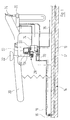
- FIG. 1 at 10 is the ceiling of a building schematically reproduced on which a dental workplace is arranged is.
- a suction line 12 embedded In the building ceiling 10 is a suction line 12 embedded, whose on the right in the drawing End with one located on a floor below central suction unit is connected.
- the latter includes a suction machine and one of them Inlet upstream solid particle and liquid separator.
- a siphon-like storage part 14 In the suction line 12, which in practice consists of several is made of plastic pipes is a siphon-like storage part 14 inserted. That in the drawing left end of the suction line 12 is up angled and stands with a floor junction box 16 in Connection. From this a hose 18 runs to the dental workplace, at which a treatment chair is shown schematically 20, a cuspidor 22, a suction cannula 24, a contact shelf 26 and a total designated 28 Rinsing unit are provided.
- the storage part 14 has a tubular inlet section 30 and a tubular outlet portion coaxial therewith 32. These sections are attached to the pipes of the suction line 12 connected.
- a jam section lies between these two sections 34.
- This has an upper boundary wall 36 with a sloping section 38, seen in side view is circular, with a horizontal section 40 and with a section 42 rising in a straight line.
- the transverse cross section of the stowage section 34 is each essentially rectangular.
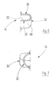
- the modified embodiment according to the figures 4 to 7 is essentially obtained by in the middle shown in FIGS. 2 and 3 of the wall section 50 and the left located storage section reflects at the cutting plane.
- the storage parts according to FIGS. 2 and 4 have in common that a volume of water standing in front of the wall section 48 interrupts the direct passage for air because the overflow formed by the wall section 50 around the Distance s is higher than wall section 40.
- the storage part 14 is in practice a plastic molded part, which e.g. by blowing or by joining two Half-shells can be obtained, the shell joints be glued or welded.
- the Flushing unit 28 a storage container 54, which has a an angled inlet port 58 containing a strainer 56 is connected to the cuspidor 22.
- An upper inlet opening 60 of the storage container 54 is via a solenoid valve 62 with a fresh water line 63 connectable.
- a swivel 64 is pivotally provided inside the storage container 54 . This works together with an invisible reed switch, the is connected to an input of a control unit 66.
- a servo valve 70 is provided which connects to manufacture the hose 18.
- the servo valve 70 has a large flow area and has a magnet-operated Pilot valve, which is controlled by the control unit 66 is controlled.
- a suction pipe 72 Protrudes into the lower section of the storage container 54 a suction pipe 72, which via a line 74 with the Contact shelf 26 is connected and through this with the Hose 18 is connectable.
- the suction system shown in FIG. 1 builds up that formed by the rising wall section 52 A larger overflow when the suction cannula 24 is not used Amount of water provided via the rinsing unit 28 becomes.
- one is continuously operated via the solenoid valve 62 smaller amount of water passed into the storage tank 54. To this come about 22 obtained via the cuspidor Amounts of water.
- the one fed to the hose 18 via the contact rest 26 The amount of water is smaller than that via the solenoid valve 62 amount of water supplied. Therefore the level rises Storage tank 54 on, and the float 64 has one reaches the predetermined height, the control unit 66 controls the servo valve 70.
- the one located in the storage container 54 The volume of water then flows through the hose 18 into the suction line 12 and fills the upstream of the storage part 14 lying section up to the height of the wall section 50. Further water then flows over the wall section 40 into the right of the storage part 14 lying part of the suction line 12.
- the pure water remains as long as the servo valve 70 is open to the tank of the flushing unit 28 solenoid valve 62 closed.
- the suction machine After detaching the suction cannula 24 into the contact holder 26, the suction machine according to a predetermined Time period switched off (assumes that at the other Workplaces no suction cannula is lifted off).
- the control unit 66 for the flushing unit 26 leaves a new one Only fill the suction line 12 when the suction cannula 24 has been removed once in the meantime.
Landscapes
- Health & Medical Sciences (AREA)
- Dentistry (AREA)
- Epidemiology (AREA)
- Life Sciences & Earth Sciences (AREA)
- Animal Behavior & Ethology (AREA)
- General Health & Medical Sciences (AREA)
- Public Health (AREA)
- Veterinary Medicine (AREA)
- Dental Tools And Instruments Or Auxiliary Dental Instruments (AREA)
- External Artificial Organs (AREA)
- Cleaning In General (AREA)
Description
- Figur 1:
- eine Prinzipdarstellung eines dentalen Arbeitsplatzes zusammen mit dem diesem benachbarten Abschnitt einer zentralen Sauganlage;
- Figur 2:
- einen axialen Schnitt durch ein erstes Ausführungsbeispiel eines nieder bauenden Stauteils zur Verwendung in der zentralen Sauganlage nach Figur 1;
- Figur 3:
- eine Aufsicht auf die Oberseite des in Figur 1 gezeigten Stauteils;
- Figur 4:
- einen axialen Schnitt durch ein abgewandeltes, symmetrisches Stauteil;
- Figur 5:
- eine Aufsicht auf das in Figur 4 gezeigte Stauteil;
- Figur 6:
- einen transversalen Halbschnitt durch das Stauteil nach Figur 4 längs der dortigen Schnittlinie VI-VI;
- Figur 7:
- eine Halbaufsicht auf die in Figur 4 rechtsgelegene Stirnfläche des Stauteiles;
- Figur 8:
- einen vertikalen Schnitt durch eine am Arbeitsplatz vorgesehene Spüleinheit der Sauganlage nach Figur 1; und
- Figur 9:
- eine Aufsicht auf einen Speicherbehälter der in Figur 8 gezeigten Spüleinheit, dort von links gesehen.
Claims (6)
- Dentale Sauganlage, vorzugsweise Mehrplatz-Sauganlage, mit einer Saugeinheit, die über mindestens eine Saugleitung (12) mit einem Arbeitsplatz verbunden ist, mit einer Einrichtung zum Aufstauen eines Wasservolumens beim dem Arbeitsplatz benachbarten Ende der Saugleitung und mit einer Einrichtung zur Beaufschlagung des einen Endes des Wasservolumens mit einem über dem von der durch die Saugeinheit erzeugten Unterdruck liegenden Druck, vorzugsweise Atmosphärendruck, dadurch gekennzeichnet, daß die Aufstaueinrichtung ein in einem im wesentlichen horizontalen Abschnitt der Saugleitung (12) angeordnetes Stauteil (14) aufweist, welches mit einem Einlaßabschnitt (30), einem Auslaßabschnitt (32) und einem dazwischenliegenden Stauabschnitt (34) versehen ist, wobei in dem Stauabschnitt (34) eine Überlaufwand (48) vorgesehen ist, wobei der Einlaßabschnitt (30) und der Auslaßabschnitt (32) koaxiale Rohrstutzen sind, wobei der Stauabschnitt (34) eine obere Begrenzungswand (36) aufweist, die einen Abschnitt (40) aufweist, der tiefer (s) liegt als der oberste Punkt (50) der Überlaufwand (48).
- Sauganlage nach Anspruch 1, dadurch gekennzeichnet, daß eine untere Begrenzungswand (44) des Stauabschnittes (34) in radialer Richtung mit der untersten Mantellinie von Einlaßabschnitt (30) und Auslaßabschnitt (32) im wesentlichen fluchtet.
- Sauganlage nach Anspruch 1 oder 2, dadurch gekennzeichnet, daß der Stauabschnitt (34) in transversaler Richtung größere Abmessung aufweist als die Rohrstutzen.
- Sauganlage nach einem der Ansprüche 1 bis 3, dadurch gekennzeichnet, daß das Stauteil (14) zu einer Quermittelebene symmetrisch ausgebildet ist.
- Sauganlage nach einem der Ansprüche 1 bis 4, dadurch gekennzeichnet, daß sich zwischen einer Ablage (26) für eine Saugkanüle (24) und einem Speicherbehälter (54) einer Spüleinheit (28), über welche der Saugleitung (12) Frischwasser zuführbar ist, eine Spülleitung (74) erstreckt, über welche bei abgelegter Saugkanüle (24) aus dem Speicherbehälter (54) laufend eine Wassermenge entnommen und einem zur Saugkanüle (24) führenden Schlauch (18), der mit der Saugleitung (12) verbunden ist, zugeführt wird.
- Sauganlage nach Anspruch 5, dadurch gekennzeichnet, daß die über die Spülleitung (74) abgezogene Wassermenge kleiner ist als eine dem Speicherbehälter (54) von einer Frischwasserleitung (63) zugeführte Wassermenge, und eine der Spüleinheit (28) zugeordnete Steuereinheit (66) ein am Auslaß des Speicherbehälters (54) vorgesehenes Servoventil (70) öffnet, wenn der Flüssigkeitsstand im Speicherbehälter (54) einen vorgegeben Pegel erreicht hat.
Applications Claiming Priority (2)
| Application Number | Priority Date | Filing Date | Title |
|---|---|---|---|
| DE19510462A DE19510462B4 (de) | 1995-03-25 | 1995-03-25 | Dentale Sauganlage |
| DE19510462 | 1995-03-25 |
Publications (2)
| Publication Number | Publication Date |
|---|---|
| EP0734693A1 EP0734693A1 (de) | 1996-10-02 |
| EP0734693B1 true EP0734693B1 (de) | 2000-05-31 |
Family
ID=7757407
Family Applications (1)
| Application Number | Title | Priority Date | Filing Date |
|---|---|---|---|
| EP96103273A Expired - Lifetime EP0734693B1 (de) | 1995-03-25 | 1996-03-03 | Dentales Vakuumdreinagesystem mit Siphon |
Country Status (3)
| Country | Link |
|---|---|
| EP (1) | EP0734693B1 (de) |
| AT (1) | ATE193433T1 (de) |
| DE (2) | DE19510462B4 (de) |
Families Citing this family (1)
| Publication number | Priority date | Publication date | Assignee | Title |
|---|---|---|---|---|
| DE102006008944B4 (de) * | 2006-02-23 | 2010-07-08 | Sirona Dental Systems Gmbh | Zahnärztliche Spüleinheit |
Family Cites Families (7)
| Publication number | Priority date | Publication date | Assignee | Title |
|---|---|---|---|---|
| US1345549A (en) * | 1918-12-26 | 1920-07-06 | Harry P Rawson | Dental appliance |
| GB340180A (en) * | 1929-03-14 | 1930-12-24 | Bois Company Ltd Du | Anti-syphon traps |
| US3012323A (en) * | 1954-02-19 | 1961-12-12 | Vacudent Mfg Company | Method of dentistry and apparatus therefor |
| AT190873B (de) * | 1956-01-05 | 1957-07-25 | Bleiwarenfabrik Gumpoldskirche | Geruchverschluß, insbesondere Fußbodensyphon für Brausebadtassen |
| IT1187187B (it) * | 1985-07-31 | 1987-12-16 | Cattani Off Augusto & Co | Dispositivo separatore e scaricatore di liquidi con pompa di drenaggio,in particolare per impianti di aspirazione odontoiatrici |
| US5017135A (en) * | 1989-10-18 | 1991-05-21 | Ramvac Corporation | Trap and separator for denial vacuum systems |
| DE4205936B4 (de) * | 1992-02-27 | 2005-08-04 | Dürr Dental GmbH & Co. KG | Abscheideeinrichtung |
-
1995
- 1995-03-25 DE DE19510462A patent/DE19510462B4/de not_active Expired - Fee Related
-
1996
- 1996-03-03 AT AT96103273T patent/ATE193433T1/de active
- 1996-03-03 DE DE59605334T patent/DE59605334D1/de not_active Expired - Lifetime
- 1996-03-03 EP EP96103273A patent/EP0734693B1/de not_active Expired - Lifetime
Also Published As
| Publication number | Publication date |
|---|---|
| ATE193433T1 (de) | 2000-06-15 |
| DE19510462B4 (de) | 2008-10-30 |
| DE59605334D1 (de) | 2000-07-06 |
| DE19510462A1 (de) | 1996-09-26 |
| EP0734693A1 (de) | 1996-10-02 |
Similar Documents
| Publication | Publication Date | Title |
|---|---|---|
| EP0047519B1 (de) | Vorrichtung zum Aufsaugen und Aufnehmen von Schlamm | |
| DE3641644C2 (de) | ||
| DE69937941T2 (de) | Behälter für einen zerstäuber der in normaler oder umgekehrter position arbeiten kann | |
| EP0023036B1 (de) | Zahnärztliche Absaugeinrichtung | |
| DE3213554A1 (de) | Fluessigkeits-zuteilungsvorrichtung | |
| DE3208197C1 (de) | Vorrichtung zur automatischen Spuelung von Absaug-Melkanlagen | |
| DE69210004T2 (de) | Vakuumventil für eine Abwassersammelanlage | |
| DE69004638T2 (de) | Rohrverbindungsstruktur und eine Rohrverbindungsstruktur aufnehmende Vakuumabwassersammelvorrichtung. | |
| WO1991004087A1 (de) | Einrichtung zum absaugen von flüssigkeiten | |
| DE3412500A1 (de) | Abscheider fuer schwimm- und sinkstoffe | |
| DE3134940C2 (de) | Dosierpumpe | |
| DE19510462B4 (de) | Dentale Sauganlage | |
| CH438162A (de) | Anlage zum Neutralisieren von Ätzemulsionen | |
| WO2005040501A1 (de) | Drainage-tank mit spülrohr | |
| EP0954649B1 (de) | Vakuumtoilette | |
| CH709137A2 (de) | Schlammabscheider. | |
| EP0088165B1 (de) | Vorrichtung zur automatischen Spülung von Absaug-Melkanlagen | |
| DE4205936A1 (de) | Abscheideeinrichtung | |
| DE102020106593A1 (de) | Reinigungsvorrichtung und Reinigungssystem für eine Blutbehandlungsvorrichtung | |
| DE4008332C2 (de) | Verfahren und Vorrichtung zum Filtern und Aufbereiten von Schmutzwasser | |
| DE102006010569A1 (de) | Unterdruckabwassereinrichtung | |
| EP0633751A1 (de) | Einrichtung an einer zahnärztlichen absauganlage. | |
| DE3112219C2 (de) | Selbstleerender Saugbehälter für die zahnmedizinische Behandlung | |
| DE19950729C1 (de) | Vorrichtung zur Nutzung von Regenwasser für Regen- und Trockenphasenbetrieb | |
| DE1461079C (de) | Vorrichtung zur im wesentlichen kon stanten Zufuhrung einer gereinigten und entlüfteten Papierstoffsuspension zu einer Papiermaschine |
Legal Events
| Date | Code | Title | Description |
|---|---|---|---|
| PUAI | Public reference made under article 153(3) epc to a published international application that has entered the european phase |
Free format text: ORIGINAL CODE: 0009012 |
|
| AK | Designated contracting states |
Kind code of ref document: A1 Designated state(s): AT CH DE IT LI SE |
|
| 17P | Request for examination filed |
Effective date: 19970304 |
|
| 17Q | First examination report despatched |
Effective date: 19990204 |
|
| GRAG | Despatch of communication of intention to grant |
Free format text: ORIGINAL CODE: EPIDOS AGRA |
|
| GRAG | Despatch of communication of intention to grant |
Free format text: ORIGINAL CODE: EPIDOS AGRA |
|
| GRAH | Despatch of communication of intention to grant a patent |
Free format text: ORIGINAL CODE: EPIDOS IGRA |
|
| GRAH | Despatch of communication of intention to grant a patent |
Free format text: ORIGINAL CODE: EPIDOS IGRA |
|
| GRAA | (expected) grant |
Free format text: ORIGINAL CODE: 0009210 |
|
| AK | Designated contracting states |
Kind code of ref document: B1 Designated state(s): AT CH DE IT LI SE |
|
| REF | Corresponds to: |
Ref document number: 193433 Country of ref document: AT Date of ref document: 20000615 Kind code of ref document: T |
|
| REG | Reference to a national code |
Ref country code: CH Ref legal event code: EP |
|
| REF | Corresponds to: |
Ref document number: 59605334 Country of ref document: DE Date of ref document: 20000706 |
|
| ITF | It: translation for a ep patent filed | ||
| EN | Fr: translation not filed | ||
| PG25 | Lapsed in a contracting state [announced via postgrant information from national office to epo] |
Ref country code: SE Free format text: LAPSE BECAUSE OF NON-PAYMENT OF DUE FEES Effective date: 20010304 |
|
| PLBE | No opposition filed within time limit |
Free format text: ORIGINAL CODE: 0009261 |
|
| STAA | Information on the status of an ep patent application or granted ep patent |
Free format text: STATUS: NO OPPOSITION FILED WITHIN TIME LIMIT |
|
| PG25 | Lapsed in a contracting state [announced via postgrant information from national office to epo] |
Ref country code: LI Free format text: LAPSE BECAUSE OF NON-PAYMENT OF DUE FEES Effective date: 20010331 Ref country code: CH Free format text: LAPSE BECAUSE OF NON-PAYMENT OF DUE FEES Effective date: 20010331 |
|
| 26N | No opposition filed | ||
| EUG | Se: european patent has lapsed |
Ref document number: 96103273.7 |
|
| REG | Reference to a national code |
Ref country code: CH Ref legal event code: PL |
|
| PGFP | Annual fee paid to national office [announced via postgrant information from national office to epo] |
Ref country code: IT Payment date: 20100325 Year of fee payment: 15 |
|
| PGFP | Annual fee paid to national office [announced via postgrant information from national office to epo] |
Ref country code: AT Payment date: 20110330 Year of fee payment: 16 |
|
| PGFP | Annual fee paid to national office [announced via postgrant information from national office to epo] |
Ref country code: DE Payment date: 20110530 Year of fee payment: 16 |
|
| PG25 | Lapsed in a contracting state [announced via postgrant information from national office to epo] |
Ref country code: IT Free format text: LAPSE BECAUSE OF NON-PAYMENT OF DUE FEES Effective date: 20110303 |
|
| REG | Reference to a national code |
Ref country code: AT Ref legal event code: MM01 Ref document number: 193433 Country of ref document: AT Kind code of ref document: T Effective date: 20120303 |
|
| PG25 | Lapsed in a contracting state [announced via postgrant information from national office to epo] |
Ref country code: AT Free format text: LAPSE BECAUSE OF NON-PAYMENT OF DUE FEES Effective date: 20120303 |
|
| REG | Reference to a national code |
Ref country code: DE Ref legal event code: R119 Ref document number: 59605334 Country of ref document: DE Effective date: 20121002 |
|
| PG25 | Lapsed in a contracting state [announced via postgrant information from national office to epo] |
Ref country code: DE Free format text: LAPSE BECAUSE OF NON-PAYMENT OF DUE FEES Effective date: 20121002 |