EP0734295B2 - Process for producing thin slabs - Google Patents
Process for producing thin slabs Download PDFInfo
- Publication number
- EP0734295B2 EP0734295B2 EP95906269A EP95906269A EP0734295B2 EP 0734295 B2 EP0734295 B2 EP 0734295B2 EP 95906269 A EP95906269 A EP 95906269A EP 95906269 A EP95906269 A EP 95906269A EP 0734295 B2 EP0734295 B2 EP 0734295B2
- Authority
- EP
- European Patent Office
- Prior art keywords
- casting
- billet
- thickness
- mould
- slag
- Prior art date
- Legal status (The legal status is an assumption and is not a legal conclusion. Google has not performed a legal analysis and makes no representation as to the accuracy of the status listed.)
- Expired - Lifetime
Links
- 238000000034 method Methods 0.000 title claims abstract description 8
- 238000005266 casting Methods 0.000 claims abstract description 36
- 239000002893 slag Substances 0.000 claims abstract description 26
- 239000000843 powder Substances 0.000 claims abstract description 14
- 238000007654 immersion Methods 0.000 claims abstract description 8
- 230000010355 oscillation Effects 0.000 claims abstract description 5
- 238000007711 solidification Methods 0.000 claims abstract description 5
- 230000008023 solidification Effects 0.000 claims abstract description 5
- 238000004519 manufacturing process Methods 0.000 claims abstract description 4
- 239000002184 metal Substances 0.000 claims description 3
- 229910052751 metal Inorganic materials 0.000 claims description 3
- 238000007493 shaping process Methods 0.000 claims 2
- 230000001419 dependent effect Effects 0.000 claims 1
- 230000008018 melting Effects 0.000 claims 1
- 238000002844 melting Methods 0.000 claims 1
- 238000005096 rolling process Methods 0.000 abstract description 7
- 238000009749 continuous casting Methods 0.000 abstract description 4
- 229910000831 Steel Inorganic materials 0.000 abstract description 3
- 239000010959 steel Substances 0.000 abstract description 3
- 238000009434 installation Methods 0.000 abstract 2
- 238000005461 lubrication Methods 0.000 description 4
- 230000005499 meniscus Effects 0.000 description 4
- 230000015572 biosynthetic process Effects 0.000 description 2
- RYGMFSIKBFXOCR-UHFFFAOYSA-N Copper Chemical compound [Cu] RYGMFSIKBFXOCR-UHFFFAOYSA-N 0.000 description 1
- XEEYBQQBJWHFJM-UHFFFAOYSA-N Iron Chemical compound [Fe] XEEYBQQBJWHFJM-UHFFFAOYSA-N 0.000 description 1
- BPQQTUXANYXVAA-UHFFFAOYSA-N Orthosilicate Chemical group [O-][Si]([O-])([O-])[O-] BPQQTUXANYXVAA-UHFFFAOYSA-N 0.000 description 1
- 229910052802 copper Inorganic materials 0.000 description 1
- 239000010949 copper Substances 0.000 description 1
- 230000003247 decreasing effect Effects 0.000 description 1
- 230000007547 defect Effects 0.000 description 1
- 238000011161 development Methods 0.000 description 1
- 230000018109 developmental process Effects 0.000 description 1
- 238000007598 dipping method Methods 0.000 description 1
- 230000009189 diving Effects 0.000 description 1
- 238000011156 evaluation Methods 0.000 description 1
- 238000002474 experimental method Methods 0.000 description 1
- 230000002349 favourable effect Effects 0.000 description 1
- 239000008187 granular material Substances 0.000 description 1
- 230000003993 interaction Effects 0.000 description 1
- 239000007788 liquid Substances 0.000 description 1
- 238000005259 measurement Methods 0.000 description 1
- 239000002245 particle Substances 0.000 description 1
- 239000007787 solid Substances 0.000 description 1
Images


Classifications
-
- B—PERFORMING OPERATIONS; TRANSPORTING
- B22—CASTING; POWDER METALLURGY
- B22D—CASTING OF METALS; CASTING OF OTHER SUBSTANCES BY THE SAME PROCESSES OR DEVICES
- B22D11/00—Continuous casting of metals, i.e. casting in indefinite lengths
- B22D11/12—Accessories for subsequent treating or working cast stock in situ
- B22D11/1206—Accessories for subsequent treating or working cast stock in situ for plastic shaping of strands
-
- B—PERFORMING OPERATIONS; TRANSPORTING
- B22—CASTING; POWDER METALLURGY
- B22D—CASTING OF METALS; CASTING OF OTHER SUBSTANCES BY THE SAME PROCESSES OR DEVICES
- B22D11/00—Continuous casting of metals, i.e. casting in indefinite lengths
- B22D11/10—Supplying or treating molten metal
- B22D11/11—Treating the molten metal
- B22D11/111—Treating the molten metal by using protecting powders
-
- B—PERFORMING OPERATIONS; TRANSPORTING
- B22—CASTING; POWDER METALLURGY
- B22D—CASTING OF METALS; CASTING OF OTHER SUBSTANCES BY THE SAME PROCESSES OR DEVICES
- B22D11/00—Continuous casting of metals, i.e. casting in indefinite lengths
- B22D11/14—Plants for continuous casting
Definitions
- the invention relates to a continuous caster and a method for producing thin slabs.
- the object of the invention is to provide a method which makes it possible to to achieve the predetermined thickness of the thin strand in such a way that optimal conditions for the supply of slag as well as in the reduction of the strand thickness in the mold and in the guide stand during casting rolling.
- the slag height h slag mainly depends on the thickness of the mold inlet cross section and the strand shell height h strand shell depends on the lifting height of the oscillating mold.
- the constant thickness leads to a constant formation of slag over the width of the mold level and thus to one constant slag supply in the area of the meniscus of the entire continuously forming strand shell (3).
- This constant. Slag formation from casting powder or granules (5) over the casting width avoids the Danger of insufficient lubrication between the immersion nozzle and the copper broad side plates. This danger exists since the pouring slag has a glassy structure (silicate structure) with a viscous behavior of approx. 0.5-10 poise.
- an electromagnetic brake in the mold area can clearly show the turbulence in the mold area reduce.
Landscapes
- Engineering & Computer Science (AREA)
- Mechanical Engineering (AREA)
- Continuous Casting (AREA)
- Casting Or Compression Moulding Of Plastics Or The Like (AREA)
- Paper (AREA)
- Yarns And Mechanical Finishing Of Yarns Or Ropes (AREA)
- Moulding By Coating Moulds (AREA)
- Mold Materials And Core Materials (AREA)
- Metal Rolling (AREA)
Abstract
Description
Die Erfindung betrifft eine Stranggießanlage und ein Verfahren zum Erzeugen von Dünnbrammen.The invention relates to a continuous caster and a method for producing thin slabs.
Aus dem Stand der Technik ist es bekannt, flache Tauchausgüsse zu verwenden, z.B. aus DE 37 09 188 A1. Desweiteren sind hydraulisch angetriebene Hubtische üblich, die es erlauben, Hubhöhe, Frequenz und Form der Oszillation durch Abweichen von der Sinusschwingung selbst während des Gießens zu verändern und optimal zu wählen. Bombierte Kokillen sind beispielsweise der DE 41 31 829 A1 und DE 37 24 628 C1 zu entnehmen. Das Gießwalzen, bei dem während der Erstarrung die Gießdicke so reduziert wird, daß eine verbesserte Innenqualität des Stranges erhalten wird, ist u.a. aus der DE 38 18 077 A1 bekannt.It is known from the prior art to use flat immersion spouts, e.g. from DE 37 09 188 A1. Furthermore Hydraulically driven lifting tables are common, which allow lifting height, frequency and shape of the oscillation by deviating from the sinusoidal vibration even during casting and to choose optimally. Bombed molds can be found, for example, in DE 41 31 829 A1 and DE 37 24 628 C1. The casting rolling, in which the casting thickness is reduced so that an improved internal quality of the strand during solidification is obtained is known from DE 38 18 077 A1.
Eine Auswertung des Standes der Technik hat ergeben, daß das Ziel Dünnstränge zu erzeugen, die Lösung komplexer Probleme erfordert und daß die Gesamtheit der beeinflußbaren Variablen über die gesamte Stranggießanlage gesehen so groß ist, daß die Kenntnisse des Durchschnittsfachmannes bei weitem nicht ausreichen und es ihm auch nicht zuzumuten ist, hierfür aus der Vielzahl der möglichen mehr oder weniger brauchbaren Lösungen eine zu finden, die bei gerinstmöglichem Aufwand zu einem zufriedenstellenden Ergebnis führt.An evaluation of the prior art has shown that the goal of producing thin strands, the solution is more complex Problems required and that all the variables that can be influenced over the entire continuous caster seen so large that the knowledge of the average specialist is far from sufficient and so is it it is unreasonable to find one of the multitude of possible more or less usable solutions, which leads to a satisfactory result with the least possible effort.
Aus der WO-A-8801209 ist ein Verfahren und eine Vorrichtung zum Stranggießen von Brammen bekannt, bei der unter Beibehaltung der Querschnittsform der Eingießseite der Kokille über die gesamte Kokillenlänge die Strangschale des Mittenbereiches des aus der Kokille austretenden Stranges durch unmittelbar der Kokille nachgeordnete Stütz-und Führungsmittel verformt wird, und zwar in der Weise, daß sie nach dem Durchgang durch die Verformungsstrecke in der Ebene der Brammenoberfläche des Kantenbereiches liegt.From WO-A-8801209 a method and a device for the continuous casting of slabs is known, in which while maintaining the cross-sectional shape of the pouring side of the mold over the entire length of the mold, the strand shell of the central region of the strand emerging from the mold by support and Guide means is deformed, in such a way that after passing through the deformation path in the plane of the slab surface of the edge area.
Schließlich sei noch auf die DE-Schrift "Stahl und Eisen" (1989, 16.Mai. Nr.9/10, Seiten 453-462) verwiesen. Hieraus ist ein Verfahren und eine Vorrichtung zum Gießen und Gießwalzen dünner Brammen bekannt.Finally, reference is made to the DE publication "Stahl und Eisen" (1989, May 16, No. 9/10, pages 453-462). From this, a method and a device for casting and casting rolls of thin slabs are known.
Aufgabe der Erfindung ist es, ein Verfahren anzugeben, das es möglich macht, eine vorgegebene Dicke des Dünnstranges dadurch zu erreichen, daß optimale Bedingungen bei der Schlackenversorgung sowie bei der Strangdickenreduzierung schon in der Kokille sowie im Führungsgerüst beim Gießwalzen erzielt werden.The object of the invention is to provide a method which makes it possible to to achieve the predetermined thickness of the thin strand in such a way that optimal conditions for the supply of slag as well as in the reduction of the strand thickness in the mold and in the guide stand during casting rolling.
Die Aufgabe wird gelöst durch die Merkmale des Anspruchs 1 Vorteilhafte, nicht platt selbstverständliche
Weiterbildungen enthalten die Unteransprüche. Die Lösung der Aufgabe ist unabhängig vom
Kokillentyp; wie z.B. der Senkrecht-, Senkrechtabbiege- oder Kreisbogenkokille.The object is achieved by the features of
Die Figuren dienen zur Veranschaulichung der folgenden beispielhaften Beschreibung der Erfindung.The figures serve to illustrate the following exemplary description of the invention.
Es zeigen:
- Fig. 1:
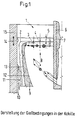
- Darstellung der Gießbedingungen in der Kokille
- Fig. 2:
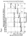
- Technischer Aufwand für gleichbleibende Oberflächenqualität und Gießleistung in Abhängigkeit der Brammendicke bezogen auf eine 200 mm dicke Bramme x 1.000 mm Breite
- Fig. 3.1-3.3:
- Technischer Aufwand für gleichbleibende Oberflächenqualität und Brammendicke in Abhängigkeit von der Gießgeschwindigkeit bezogen auf eine 200 mm dicke Bramme x 1.000 mm Breite
- Fig. 4:
- Hydraulisches Verhalten des Stahles in der Kokille in Abhängigkeit von der Brammendicke bezogen auf eine 200 mm dicke Bramme x 1.000 mm Breite
- Fig. 5:
- Stranggießanlage
- Fig. 1:
- Representation of the casting conditions in the mold
- Fig. 2:
- Technical effort for constant surface quality and casting performance depending on the slab thickness in relation to a 200 mm thick slab x 1,000 mm width
- Fig. 3.1-3.3:
- Technical effort for constant surface quality and slab thickness depending on the casting speed based on a 200 mm thick slab x 1,000 mm width
- Fig. 4:
- Hydraulic behavior of the steel in the mold depending on the slab thickness in relation to a 200 mm thick slab x 1,000 mm width
- Fig. 5:
- continuous casting plant
Im Rahmen der Erarbeitung der Erfindung durchgeführte Versuche haben ergeben, daß die Oberflächenqualität eines Stranges im wesentlichen von der Schlackenführung abhängt. Hierfür ist der Meniskus, d.h. das Zusammenspiel der Schlackenhöhe (hSchlacke) und der aus dem Bad beim Hochschnellen der Kokille heraustretenden Strangschale (hStrangschale) verantwortlich (Fig. 1).Experiments carried out in the course of working out the invention have shown that the surface quality of a strand essentially depends on the slag guidance. This is due to the meniscus, ie the interplay of the slag height (h slag ) and the strand shell (h strand shell ) emerging from the bath when the mold rises (Fig. 1).
Es hat sich ergeben, daß für eine optimale Schmierung und die Vermeidung von Oberflächenfehlern (unmittelbar
unter der Strangoberfläche befindliche Gießpulverteilchen, vorwiegend in Form von Oxiden) das Kriterium
Die Schlackenhöhe hSchlacke ist überwiegend von der Dicke des Kokilleneintrittsquerschnitts und die Strangschalenhöhe hStrangschale von der Hubhöhe der oszillierenden Kokille abhängig.The slag height h slag mainly depends on the thickness of the mold inlet cross section and the strand shell height h strand shell depends on the lifting height of the oscillating mold.
Betrachtet man die Größe hSchlacke und ihre Abhängigkeit von der Dicke des Kokilleneintrittsquerschnitts, so zeigt
die Beziehung
Dieser Zusammenhang zwischen der Dicke im Gießspiegel (19) und der spezifischen Schlackenproduktion und damit der Schlackenhöhe (4) im Meniskus führt auch zu der Notwendigkeit, daß die aktive Gießpulverdicke über die gesamte Gießbeite und damit auch im Bereich des Tauchausgusses konstant zu halten ist.This relationship between the thickness in the mold level (19) and the specific slag production and thus the slag height (4) in the meniscus also leads to the need for the active casting powder thickness to exceed the entire casting work and thus also in the area of the pouring spout must be kept constant.
Die konstante Dicke führt zu einer konstanten Gießschlackenbildung über die Gießspiegelbreite und damit zu einer konstanten Schlackenversorgung im Bereich des Meniskus der gesamten sich kontinuierlich neu bildenden Strangschale (3). Diese konstante. Schlackenbildung aus Gießpulver oder Granulat (5) über die Gießbreite vermeidet die Gefahr einer Mangelschmierung zwischen dem Tauchausguß und den Kupfer-Breitseitenplatten. Diese Gefahr besteht, da die Gießschlacke eine glasige Struktur (Silikat-Struktur) mit einem viskosen Verhalten von ca. 0,5-10 poise aufweist. Durch ihre Zähigkeit kann es zu einer über die Strangbreite gesehen relativen Mangelschmierung im Bereich zwischen Tauchausguß und der Kokillenbreitseite im Vergleich zum restlichen Kokillenbereich im Gießspiegel kommen, wenn der jeweilige Abstand zwischen Tauchausguß und Kokillenbreitseiten kleiner ist als die halbe Strangdicke am Kokillenaustritt.The constant thickness leads to a constant formation of slag over the width of the mold level and thus to one constant slag supply in the area of the meniscus of the entire continuously forming strand shell (3). This constant. Slag formation from casting powder or granules (5) over the casting width avoids the Danger of insufficient lubrication between the immersion nozzle and the copper broad side plates. This danger exists since the pouring slag has a glassy structure (silicate structure) with a viscous behavior of approx. 0.5-10 poise. Due to their toughness, there can be relative lack of lubrication in the area between the string widths Dipping spout and the broadside of the mold in comparison to the remaining mold area in the mold level come when the The respective distance between the immersion nozzle and the broadside of the mold is less than half the strand thickness at the mold outlet.
Betrachtet man dagegen wie sich bei einer festgelegten Gießdicke die Relation (2) bei einer Erhöhung der Gießgeschwindigkeit verändert, wie es in Fig. 3 für eine 75/100 und 125 mm-Kokille dargestellt ist, so stellt man fest, daß diese nur linear - mit einer geringen Steigung der Geraden - zunimmt.If, on the other hand, you look at how the relation (2) increases when the casting speed increases with a defined casting thickness changed, as shown in Fig. 3 for a 75/100 and 125 mm mold, it is found that this only increases linearly - with a slight slope of the straight line.
Von erheblichem Einfluß auf die Relation (1) ist die durch das Einströmen des Metalls in die Kokille entstehende
Turbulenz, die sich häufig bis zum Badspiegel fortsetzt und zu Wellenbewegungen führen kann, wobei die Wellenberge
sich über den Schlackenspiegel hinaus erheben können, was zu einer Unterbrechung in der Schmierung führt. Diese
Turbulenz ist u.a. abhängig vom Durchsatz und der Dicke und Breite der Kokille am Tauchrohraustrittsquerschnitt. Als
ein Maß für die Turbulenz wird nunmehr das hydraulische Verhalten als Quotient von Durchsatz und Dicke definiert und
kann mit folgendem Ausdruck dargestellt werden:
Werte für das hydraulische Verhalten, bezogen auf die 200 mm dicke Bramme, sind beispielsweise der Fig. 4 zu entnehmen. Es zeigt sich, daß größere Kokillendicken ein deutlich günstigeres hydraulisches Verhalten zur Folge haben.Values for the hydraulic behavior, based on the 200 mm thick slab, can be seen in FIG. 4, for example remove. It can be seen that larger mold thicknesses result in significantly more favorable hydraulic behavior to have.
Von Bedeutung bezüglich der Turbulenz ist auch die Relation
Außerdem kann eine elektromagnetische Bremse im Kokillenbereich die Turbulenz im Gießspiegelbereich deutlich verringern.In addition, an electromagnetic brake in the mold area can clearly show the turbulence in the mold area reduce.
Aus den oben aufgestellten und durch Messungen verifizierten Relationen folgt, daß die Verringerung bei der Wahl der Brammendicke am Kokillenaustritt von z.B. 100 mm auf 50 mm und darüber hinaus bei einer Rechteckkokille die Probleme bei der Einhaltung der Relation (1) außerordentlich erhöht. D.h., abgesehen von den Schwierigkeiten bei der Metallzufuhr wird es nahezu unmöglich, auf den geringen Kokilleneintrittsquerschnitt ausreichend Gießpulver aufzubringen, um die entstehende enorm große Strangoberfläche zu schmieren und darüber hinaus die Relation (4) einzustellen. Dagegen läßt sich die Gießgeschwindigkeit bei einer Strangdicke von z.B. 100 mm im Gießspiegel ohne sonderlichen Mehraufwand beträchtlich erhöhen. Das führt zu der überraschenden Lösung, daß es im Bereich des Dünnbrammengießens nicht sinnvoll ist, unbedingt schon am Kokillenaustritt die Brammendicke zu erreichen sondern daß es technisch wesentlich einfacher ist, die Brammendicke, wie sie dem Walzwerk zugeführt wird, darüber hinaus mit Hilfe eines Gießwalzschrittes weiter zu reduzieren und letztlich zu erreichen, wofür sich ein Vielrollengerüst (Segment 0), z.B. ausgebildet als Zangensegment, als vorteilhaft erwiesen hat.From the relations established above and verified by measurements it follows that the reduction in the choice the slab thickness at the mold outlet of e.g. 100 mm to 50 mm and beyond that with a rectangular mold Problems with maintaining the relation (1) increased extraordinarily. That is, apart from the difficulties with Metal supply makes it almost impossible to apply enough casting powder to the small mold inlet cross-section, to lubricate the resulting large strand surface and also to set the relation (4). On the other hand, the casting speed with a strand thickness of e.g. 100 mm in the mold level without considerably increase extra work. This leads to the surprising solution that it is in the range of Thin slab casting is not sensible, it is imperative to reach the slab thickness at the mold outlet, but instead that it is technically much easier to use the slab thickness as it is fed to the rolling mill Using a casting and rolling step to further reduce and ultimately achieve what a multi-roll stand (segment 0), e.g. trained as pliers segment, has proven to be advantageous.
Aus Fig. 5 ist beispielhaft eine Stranggießanlage zu entnehmen, die sämtliche Enfindungsmerkmale enthält.5 shows an example of a continuous caster which contains all the features of the invention.
- 11
- QGießpulver Q casting powder
- 22
- Pulver Tli, Phasengrenze Pulver/SchlackePowder T li , phase boundary powder / slag
- 33
-
hStrangschale,
Höhe Strangschale über Badspiegelh strand shell ,
Height of the strand bowl above the bathroom mirror - 44
-
hSchlacke,
Schlackenhöheh slag ,
slag height - 55
-
hPulver,
Pulverhöheh powder ,
powder height - 66
- TauchausgußA submerged nozzle
- 77
- Ablagerungdeposit
- 88th
- Oxidstrom in die SchlackeOxide flow into the slag
- 99
- Vg = GießgeschwindigkeitV g = casting speed
- 1010
- QSchlacke = SchlackenverbrauchQ slag = slag consumption
- 1111
- Luftair
- 1212
-
Kristallisationsgrenze,
Stahl fest/flüssigFrost line,
Steel solid / liquid - 1313
- Strangschalestrand shell
- 1414
- Oszillation (Hubhöhe, Frequenz, Form)Oscillation (lifting height, frequency, shape)
- 1515
- Kupferplattecopperplate
- 1616
- Verteilerdistributor
- 1717
-
Tauchausguß
Außenmaß z.B. 260 x 60 mm
Innenmaß z.B. 220 x 20 mmA submerged nozzle
External dimensions e.g. 260 x 60 mm
Internal dimensions e.g. 220 x 20 mm - 1818
- optimiertes Gießpulveroptimized casting powder
- 1919
-
75 + 2 x 12 mm x 800 - 1.600 mm,
Brammenformat im Gießspiegel (Meniskus)75 + 2 x 12 mm x 800 - 1,600 mm,
Slab format in the mold level (meniscus) - 2020
-
20 x 220 mm,
Fließquerschnitt - Tauchausguß20 x 220 mm,
Flow cross section - immersion spout - 2121
- hydraulischer Kokillenantriebhydraulic mold drive
- 2222
- FST/FTA ≤ 50*)F ST / F TA ≤ 50 *)
- 2323
-
75 + 2 x 0,5 mm oder 75 mm,
Brammenformat am Kokillenaustritt75 + 2 x 0.5 mm or 75 mm,
Slab format at the mold exit - 2424
- Gelenk oder hydraulischer Zylinder oder ähnlichesArticulated or hydraulic cylinder or the like
- 2525
-
Segment 0, z.B. als Zange ausgebildet
Segment 0, e.g. designed as pliers - 2626
- hydraulischer Zylinder oder ähnlicheshydraulic cylinder or the like
- 2727
-
50 + 2 x 0,5 mm oder 50 mm,
Brammendicke nach dem Gießwalzvorgang50 + 2 x 0.5 mm or 50 mm,
Slab thickness after the casting rolling process - 2828
-
Segment 1 ... n mit hydraulischer Anstellung oder ähnliches
Segment 1 ... n with hydraulic adjustment or similar - 2929
- Vgmax 6 m/minV gmax 6 m / min
- 3030
-
50 + 2 x 0,5 mm oder 50 mm,
Brammendicke am Ende der Strangführung50 + 2 x 0.5 mm or 50 mm,
Slab thickness at the end of the strand guide
Claims (3)
- A method for producing thin slabs, comprising the following steps:the casting powder being supplied such that across the entire width of the slab the active casting powder thickness in the bath level, which has been covered with casting powder beforehand and which is relevant for melting the casting slag, is constant.pouring by means of an immersion nozzle into a convex, oscillating mould, the mould entry cross-section being larger than the mould exit cross-section, whilst observing the condition for the immersion nozzle and the solidification cross-section,FST = billet cross-section of the fully-solidified slab,FTA = cross-section of the outlet of the immersion nozzle,supplying the casting powder on to the metal melt such that the conditionis observed, dependent on the height of oscillation, form and frequency of the mould movement,hbillet shell = height of billet shell above bath level (3),hslag = slag height (4),reducing the billet cross-section immediately beneath the mould in a plurality of steps in a multi-roll stand, in order to build up forced convection in parallel to the continuous reduction in billet thickness in the still-molten interior of the billet, which convection corresponds to the action of the electromagnetic stirrer, the final thickness of the billet being achieved when the core is still molten at the end of the multi-roll stand, andguiding the solidification such that when the final thickness is reached at the exit from the multi-roll stand there are still two phases in the interior of the billet,
- A method according to Claim 1, characterised in that even during the casting the frequency, lifting height and form of oscillation for the mould movement can be freely selected.
- A method according to Claims 1 and 2, characterised in that the mould is constructed such that a residual convex shaping symmetrically to the centre line of the billet is imparted to the billet at the exit from the mould, which convex shaping in thickness is less than 4% of the final thickness.
Applications Claiming Priority (3)
| Application Number | Priority Date | Filing Date | Title |
|---|---|---|---|
| DE4403049 | 1994-01-28 | ||
| DE4403049A DE4403049C1 (en) | 1994-01-28 | 1994-01-28 | Continuous caster and method for producing thin slabs |
| PCT/DE1995/000095 WO1995020445A1 (en) | 1994-01-28 | 1995-01-20 | Continuous casting facility and a process for producing thin slabs |
Publications (3)
| Publication Number | Publication Date |
|---|---|
| EP0734295A1 EP0734295A1 (en) | 1996-10-02 |
| EP0734295B1 EP0734295B1 (en) | 1998-04-01 |
| EP0734295B2 true EP0734295B2 (en) | 2002-05-02 |
Family
ID=6509215
Family Applications (1)
| Application Number | Title | Priority Date | Filing Date |
|---|---|---|---|
| EP95906269A Expired - Lifetime EP0734295B2 (en) | 1994-01-28 | 1995-01-20 | Process for producing thin slabs |
Country Status (14)
| Country | Link |
|---|---|
| US (1) | US6568461B1 (en) |
| EP (1) | EP0734295B2 (en) |
| JP (1) | JP3085978B2 (en) |
| CN (1) | CN1046449C (en) |
| AT (1) | ATE164540T1 (en) |
| AU (1) | AU1453595A (en) |
| BR (1) | BR9506653A (en) |
| CA (1) | CA2181908A1 (en) |
| DE (2) | DE4403049C1 (en) |
| DK (1) | DK0734295T4 (en) |
| ES (1) | ES2114304T5 (en) |
| RU (1) | RU2134178C1 (en) |
| WO (1) | WO1995020445A1 (en) |
| ZA (1) | ZA95671B (en) |
Families Citing this family (12)
| Publication number | Priority date | Publication date | Assignee | Title |
|---|---|---|---|---|
| EP0832704A1 (en) * | 1996-09-19 | 1998-04-01 | Hoogovens Staal B.V. | Continuous casting machine |
| DE19639302C2 (en) * | 1996-09-25 | 2000-02-24 | Schloemann Siemag Ag | Method and device for producing thin slabs on a continuous caster |
| DE19639297C2 (en) * | 1996-09-25 | 2000-02-03 | Schloemann Siemag Ag | Method and device for high-speed continuous casting plants with a reduction in strand thickness during solidification |
| DE19710791C2 (en) * | 1997-03-17 | 2000-01-20 | Schloemann Siemag Ag | Optimized forms of the continuous casting mold and the immersion nozzle for casting steel slabs |
| EP0917922B1 (en) * | 1997-11-21 | 2003-06-25 | SMS Demag AG | Process and plant for continuous casting slabs |
| DE19801822C1 (en) * | 1998-01-15 | 1999-03-18 | Mannesmann Ag | Continuous casting of metals |
| NL1014024C2 (en) * | 2000-01-06 | 2001-07-09 | Corus Technology Bv | Apparatus and method for continuous or semi-continuous casting of aluminum. |
| US20080179036A1 (en) * | 2007-01-26 | 2008-07-31 | Nucor Corporation | Continuous steel slab caster and methods using same |
| US8020605B2 (en) * | 2007-01-26 | 2011-09-20 | Nucor Corporation | Continuous steel slab caster and methods using same |
| ITMI20120046A1 (en) * | 2012-01-18 | 2013-07-19 | Arvedi Steel Engineering S P A | PLANT AND PROCEDURE FOR THE CONTINUOUS QUICK CASTING OF STEEL BRAMME AND STEEL BRAMME |
| RU2718442C1 (en) * | 2016-09-16 | 2020-04-06 | Ниппон Стил Стэйнлесс Стил Корпорейшн | Continuous casting method |
| CN110576163B (en) * | 2019-09-28 | 2021-07-20 | 江苏联峰能源装备有限公司 | Method for producing high-carbon manganese-chromium steel by large-section continuous casting round billet |
Citations (1)
| Publication number | Priority date | Publication date | Assignee | Title |
|---|---|---|---|---|
| DE3423475C2 (en) † | 1984-06-26 | 1986-07-17 | Mannesmann AG, 4000 Düsseldorf | Method and device for the continuous casting of liquid metals, in particular of liquid steel |
Family Cites Families (9)
| Publication number | Priority date | Publication date | Assignee | Title |
|---|---|---|---|---|
| US3318363A (en) * | 1965-03-18 | 1967-05-09 | Oglebay Norton Co | Continuous casting method with degassed glass-like blanket |
| JPS6087959A (en) * | 1983-10-20 | 1985-05-17 | Sumitomo Metal Ind Ltd | Method and device for supplying powder of continuous casting |
| DE3627991A1 (en) * | 1986-08-18 | 1988-02-25 | Mannesmann Ag | METHOD FOR CONTINUOUSLY MOLDING SLABS AND DEVICE FOR CARRYING OUT THE METHOD |
| DE3709188A1 (en) * | 1987-03-20 | 1988-09-29 | Mannesmann Ag | POURING PIPE FOR METALLURGICAL VESSELS |
| EP0317577A4 (en) * | 1987-06-15 | 1989-12-14 | Bell Helicopter Textron Inc | COPILOT QUICK CONNECT Control stick. |
| DE3724628C1 (en) * | 1987-07-22 | 1988-08-25 | Mannesmann Ag | Continuous casting mold for producing thin slabs in slab format |
| DE3818077A1 (en) * | 1988-05-25 | 1989-11-30 | Mannesmann Ag | METHOD FOR CONTINUOUS CASTING ROLLERS |
| DE3823861A1 (en) * | 1988-07-14 | 1990-01-18 | Thyssen Stahl Ag | METHOD AND SYSTEM FOR PRODUCING A STEEL TAPE THICKNESS THAN 10 MM |
| DE4131829C2 (en) * | 1990-10-02 | 1993-10-21 | Mannesmann Ag | Liquid-cooled mold for the continuous casting of steel strands in slab format |
-
1994
- 1994-01-28 DE DE4403049A patent/DE4403049C1/en not_active Expired - Lifetime
-
1995
- 1995-01-20 JP JP07519823A patent/JP3085978B2/en not_active Expired - Lifetime
- 1995-01-20 BR BR9506653A patent/BR9506653A/en not_active IP Right Cessation
- 1995-01-20 CN CN95191381A patent/CN1046449C/en not_active Expired - Fee Related
- 1995-01-20 DE DE59501780T patent/DE59501780D1/en not_active Expired - Lifetime
- 1995-01-20 RU RU96117378A patent/RU2134178C1/en not_active IP Right Cessation
- 1995-01-20 WO PCT/DE1995/000095 patent/WO1995020445A1/en active IP Right Grant
- 1995-01-20 ES ES95906269T patent/ES2114304T5/en not_active Expired - Lifetime
- 1995-01-20 AU AU14535/95A patent/AU1453595A/en not_active Abandoned
- 1995-01-20 AT AT95906269T patent/ATE164540T1/en active
- 1995-01-20 CA CA002181908A patent/CA2181908A1/en not_active Abandoned
- 1995-01-20 EP EP95906269A patent/EP0734295B2/en not_active Expired - Lifetime
- 1995-01-20 DK DK95906269T patent/DK0734295T4/en active
- 1995-01-27 ZA ZA95671A patent/ZA95671B/en unknown
-
1998
- 1998-10-07 US US09/167,776 patent/US6568461B1/en not_active Expired - Fee Related
Patent Citations (1)
| Publication number | Priority date | Publication date | Assignee | Title |
|---|---|---|---|---|
| DE3423475C2 (en) † | 1984-06-26 | 1986-07-17 | Mannesmann AG, 4000 Düsseldorf | Method and device for the continuous casting of liquid metals, in particular of liquid steel |
Non-Patent Citations (1)
| Title |
|---|
| THE I.S.P. TECHNOLOGY, 4th International Iron and Steel Congress, Marrakech (Maroc), October 12-16, 1992 † |
Also Published As
| Publication number | Publication date |
|---|---|
| EP0734295B1 (en) | 1998-04-01 |
| ES2114304T5 (en) | 2002-11-16 |
| ATE164540T1 (en) | 1998-04-15 |
| JP3085978B2 (en) | 2000-09-11 |
| DE59501780D1 (en) | 1998-05-07 |
| WO1995020445A1 (en) | 1995-08-03 |
| DK0734295T3 (en) | 1998-10-19 |
| AU1453595A (en) | 1995-08-15 |
| CN1046449C (en) | 1999-11-17 |
| JPH09508070A (en) | 1997-08-19 |
| ZA95671B (en) | 1995-09-28 |
| DK0734295T4 (en) | 2002-06-17 |
| CN1139892A (en) | 1997-01-08 |
| DE4403049C1 (en) | 1995-09-07 |
| ES2114304T3 (en) | 1998-05-16 |
| CA2181908A1 (en) | 1995-08-03 |
| RU2134178C1 (en) | 1999-08-10 |
| EP0734295A1 (en) | 1996-10-02 |
| US6568461B1 (en) | 2003-05-27 |
| BR9506653A (en) | 1997-09-16 |
Similar Documents
| Publication | Publication Date | Title |
|---|---|---|
| EP0323958B1 (en) | Device for continuous casting of flat slabs | |
| EP0734295B2 (en) | Process for producing thin slabs | |
| EP2349612B1 (en) | Method and continuous casting plant for manufacturing thick slabs | |
| EP3266537A1 (en) | Method and plant for the production of long ingots having a large cross-section | |
| WO1993000191A1 (en) | Immersion casting pipe for thin slabs | |
| EP0834364B1 (en) | Method and device for high-speed continuous casting plants with reduction of the width during solidification | |
| WO2009141207A1 (en) | Method and continuous casting plant for producing thick slabs | |
| EP0741617B1 (en) | Continuous casting facility and process for producing rectangular thin slabs | |
| EP0627968B1 (en) | Process for the continous casting of metal, in particular steel for producing billets and blooms | |
| EP0054867B1 (en) | Method of cooling a continuously cast steel strand | |
| DE4139242A1 (en) | METHOD FOR PRODUCING LONG STEEL PRODUCTS | |
| DE19639299C2 (en) | Device for producing a polygonal or profile format in a continuous caster | |
| EP0865849A1 (en) | Oscillating mould for continuous casting of slabs | |
| WO2009015782A2 (en) | Process for producing steel long products by continuous casting and rolling | |
| WO2002090019A1 (en) | Method and device for continuously casting ingots, slabs or thin slabs | |
| EP0107069A1 (en) | Method of continuously casting metals, in particular steel, and continuous-casting plants for carrying out the method | |
| EP0934786B1 (en) | Process of continuous casting of metal and continuous casting plant for carrying out the method | |
| DE3331575C2 (en) | Process for continuous arc casting of metal, in particular steel | |
| DD148736A5 (en) | CONTINUOUS STEEL MOLDING PROCESS | |
| EP1103321A1 (en) | Configuration of the radii of the strand guiding means in a vertical-curved continuous casting plant | |
| EP3623074A1 (en) | Method for the preparation of long products which are close to final dimensions and a continuous casting and rolling installation for carrying out the method | |
| EP3519124B1 (en) | Method for multiple casting of metal strengths | |
| EP1839776A2 (en) | Strand casting device with a strand casting die for casting liquid metals, in particular for steel grades | |
| DE10144234A1 (en) | Method and device for optimizing the quality of cast strands with round or approximately round cross sections | |
| DE2024747C3 (en) | Process for semicontinuous continuous casting, in particular of steel, and device for carrying out the process * |
Legal Events
| Date | Code | Title | Description |
|---|---|---|---|
| PUAI | Public reference made under article 153(3) epc to a published international application that has entered the european phase |
Free format text: ORIGINAL CODE: 0009012 |
|
| 17P | Request for examination filed |
Effective date: 19960719 |
|
| AK | Designated contracting states |
Kind code of ref document: A1 Designated state(s): AT BE DE DK ES FR GB IT LU NL |
|
| 17Q | First examination report despatched |
Effective date: 19960918 |
|
| GRAG | Despatch of communication of intention to grant |
Free format text: ORIGINAL CODE: EPIDOS AGRA |
|
| GRAG | Despatch of communication of intention to grant |
Free format text: ORIGINAL CODE: EPIDOS AGRA |
|
| GRAH | Despatch of communication of intention to grant a patent |
Free format text: ORIGINAL CODE: EPIDOS IGRA |
|
| GRAH | Despatch of communication of intention to grant a patent |
Free format text: ORIGINAL CODE: EPIDOS IGRA |
|
| GRAA | (expected) grant |
Free format text: ORIGINAL CODE: 0009210 |
|
| AK | Designated contracting states |
Kind code of ref document: B1 Designated state(s): AT BE DE DK ES FR GB IT LU NL |
|
| REF | Corresponds to: |
Ref document number: 164540 Country of ref document: AT Date of ref document: 19980415 Kind code of ref document: T |
|
| ITF | It: translation for a ep patent filed |
Owner name: GUZZI E RAVIZZA S.R.L. |
|
| REF | Corresponds to: |
Ref document number: 59501780 Country of ref document: DE Date of ref document: 19980507 |
|
| REG | Reference to a national code |
Ref country code: ES Ref legal event code: FG2A Ref document number: 2114304 Country of ref document: ES Kind code of ref document: T3 |
|
| GBT | Gb: translation of ep patent filed (gb section 77(6)(a)/1977) |
Effective date: 19980522 |
|
| ET | Fr: translation filed | ||
| REG | Reference to a national code |
Ref country code: DK Ref legal event code: T3 |
|
| PLBQ | Unpublished change to opponent data |
Free format text: ORIGINAL CODE: EPIDOS OPPO |
|
| PLBI | Opposition filed |
Free format text: ORIGINAL CODE: 0009260 |
|
| 26 | Opposition filed |
Opponent name: VOEST-ALPINE INDUSTRIEANLAGENBAU GMBH Effective date: 19981017 |
|
| NLR1 | Nl: opposition has been filed with the epo |
Opponent name: VOEST-ALPINE INDUSTRIEANLAGENBAU GMBH |
|
| PLBF | Reply of patent proprietor to notice(s) of opposition |
Free format text: ORIGINAL CODE: EPIDOS OBSO |
|
| PLBF | Reply of patent proprietor to notice(s) of opposition |
Free format text: ORIGINAL CODE: EPIDOS OBSO |
|
| PLBF | Reply of patent proprietor to notice(s) of opposition |
Free format text: ORIGINAL CODE: EPIDOS OBSO |
|
| RAP2 | Party data changed (patent owner data changed or rights of a patent transferred) |
Owner name: SMS DEMAG AG |
|
| NLT2 | Nl: modifications (of names), taken from the european patent patent bulletin |
Owner name: SMS DEMAG AG |
|
| PLBQ | Unpublished change to opponent data |
Free format text: ORIGINAL CODE: EPIDOS OPPO |
|
| PLAB | Opposition data, opponent's data or that of the opponent's representative modified |
Free format text: ORIGINAL CODE: 0009299OPPO |
|
| R26 | Opposition filed (corrected) |
Opponent name: VOEST-ALPINE INDUSTRIEANLAGENBAU GMBH Effective date: 19981017 |
|
| NLR1 | Nl: opposition has been filed with the epo |
Opponent name: VOEST-ALPINE INDUSTRIEANLAGENBAU GMBH |
|
| PLAW | Interlocutory decision in opposition |
Free format text: ORIGINAL CODE: EPIDOS IDOP |
|
| RTI2 | Title (correction) |
Free format text: PROCESS FOR PRODUCING THIN SLABS |
|
| PLAW | Interlocutory decision in opposition |
Free format text: ORIGINAL CODE: EPIDOS IDOP |
|
| PGFP | Annual fee paid to national office [announced via postgrant information from national office to epo] |
Ref country code: FR Payment date: 20011226 Year of fee payment: 8 |
|
| PGFP | Annual fee paid to national office [announced via postgrant information from national office to epo] |
Ref country code: NL Payment date: 20011227 Year of fee payment: 8 Ref country code: LU Payment date: 20011227 Year of fee payment: 8 |
|
| REG | Reference to a national code |
Ref country code: GB Ref legal event code: IF02 |
|
| PGFP | Annual fee paid to national office [announced via postgrant information from national office to epo] |
Ref country code: DK Payment date: 20020102 Year of fee payment: 8 |
|
| PGFP | Annual fee paid to national office [announced via postgrant information from national office to epo] |
Ref country code: ES Payment date: 20020118 Year of fee payment: 8 |
|
| PGFP | Annual fee paid to national office [announced via postgrant information from national office to epo] |
Ref country code: BE Payment date: 20020220 Year of fee payment: 8 |
|
| PUAH | Patent maintained in amended form |
Free format text: ORIGINAL CODE: 0009272 |
|
| STAA | Information on the status of an ep patent application or granted ep patent |
Free format text: STATUS: PATENT MAINTAINED AS AMENDED |
|
| 27A | Patent maintained in amended form |
Effective date: 20020502 |
|
| AK | Designated contracting states |
Kind code of ref document: B2 Designated state(s): AT BE DE DK ES FR GB IT LU NL |
|
| REG | Reference to a national code |
Ref country code: DK Ref legal event code: T4 |
|
| NLR2 | Nl: decision of opposition | ||
| GBTA | Gb: translation of amended ep patent filed (gb section 77(6)(b)/1977) | ||
| ET3 | Fr: translation filed ** decision concerning opposition | ||
| NLR3 | Nl: receipt of modified translations in the netherlands language after an opposition procedure | ||
| REG | Reference to a national code |
Ref country code: ES Ref legal event code: DC2A Kind code of ref document: T5 Effective date: 20020704 |
|
| PG25 | Lapsed in a contracting state [announced via postgrant information from national office to epo] |
Ref country code: LU Free format text: LAPSE BECAUSE OF NON-PAYMENT OF DUE FEES Effective date: 20030120 |
|
| PG25 | Lapsed in a contracting state [announced via postgrant information from national office to epo] |
Ref country code: ES Free format text: LAPSE BECAUSE OF NON-PAYMENT OF DUE FEES Effective date: 20030121 |
|
| PG25 | Lapsed in a contracting state [announced via postgrant information from national office to epo] |
Ref country code: DK Free format text: LAPSE BECAUSE OF NON-PAYMENT OF DUE FEES Effective date: 20030131 Ref country code: BE Free format text: LAPSE BECAUSE OF NON-PAYMENT OF DUE FEES Effective date: 20030131 |
|
| PG25 | Lapsed in a contracting state [announced via postgrant information from national office to epo] |
Ref country code: NL Free format text: LAPSE BECAUSE OF NON-PAYMENT OF DUE FEES Effective date: 20030801 |
|
| REG | Reference to a national code |
Ref country code: DK Ref legal event code: EBP |
|
| PG25 | Lapsed in a contracting state [announced via postgrant information from national office to epo] |
Ref country code: FR Free format text: LAPSE BECAUSE OF NON-PAYMENT OF DUE FEES Effective date: 20030930 |
|
| NLV4 | Nl: lapsed or anulled due to non-payment of the annual fee |
Effective date: 20030801 |
|
| REG | Reference to a national code |
Ref country code: FR Ref legal event code: ST |
|
| REG | Reference to a national code |
Ref country code: ES Ref legal event code: FD2A Effective date: 20030121 |
|
| PGFP | Annual fee paid to national office [announced via postgrant information from national office to epo] |
Ref country code: GB Payment date: 20100121 Year of fee payment: 16 |
|
| GBPC | Gb: european patent ceased through non-payment of renewal fee |
Effective date: 20110120 |
|
| PG25 | Lapsed in a contracting state [announced via postgrant information from national office to epo] |
Ref country code: GB Free format text: LAPSE BECAUSE OF NON-PAYMENT OF DUE FEES Effective date: 20110120 |
|
| PGFP | Annual fee paid to national office [announced via postgrant information from national office to epo] |
Ref country code: IT Payment date: 20120126 Year of fee payment: 18 |
|
| PGFP | Annual fee paid to national office [announced via postgrant information from national office to epo] |
Ref country code: DE Payment date: 20130122 Year of fee payment: 19 |
|
| PGFP | Annual fee paid to national office [announced via postgrant information from national office to epo] |
Ref country code: AT Payment date: 20130111 Year of fee payment: 19 |
|
| REG | Reference to a national code |
Ref country code: DE Ref legal event code: R119 Ref document number: 59501780 Country of ref document: DE |
|
| REG | Reference to a national code |
Ref country code: AT Ref legal event code: MM01 Ref document number: 164540 Country of ref document: AT Kind code of ref document: T Effective date: 20140120 |
|
| REG | Reference to a national code |
Ref country code: DE Ref legal event code: R119 Ref document number: 59501780 Country of ref document: DE Effective date: 20140801 |
|
| PG25 | Lapsed in a contracting state [announced via postgrant information from national office to epo] |
Ref country code: DE Free format text: LAPSE BECAUSE OF NON-PAYMENT OF DUE FEES Effective date: 20140801 |
|
| PG25 | Lapsed in a contracting state [announced via postgrant information from national office to epo] |
Ref country code: AT Free format text: LAPSE BECAUSE OF NON-PAYMENT OF DUE FEES Effective date: 20140120 |
|
| PG25 | Lapsed in a contracting state [announced via postgrant information from national office to epo] |
Ref country code: IT Free format text: LAPSE BECAUSE OF NON-PAYMENT OF DUE FEES Effective date: 20140120 |