EP0733762A1 - Scharnier für metallische Tür- und Fensterrahmen mit zwei Öffnungsmöglichkeiten - Google Patents
Scharnier für metallische Tür- und Fensterrahmen mit zwei Öffnungsmöglichkeiten Download PDFInfo
- Publication number
- EP0733762A1 EP0733762A1 EP96830138A EP96830138A EP0733762A1 EP 0733762 A1 EP0733762 A1 EP 0733762A1 EP 96830138 A EP96830138 A EP 96830138A EP 96830138 A EP96830138 A EP 96830138A EP 0733762 A1 EP0733762 A1 EP 0733762A1
- Authority
- EP
- European Patent Office
- Prior art keywords
- hinge
- fixed frame
- pin
- fixing
- cylindrical
- Prior art date
- Legal status (The legal status is an assumption and is not a legal conclusion. Google has not performed a legal analysis and makes no representation as to the accuracy of the status listed.)
- Granted
Links
- 239000002184 metal Substances 0.000 title claims abstract description 6
- 230000000295 complement effect Effects 0.000 claims description 3
- 238000010276 construction Methods 0.000 description 2
- 230000000694 effects Effects 0.000 description 1
- 230000000284 resting effect Effects 0.000 description 1
Images

Classifications
-
- E—FIXED CONSTRUCTIONS
- E05—LOCKS; KEYS; WINDOW OR DOOR FITTINGS; SAFES
- E05D—HINGES OR SUSPENSION DEVICES FOR DOORS, WINDOWS OR WINGS
- E05D5/00—Construction of single parts, e.g. the parts for attachment
- E05D5/10—Pins, sockets or sleeves; Removable pins
- E05D5/12—Securing pins in sockets, movably or not
- E05D5/128—Securing pins in sockets, movably or not the pin having a recess or through-hole engaged by a securing member
-
- E—FIXED CONSTRUCTIONS
- E05—LOCKS; KEYS; WINDOW OR DOOR FITTINGS; SAFES
- E05D—HINGES OR SUSPENSION DEVICES FOR DOORS, WINDOWS OR WINGS
- E05D15/00—Suspension arrangements for wings
- E05D15/48—Suspension arrangements for wings allowing alternative movements
- E05D15/52—Suspension arrangements for wings allowing alternative movements for opening about a vertical as well as a horizontal axis
- E05D15/5205—Suspension arrangements for wings allowing alternative movements for opening about a vertical as well as a horizontal axis with horizontally-extending checks
-
- E—FIXED CONSTRUCTIONS
- E05—LOCKS; KEYS; WINDOW OR DOOR FITTINGS; SAFES
- E05Y—INDEXING SCHEME ASSOCIATED WITH SUBCLASSES E05D AND E05F, RELATING TO CONSTRUCTION ELEMENTS, ELECTRIC CONTROL, POWER SUPPLY, POWER SIGNAL OR TRANSMISSION, USER INTERFACES, MOUNTING OR COUPLING, DETAILS, ACCESSORIES, AUXILIARY OPERATIONS NOT OTHERWISE PROVIDED FOR, APPLICATION THEREOF
- E05Y2900/00—Application of doors, windows, wings or fittings thereof
- E05Y2900/10—Application of doors, windows, wings or fittings thereof for buildings or parts thereof
- E05Y2900/13—Type of wing
- E05Y2900/148—Windows
Definitions
- the present invention relates to a hinge for metal door and window frames, in particular for doors and windows with tilt-and-turn twin opening.
- window wings are normally divided into those with conventional opening, which turn about a vertical axis which passes through the hinge supporting the wing (turn opening) and those with tilt opening, that is to say, with a horizontal axis of rotation and the mobile part of the window producing an opening at the top.
- Doors and windows with twin opening, both tilt and turn are increasingly found in this sector; however, for this purpose, both the fixed and mobile parts of the doors and windows must be equipped with a series of accessories (tie rods, rods which limit opening, twin movement handles, etc.) which allow the passage from one configuration to the other following operation of the handle.
- the basic element is always the hinge, which can assume two different configurations as a result of the construction policies implemented by the manufacturer.
- the first consists in always using the same type of hinge, for both wings with conventional opening and wings with tilt-and-turn twin opening; this favours standardisation of the hinges, so that the difference between various portions of the door and window frames used are not evident, especially when fitted in very long walls, where any difference in appearance between the two types of hinges used would be more obvious.
- the second construction policy is, in the case of tilt-and-turn twin opening doors and windows, to use a hinge in which the part of the pin attached to the mobile frame is held, on two sides, by two parts of hinge which can be attached to the fixed frame, so that the part which supports the mobile part of the hinge (i.e.: attached to the mobile part of the door or window) is not inserted over the pin and resting on the lower fixed part, thus increasing the possibility of supporting large, heavy doors and windows.
- this may give rise to unacceptable discontinuity.
- the object of the present invention is, therefore, to overcome the afore-mentioned disadvantages by creating a hinge with components which also make it suitable for use as a "return" type hinge, that is to say, suitable for very heavy wings, keeping production down to one type of hinge and minimising the negative aesthetic effects arising from the alternate use of hinges both of the standard two-part type and the "return" type.
- the present invention relates to a hinge with a pin which extends for a value greater than the length of the corresponding pivot seat defined by two half-hinges which form the hinge and in which means for fixing the part of the pin protruding from the hinge to the fixed frame are envisaged.
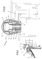
- the first half-hinge 2 has means for its attachment to a first section of a fixed frame 5, said means being the screws 28 in the figure.
- the second half-hinge 3 can be attached to a second section of a mobile frame 6.
- the mobile frame 6 is schematically represented by the parts for connection to the frame itself.
- other components which are not strictly part of the present invention are not numbered.
- the two half-hinges pivot respectively about a cylindrical pin 4 which may be inserted in a relative cylindrical seat 7 which extends longitudinally for a first value L7.
- the seat 7 is defined by corresponding longitudinal cylindrical cavities in the two half-hinges 2, 3.
- the pin 4 advantageously, extends longitudinally for a second value L4, greater than the first value L7.
- One end 8 of the pin 4 protrudes from the seat 7 and fixing means 9 are envisaged to fix the end 8 to the first section of the fixed frame 5.
- the end 8 of the pin 4 has a first through-hole 10 and the fixing means 9 include an element 11 for fixing to the fixed frame 5, said element having a shank 12 which can be inserted into the through-hole 10 and fixed to the fixed frame 5, and a head 13 with diameter D13 greater than the diameter D10 of the through-hole 10, so as to attach the pin 4 to the fixed frame 5 with a second attachment, in addition to that defined by the first half-hinge 2 with the screws 28.
- a cradle element 14 with a second through-hole 15 and a section of concave cylindrical surface which complements the shape of the pin 4 is envisaged.
- the fixing element 11 can be inserted in the second through-hole 15.
- a bushing 16 is envisaged for fixing to the fixed frame 5.
- Said bushing can be inserted in a corresponding circular seat 17 in the fixed frame 5 and has a cylindrical connecting portion 18, to the exterior of which the cradle element 14 may be attached, and into the interior of which the shank 12 of the fixing element 11 can be stably fitted.
- the fixing element 11 is a screw, and the shank is, therefore, threaded, the interior of the cylindrical connecting portion 18 is threaded in such a way as to complement the thread of the shank 12, as shown in the accompanying drawings.
- the cylindrical connecting portion 18 has a groove 19 and, at the second through-hole 15, the cradle element 14 has a series of teeth 20 which can be inserted in the groove 19 so as to stably fix the cradle element 14 to the bushing 16 once attached to the cylindrical connecting portion 18.
- a cover element 21 is envisaged to cover the upper end of the pin 4 and the fixing means 9 as well as to level the upper part of the hinge with the remaining part consisting of the two half-hinges 2, 3.
- the cover element 21 has an internal cavity 23 which complements the fixing means 9 in their active configuration (that is to say, when they are attached to the pin 4 and the fixed frame 5) and an external surface whose shape and size depends upon the corresponding external or visible surfaces of the half-hinges 2, 3.
- the cover element 21 consists of a substantially tubular open body and the internal cavity 23 has a pair of longitudinal grooves 25 which define a pair of guides.
- the cradle element 14 has a pair of longitudinal tabs or ribs 24, which can be stably inserted in the longitudinal grooves 25 of the cover element 21.
- the cradle element 14 has a series of pointed protrusions 26, designed to interact with the face of the fixed frame 5 so as to lock the cradle element 14 to the fixed frame 5.
- the cradle element 14 is attached to the cylindrical portion 18 of the bushing 16, remaining integral with the bushing 16 and the fixed frame 5.
- the fixing element 11 is inserted in the first hole 10 and second hole 17, screwing into the thread inside the bushing 16.
Landscapes
- Engineering & Computer Science (AREA)
- Mechanical Engineering (AREA)
- Hinges (AREA)
Applications Claiming Priority (2)
| Application Number | Priority Date | Filing Date | Title |
|---|---|---|---|
| ITBO950115 | 1995-03-22 | ||
| IT95BO000115A IT1280402B1 (it) | 1995-03-22 | 1995-03-22 | Cerniera per infissi metallici a doppia apertura |
Publications (2)
| Publication Number | Publication Date |
|---|---|
| EP0733762A1 true EP0733762A1 (de) | 1996-09-25 |
| EP0733762B1 EP0733762B1 (de) | 1998-06-17 |
Family
ID=11340414
Family Applications (1)
| Application Number | Title | Priority Date | Filing Date |
|---|---|---|---|
| EP96830138A Expired - Lifetime EP0733762B1 (de) | 1995-03-22 | 1996-03-21 | Scharnier für metallische Tür- und Fensterrahmen mit zwei Öffnungsmöglichkeiten |
Country Status (3)
| Country | Link |
|---|---|
| EP (1) | EP0733762B1 (de) |
| DE (1) | DE69600359D1 (de) |
| IT (1) | IT1280402B1 (de) |
Cited By (2)
| Publication number | Priority date | Publication date | Assignee | Title |
|---|---|---|---|---|
| CN101498189A (zh) * | 2008-01-31 | 2009-08-05 | 萨维奥股份有限公司 | 用于门或窗的铰链 |
| ES2376469A1 (es) * | 2009-03-24 | 2012-03-14 | Julian Narro García | Dispositivo de hoja oscilobatiente para ventanas y similares. |
Citations (2)
| Publication number | Priority date | Publication date | Assignee | Title |
|---|---|---|---|---|
| DE4302599C1 (de) * | 1993-01-30 | 1994-02-24 | Bilstein August Gmbh Co Kg | Vorrichtung zum Verbinden eines Ausstellenkers mit einem Fenster- oder Türrahmen |
| DE9215565U1 (de) * | 1992-11-16 | 1994-03-17 | Hahn Gmbh & Co Kg Dr | Band für Türen, Fenster u.dgl. |
-
1995
- 1995-03-22 IT IT95BO000115A patent/IT1280402B1/it active IP Right Grant
-
1996
- 1996-03-21 EP EP96830138A patent/EP0733762B1/de not_active Expired - Lifetime
- 1996-03-21 DE DE69600359T patent/DE69600359D1/de not_active Expired - Lifetime
Patent Citations (2)
| Publication number | Priority date | Publication date | Assignee | Title |
|---|---|---|---|---|
| DE9215565U1 (de) * | 1992-11-16 | 1994-03-17 | Hahn Gmbh & Co Kg Dr | Band für Türen, Fenster u.dgl. |
| DE4302599C1 (de) * | 1993-01-30 | 1994-02-24 | Bilstein August Gmbh Co Kg | Vorrichtung zum Verbinden eines Ausstellenkers mit einem Fenster- oder Türrahmen |
Cited By (4)
| Publication number | Priority date | Publication date | Assignee | Title |
|---|---|---|---|---|
| CN101498189A (zh) * | 2008-01-31 | 2009-08-05 | 萨维奥股份有限公司 | 用于门或窗的铰链 |
| EP2085548A1 (de) * | 2008-01-31 | 2009-08-05 | SAVIO S.p.A. | Ein Scharnier für Türen oder Fenster |
| US7996960B2 (en) | 2008-01-31 | 2011-08-16 | Savio S.P.A. | Hinge for doors or windows |
| ES2376469A1 (es) * | 2009-03-24 | 2012-03-14 | Julian Narro García | Dispositivo de hoja oscilobatiente para ventanas y similares. |
Also Published As
| Publication number | Publication date |
|---|---|
| DE69600359D1 (de) | 1998-07-23 |
| IT1280402B1 (it) | 1998-01-20 |
| EP0733762B1 (de) | 1998-06-17 |
| ITBO950115A1 (it) | 1996-09-22 |
| ITBO950115A0 (it) | 1995-03-22 |
Similar Documents
| Publication | Publication Date | Title |
|---|---|---|
| US20040163211A1 (en) | Hinge | |
| HU222755B1 (hu) | Támasztószerkezet árnyékolószerkezetekhez, tetőablak, valamint árnyékolószerkezet ilyen tetőablakhoz | |
| US5035081A (en) | Double-hung window | |
| EP0733762B1 (de) | Scharnier für metallische Tür- und Fensterrahmen mit zwei Öffnungsmöglichkeiten | |
| GB2070129A (en) | A Hinge | |
| CZ299584B6 (cs) | Záves pro dvere, okna a podobné | |
| EP0415868A1 (de) | Verbessertes Scharnier | |
| US5095583A (en) | Folding-arm bearing for an oscillating-swinging leaf | |
| US6170555B1 (en) | Corner assembly for a frame | |
| KR20050074640A (ko) | 캐비넷의 프런트 도어의 핸들 구조 | |
| GB2280475A (en) | Window stay | |
| CN215889620U (zh) | 一种双向传动器 | |
| KR930012077B1 (ko) | 알루미늄 창호의 조립구조 | |
| KR20020011199A (ko) | 걸이식 미닫이 문 및 매달린 바퀴 | |
| JPS6334075Y2 (de) | ||
| JPH022877Y2 (de) | ||
| KR200149276Y1 (ko) | 가구용 힌지 | |
| CN221169037U (zh) | 一种极窄的门窗执手 | |
| JP2944397B2 (ja) | 自動車用ドアミラーのバイザー補強構造 | |
| KR200238204Y1 (ko) | 창호용 방풍구 | |
| JPH0415358B2 (de) | ||
| KR20190002676U (ko) | 스윙 도어 | |
| EP0736656B1 (de) | Verriegelungselement für Tür- oder Fensterrahmen aus Metall | |
| CN209384784U (zh) | 一种门窗可调节滚轴简易安装锁座 | |
| KR200406889Y1 (ko) | 외부은폐형 도어힌지 |
Legal Events
| Date | Code | Title | Description |
|---|---|---|---|
| PUAI | Public reference made under article 153(3) epc to a published international application that has entered the european phase |
Free format text: ORIGINAL CODE: 0009012 |
|
| AK | Designated contracting states |
Kind code of ref document: A1 Designated state(s): DE ES FR GR IT |
|
| 17P | Request for examination filed |
Effective date: 19970110 |
|
| 17Q | First examination report despatched |
Effective date: 19970225 |
|
| GRAG | Despatch of communication of intention to grant |
Free format text: ORIGINAL CODE: EPIDOS AGRA |
|
| GRAG | Despatch of communication of intention to grant |
Free format text: ORIGINAL CODE: EPIDOS AGRA |
|
| GRAH | Despatch of communication of intention to grant a patent |
Free format text: ORIGINAL CODE: EPIDOS IGRA |
|
| GRAH | Despatch of communication of intention to grant a patent |
Free format text: ORIGINAL CODE: EPIDOS IGRA |
|
| GRAA | (expected) grant |
Free format text: ORIGINAL CODE: 0009210 |
|
| AK | Designated contracting states |
Kind code of ref document: B1 Designated state(s): DE ES FR GR IT |
|
| PG25 | Lapsed in a contracting state [announced via postgrant information from national office to epo] |
Ref country code: GR Free format text: LAPSE BECAUSE OF NON-PAYMENT OF DUE FEES Effective date: 19980617 Ref country code: FR Free format text: LAPSE BECAUSE OF FAILURE TO SUBMIT A TRANSLATION OF THE DESCRIPTION OR TO PAY THE FEE WITHIN THE PRESCRIBED TIME-LIMIT Effective date: 19980617 Ref country code: ES Free format text: THE PATENT HAS BEEN ANNULLED BY A DECISION OF A NATIONAL AUTHORITY Effective date: 19980617 |
|
| ITF | It: translation for a ep patent filed | ||
| REF | Corresponds to: |
Ref document number: 69600359 Country of ref document: DE Date of ref document: 19980723 |
|
| PG25 | Lapsed in a contracting state [announced via postgrant information from national office to epo] |
Ref country code: DE Free format text: LAPSE BECAUSE OF FAILURE TO SUBMIT A TRANSLATION OF THE DESCRIPTION OR TO PAY THE FEE WITHIN THE PRESCRIBED TIME-LIMIT Effective date: 19980918 |
|
| EN | Fr: translation not filed | ||
| PLBE | No opposition filed within time limit |
Free format text: ORIGINAL CODE: 0009261 |
|
| STAA | Information on the status of an ep patent application or granted ep patent |
Free format text: STATUS: NO OPPOSITION FILED WITHIN TIME LIMIT |
|
| 26N | No opposition filed | ||
| PGFP | Annual fee paid to national office [announced via postgrant information from national office to epo] |
Ref country code: IT Payment date: 20060331 Year of fee payment: 11 |
|
| PG25 | Lapsed in a contracting state [announced via postgrant information from national office to epo] |
Ref country code: IT Free format text: LAPSE BECAUSE OF NON-PAYMENT OF DUE FEES Effective date: 20070321 |