EP0733536B1 - Electric power steering device - Google Patents
Electric power steering device Download PDFInfo
- Publication number
- EP0733536B1 EP0733536B1 EP96301928A EP96301928A EP0733536B1 EP 0733536 B1 EP0733536 B1 EP 0733536B1 EP 96301928 A EP96301928 A EP 96301928A EP 96301928 A EP96301928 A EP 96301928A EP 0733536 B1 EP0733536 B1 EP 0733536B1
- Authority
- EP
- European Patent Office
- Prior art keywords
- motor
- control circuit
- end frame
- electric power
- housing
- Prior art date
- Legal status (The legal status is an assumption and is not a legal conclusion. Google has not performed a legal analysis and makes no representation as to the accuracy of the status listed.)
- Expired - Lifetime
Links
Images


Classifications
-
- B—PERFORMING OPERATIONS; TRANSPORTING
- B62—LAND VEHICLES FOR TRAVELLING OTHERWISE THAN ON RAILS
- B62D—MOTOR VEHICLES; TRAILERS
- B62D5/00—Power-assisted or power-driven steering
- B62D5/04—Power-assisted or power-driven steering electrical, e.g. using an electric servo-motor connected to, or forming part of, the steering gear
- B62D5/0403—Power-assisted or power-driven steering electrical, e.g. using an electric servo-motor connected to, or forming part of, the steering gear characterised by constructional features, e.g. common housing for motor and gear box
- B62D5/0406—Power-assisted or power-driven steering electrical, e.g. using an electric servo-motor connected to, or forming part of, the steering gear characterised by constructional features, e.g. common housing for motor and gear box including housing for electronic control unit
-
- H—ELECTRICITY
- H01—ELECTRIC ELEMENTS
- H01R—ELECTRICALLY-CONDUCTIVE CONNECTIONS; STRUCTURAL ASSOCIATIONS OF A PLURALITY OF MUTUALLY-INSULATED ELECTRICAL CONNECTING ELEMENTS; COUPLING DEVICES; CURRENT COLLECTORS
- H01R39/00—Rotary current collectors, distributors or interrupters
- H01R39/02—Details for dynamo electric machines
- H01R39/38—Brush holders
- H01R39/385—Means for mechanical fixation of the brush holder
-
- H—ELECTRICITY
- H02—GENERATION; CONVERSION OR DISTRIBUTION OF ELECTRIC POWER
- H02K—DYNAMO-ELECTRIC MACHINES
- H02K11/00—Structural association of dynamo-electric machines with electric components or with devices for shielding, monitoring or protection
- H02K11/30—Structural association with control circuits or drive circuits
- H02K11/33—Drive circuits, e.g. power electronics
-
- H—ELECTRICITY
- H02—GENERATION; CONVERSION OR DISTRIBUTION OF ELECTRIC POWER
- H02K—DYNAMO-ELECTRIC MACHINES
- H02K23/00—DC commutator motors or generators having mechanical commutator; Universal AC/DC commutator motors
- H02K23/66—Structural association with auxiliary electric devices influencing the characteristic of, or controlling, the machine, e.g. with impedances or switches
-
- H—ELECTRICITY
- H02—GENERATION; CONVERSION OR DISTRIBUTION OF ELECTRIC POWER
- H02K—DYNAMO-ELECTRIC MACHINES
- H02K5/00—Casings; Enclosures; Supports
- H02K5/04—Casings or enclosures characterised by the shape, form or construction thereof
- H02K5/14—Means for supporting or protecting brushes or brush holders
- H02K5/143—Means for supporting or protecting brushes or brush holders for cooperation with commutators
- H02K5/148—Slidably supported brushes
-
- H—ELECTRICITY
- H02—GENERATION; CONVERSION OR DISTRIBUTION OF ELECTRIC POWER
- H02K—DYNAMO-ELECTRIC MACHINES
- H02K7/00—Arrangements for handling mechanical energy structurally associated with dynamo-electric machines, e.g. structural association with mechanical driving motors or auxiliary dynamo-electric machines
- H02K7/10—Structural association with clutches, brakes, gears, pulleys or mechanical starters
- H02K7/108—Structural association with clutches, brakes, gears, pulleys or mechanical starters with friction clutches
- H02K7/1085—Magnetically influenced friction clutches
-
- H—ELECTRICITY
- H02—GENERATION; CONVERSION OR DISTRIBUTION OF ELECTRIC POWER
- H02K—DYNAMO-ELECTRIC MACHINES
- H02K5/00—Casings; Enclosures; Supports
- H02K5/04—Casings or enclosures characterised by the shape, form or construction thereof
- H02K5/22—Auxiliary parts of casings not covered by groups H02K5/06-H02K5/20, e.g. shaped to form connection boxes or terminal boxes
- H02K5/225—Terminal boxes or connection arrangements
-
- H—ELECTRICITY
- H02—GENERATION; CONVERSION OR DISTRIBUTION OF ELECTRIC POWER
- H02K—DYNAMO-ELECTRIC MACHINES
- H02K9/00—Arrangements for cooling or ventilating
- H02K9/28—Cooling of commutators, slip-rings or brushes e.g. by ventilating
Definitions
- the EPS is mounted to a vehicle at a lower position in the engine room, and is exposed to undesirable environmental conditions so that it is submerged in the water depending upon the running speed even though the depth of water may be small and it is subjected to muddy water and snow adhered thereto. Therefore, the control circuit of the EPS is usually arranged inside the passenger compartment where the environment is favorable.
- the motor and the control circuit with the motor housing are arranged in thermal contact with the rack housing.
- the rack housing is preferably made of aluminum and has a large thermal capacity and a small heat resistance. Therefore, the rack housing suitably absorbs heat transmitted from the motor housing, so that heat generated by the motor and the control circuit is efficiently radiated through the motor housing to the rack housing and the temperature in the motor housing is maintained relatively low. Accordingly, the stable operation of the electric power steering device is guaranteed.
- the motor housing comprises an end frame having the motor and the control circuit assembled thereonto, and a cup-shaped motor case covering the motor and the control circuit and hermetically coupled to the end frame, the end frame being fixed to the rack housing.
- the whole motor housing is of a water-proof structure, and the connector for connection to external units can be hermetically passed through the motor case without impairing waterproof characteristics.
- a motor wiring connecting the control circuit 9 (switching elements 33) to the motor 5 (brushes 22) is realized by using connection terminals 43 provided on the control circuit 9. That is, pigtails 44 (see Figs. 2 and 8) leading from the brushes 22 are usually made of a copper mesh wire to provide lower resistance, and on the other hand, the connection of the switching elements 33 is carried out by bonding wires 45.
- the brushes 22 and the switching elements 33 are coupled in a different manner.
- this embodiment employs the layout structure shown in Fig. 1 in order to obtain good heat-radiating performance without impairing functions of the constituent parts.
Landscapes
- Engineering & Computer Science (AREA)
- Power Engineering (AREA)
- Microelectronics & Electronic Packaging (AREA)
- Chemical & Material Sciences (AREA)
- Combustion & Propulsion (AREA)
- Transportation (AREA)
- Mechanical Engineering (AREA)
- Power Steering Mechanism (AREA)
- Motor Or Generator Current Collectors (AREA)
- Motor Or Generator Cooling System (AREA)
Description
- The present invention relates to an electric power steering device for assisting the steering operation.
- Nowadays, an electric power steering device (hereinafter abbreviated as EPS) has been put into practical use, according to which the steering operation is assisted by the rotational output of a motor. The EPS is constituted by a motor for assisting the steering power, a torque sensor for detecting the steering torque, an electromagnetic clutch for disconnecting the motor from the steering mechanism under abnormal condition, and a control circuit for controlling the motor current based upon signals detected by the torque sensor, a vehicle speed sensor and other sensors. For example, EP-A-0535422 discloses an electric power steering apparatus for a vehicle having a steering system including a steering mechanism accommodated in a rack shaft case, the electric power steering apparatus comprising: an output shaft which is connected to the steering apparatus; a motor for torque-assisting the steering apparatus via the output shaft; a signal processing circuit to provide signals to a control circuit which controls the motor; and a motor housing for accommodating the motor, said motor housing being arranged in thermal contact with the rack housing. The EPS is mounted to a speed sensor and other sensors. The EPS is mounted to a vehicle at a lower position in the engine room, and is exposed to undesirable environmental conditions so that it is submerged in the water depending upon the running speed even though the depth of water may be small and it is subjected to muddy water and snow adhered thereto. Therefore, the control circuit of the EPS is usually arranged inside the passenger compartment where the environment is favorable.
- The conventional electric power steering devices, however, involve the following problems.
- (1) The control circuit has many signal lines that are connected to the motor, the electric clutch, the rotational angle sensor for detecting the steering angle, and the like units. Therefore, many connectors are used for connecting these signal lines, causing the control circuit to become bulky. Furthermore, defective contact of the connectors may occur with an increase in the number of the connectors.
- (2) In order to mount the control circuit in the passenger compartment, the signal lines must pass through a partitioning wall between the compartment and the engine room, so an increased number of assembling steps are required for accomplishing the connection. In particular, the wiring for flowing a large motor current therethrough is thick from the standpoint of decreasing wiring resistance, and is not easy to handle.
- (3) In the EPS, the motor current is controlled by the switching operation of transistors, so electromagnetic noise occurs due to the switching operation of the transistors.
-
- The present invention was accomplished in view of the above-mentioned circumstances, and its object is to provide an electric power steering device which is small in size, requires a simplified wiring, generates less electromagnetic noise, and features high reliability.
- According to the present invention, there is provided an electric power steering device for an automobile having a steering system including a steering mechanism accommodated in rack housing, the electric power steering device comprising an output shaft coupled to the steering mechanism, a motor for torque-assisting the steering mechanism via said output shaft, a control circuit for controlling the motor, and a motor housing for accommodating the motor, said motor housing being arranged in thermal contact with the rack housing;
characterised in that: - the motor housing also accommodates the control circuit therewithin;
- the motor housing is secured to the rack housing; and
- the motor and the control circuit are in thermal contact with the rack housing via the motor housing.
-
- In this arrangement, the control circuit and the motor can be accommodated in the common motor housing, and it is possible to electrically connect the control circuit to the motor within the motor housing. By connecting the control circuit to the motor within the motor housing, it is not necessary to connect the control circuit to external units by wirings, so that the number of the necessary harnesses can be decreased. Accordingly, it is possible to reduce defective signal contacts of the connectors or damages to harnesses in the whole system, to thereby greatly improve reliability.
- In addition, the motor and the control circuit with the motor housing are arranged in thermal contact with the rack housing. The rack housing is preferably made of aluminum and has a large thermal capacity and a small heat resistance. Therefore, the rack housing suitably absorbs heat transmitted from the motor housing, so that heat generated by the motor and the control circuit is efficiently radiated through the motor housing to the rack housing and the temperature in the motor housing is maintained relatively low. Accordingly, the stable operation of the electric power steering device is guaranteed.
- Preferably, the motor housing comprises an end frame having the motor and the control circuit assembled thereonto, and a cup-shaped motor case covering the motor and the control circuit and hermetically coupled to the end frame, the end frame being fixed to the rack housing. As a result, the whole motor housing is of a water-proof structure, and the connector for connection to external units can be hermetically passed through the motor case without impairing waterproof characteristics.
- Preferably, a coating material having a small thermal resistance and a good sealing property is applied between adjoining surfaces of the end frame and the rack housing. Therefore, heat is transferred from the end frame to the rack housing while the internal space in the motor housing is in an air-tight condition.
- Preferably, the end frame is integrally provided with a thin heat-radiating plate, and the control circuit is assembled so that it thermally contacts the heat-radiating plate. Therefore, the heat resistance between the control circuit and the end frame is decreased and it possible to suppress the rise of temperature of the control circuit.
- The present invention will become more apparent from the following description of the preferred embodiments, with reference to the accompanying drawings, in which:
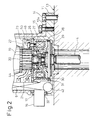
- Fig. 1 is a cross-sectional view illustrating the motor housing and the rack housing of the electric power steering device according to the embodiment of the present invention;
- Fig. 2 is an enlarged cross-sectional view of a portion of the motor housing and the rack housing of Fig. 1;
- Fig. 3 is a diagram illustrating the steering system including the electric power steering device;
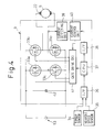
- Fig. 4 is a block diagram illustrating the internal constitution of the control circuit;
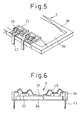
- Fig. 5 is a perspective view illustrating connection terminals of the control circuit;
- Fig. 6 is a side cross-sectional view illustrating connection terminals of the control circuit;
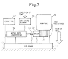
- Fig. 7 is a model diagram illustrating the flow of heat;
- Fig. 8 is a plan view illustrating the control circuit and the brushes;
- Fig. 9 is a side view illustrating the pigtails;
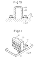
- Fig. 10 is a cross-sectional view illustrating the brush holder;
- Fig. 11 is a perspective view illustrating the brush holder; and
- Fig. 12 is a cross-sectional view illustrating the mounting of the control circuit.
-
- An embodiment of the electric power steering device (EPS) of the present invention will now be described with reference to the drawings.
- Figures 1 and 2 show the internal structure of the electric power steering device (EPS), and Fig. 3 shows the steering system including electric power steering device of Figs. 1 and 2.
- As shown in Fig. 3, the steering system of an automobile has a steering wheel 8, and a
steering mechanism 3 coupled to the steering wheel 8 via a steering column for movingwheels 54 of the automobile. The EPS 1 includes anoutput shaft 4 coupled to thesteering mechanism 3 via areduction gear 2, amotor 5 for producing a rotational output, anelectromagnetic clutch 6 for transmitting the rotational output of themotor 5 to theoutput shaft 4, asteering angle sensor 7 for detecting the steering angle (rotational angle of the output shaft 4), and acontrol circuit 9 for controlling the motor current depending upon the steering force of a steering wheel 8 and the vehicle speed. These constituent parts (motor 5,electromagnetic clutch 6,steering angle sensor 7, control circuit 9) other than theoutput shaft 4 are constituted in a unitary structure and are accommodated in a motor housing 10 (see Fig. 1). - Referring to Fig. 1, the
motor housing 10 comprises anend frame 11 to which the above-mentioned parts are mounted, and amotor case 12 hermetically fitted to theend frame 11 for enclosing the constituent parts. Theend frame 11 is intimately attached to the end surface of arack housing 13 which accommodates thesteering mechanism 3 and is made of a material (e.g., aluminum) having good heat conductivity. Theend frame 11 is then secured to therack housing 13 by tighteningbolts 14. Themotor case 12 is made of a magnetic material (e.g., steel), shaped in a cylindrical shape with one closed end (upper end in Fig. 1), i.e., in the shape of a cup, and secured at itsfixing portions 12a to theend frame 11 by tighteningbolts 15. A passage opening 17 (Fig. 2) is formed in the open end portion of themotor case 12 and theend frame 11 to allow aconnector 16 to extend therethrough for electrically connecting thecontrol circuit 9 to external units (not shown). - The
motor 5 comprises a field device (e.g., a cylindrical magnet shown in Fig. 1) 18, anarmature 19 that revolves along the inner periphery of themagnet 18, acommutator 21 provided on one end of ashaft 20, brushes 22 (see Figs. 2 and 8) that are brought into sliding contact with the outer peripheral surface of thecommutator 21, and abrush holder 23 for holding thebrushes 22. Thearmature 19 is mounted in an upright position with respect to theend frame 11 in Fig. 1. As shown in Fig. 1, thearmature 19 is rotatably supported by abearing 24 arranged in ahousing 25 of theelectromagnetic clutch 6 on one end of theshaft 20 adjacent to thecommutator 21, and by abearing 26 arranged in abearing portion 12c of the bottom surface of themotor case 12 on the other end of theshaft 20. - The
electromagnetic clutch 6 is provided between themotor 5 and theoutput shaft 4, and has acoil 27 controlled by thecontrol circuit 9, thehousing 25 secured to theend frame 11 for holding thecoil 27, arotor 28 coupled to one end of theshaft 20 for rotation therewith, and anarmature 29 coupled to theoutput shaft 4 for rotation therewith. - When an electric current is supplied to the
coil 27 through thecontrol circuit 9, thearmature 29 is attracted to therotor 28 that is magnetized by the magnetic force of thecoil 27, whereby thearmature 29 rotates together with therotor 28, and the rotational output of themotor 5 is transmitted to theoutput shaft 4 through therotor 28 and thearmature 29. However, when the operation of the EPS 1 is abnormal, no electric current is supplied to thecoil 27 through thecontrol circuit 9, so that the rotational output of themotor 5 will not be transmitted to theoutput shaft 4. Thus, theshaft 20 is disconnected from theoutput shaft 4. - As shown in Fig. 2, the
steering angle sensor 7 comprises a magnetic member 30 (e.g., magnet) secured to the outer peripheral surface of thearmature 29 of theelectromagnetic clutch 6, and a magnetism detecting means 31 (e.g., Hall IC) disposed on the outside of the.armature 29 opposite to themagnetic member 30. A change in the magnetic flux during the rotation of themagnetic member 30 with thearmature 29 is detected by themagnetism detecting means 31. Themagnetism detecting means 31 is directly soldered to thesubstrate 9a (see Fig. 6) of thecontrol circuit 9. - The
control circuit 9 is disposed in themotor housing 10 in a side-by-side relationship with themotor 5, and theconnector 16 is coupled to thecontrol circuit 9 for connection to external units. As shown in Figs. 1 and 2, theconnector 16 hermetically extends through thepassage 17 formed between themotor case 12 and theend frame 11 via a sealingmember 32. - Referring to Fig. 4, the
control circuit 9 comprises four switching elements 33 (33a to 33d) forming an H-bridge circuit, an I/F circuit 36 converting input signals delivered from atorque sensor 34 that detects the steering torque and avehicle speed sensor 35 that detects the vehicle speed into digital signals, a microcomputer (CPU) 37 for setting a motor current required for assisting the torque depending upon the steering force converted by the I/F circuit 36 and the vehicle speed, an I/F circuit 38 converting a digital signal output from themicrocomputer 37 into an analog value, a current detectingunit 39 for detecting a current flowing into themotor 5, acurrent control unit 40 for forming a duty signal for theswitching elements 33 based on an analog current instruction value converted by the I/F circuit 38 and a current value detected by the current detectingunit 39, agate drive circuit 41 for driving theswitching elements 33 upon receiving the duty signal formed by thecurrent control unit 40 and a direction for assisting the torque determined by themicrocomputer 37, and acapacitor 42 for smoothening a battery current that undergoes fluctuation during the switching operation of the switchingelements 33. - The
control circuit 9 further has a temperature sensor (not shown) near the switchingelement 33 mounted to thesubstrate 9a for limiting the current depending upon the operation temperature of the switchingelement 33. That is, the EPS 1 permits the flow of a large current within short periods of time, and overheating may result depending upon the conditions of use. By limiting the current in response to the operation temperature of the switchingelements 33 detected by the temperature sensor, which the operation temperature is usually set to to a value lower than the operation temperature of the winding of the motor, it is possible to use themotor 5 within a permissible temperature range at all times. By mounting the temperature sensor directly onto thesubstrate 9a, the wiring can be omitted. - Referring to Figs. 5 and 6, a motor wiring connecting the control circuit 9 (switching elements 33) to the motor 5 (brushes 22) is realized by using
connection terminals 43 provided on thecontrol circuit 9. That is, pigtails 44 (see Figs. 2 and 8) leading from thebrushes 22 are usually made of a copper mesh wire to provide lower resistance, and on the other hand, the connection of the switchingelements 33 is carried out by bondingwires 45. Thus, thebrushes 22 and theswitching elements 33 are coupled in a different manner. According to this embodiment, therefore, anexternal case 9b (made of a resin) of thecontrol circuit 9 is provided with connection terminals 43 (insert molding), so thatbonding wires 45 leading from the switchingelements 33 are connected to theconnection terminals 43, andpigtails 44 of thebrushes 22 are connected (welded) to theconnection terminals 43, to thereby realizes the motor wiring (see Fig. 8). - The above-mentioned parts of the EPS 1, i.e., the
motor 5, thecontrol circuit 9,electromagnetic clutch 6 andsteering angle sensor 7 are accommodated in the motor as a unit. Therefore, the layout arrangement of the parts will become an important problem for improving the mounting density, without impairing functions of the constituent parts. Moreover, since the heat generating units such as themotor 5 and thecontrol circuit 9 are concentratedly arranged, it is important to ensure a good heat-radiating performance. - Therefore, this embodiment employs the layout structure shown in Fig. 1 in order to obtain good heat-radiating performance without impairing functions of the constituent parts.
- Basically, from the standpoint of designing the heat radiation, heat generated by the
motor 5 and thecontrol circuit 9 is transmitted to theend frame 11 as shown in Fig. 7 (model diagram illustrating the flow of heat), and is radiated from theend frame 11 to the rack housing 13 (made of aluminum) which contains thesteering mechanism 3. Therefore, it becomes necessary to contrive an arrangement in which the heat generated from thearmature 19 and brushes 22 of themotor 5, and from the switching elements 33 (heat generated accompanying the switching operation) and from the capacitor 42 (loss due to reactive current) which are major sources of heat, is efficiently transmitted to theend frame 11. - (a) The arrangement of the
motor 5 is first described. Themotor 5 is so disposed that theshaft 20 is concentrically arranged with theoutput shaft 4 extending through theend frame 11, via theelectromagnetic clutch 6. Therefore, in order to efficiently transmit the heat generated from thebrushes 22 to theend frame 11, it is advisable to arrange thecommutator 21 near theend frame 11. That is, thebrushes 22 are arranged near theend frame 11, the heat resistance between thebrushes 22 and theend frame 11 can be decreased.From the functional point of view, furthermore, it is desired that thebrushes 22 are arranged on the opposite side of thecontrol circuit 9 from themotor 5 with thecommutator 21 in the center (see Fig. 8). That is, thebrushs 22 is maintained in a sliding contact with the outer peripheral surface of thecommutator 21 by a spring 46 (see Fig. 2) so that a contact pressure against thecommutator 21 is obtained at all times despite it is worn out. When thebrushs 22 are disposed near thecontrol circuit 9 with thecommutator 21 in a center, the shortenedpigtails 44 are connected to thebrushs 22 and stress is exerted on thebrushs 22 to prevent its desired motion. When thebrush 22 is disposed on the opposite side of thecontrol circuit 9 with thecommutator 21 in a center, as shown in Fig. 8,elongated pigtails 44 can be connected to thebrushs 22, so freedom of motion is imparted to thebrushs 22 and the motion of thebrushs 22 is not hindered.In order that the heat generated from thebrushs 22 is efficiently transmitted to theend frame 11, thepigtails 44 may be covered withsleeves 47 made of an insulating member having a small heat resistance, as shown in Fig. 9, and may be clamped as designated at 48 to theend frame 11 or to a metal member (e.g.,housing 25 of the electromagnetic clutch 6) that is thermally contacted to theend frame 11. Accordingly, the heat generated from thebrushs 22 is transmitted to theend frame 11 or to the metal member (hereinafter referred to as housing 25) through thepigtails 44. By treating the surface of theend frame 11 or thehousing 25 with alumite or the like to impart electric insulation thereto, thepigtail 44 may be secured in its bare form to theend frame 11 or to thehousing 25 without being covered with the above-mentioned sleeve 47.Moreover, heat generated from thebrushs 22 may be radiated into theend frame 11 via thebrush holder 23. In particular, thebrush holder 23 is made of a material (e.g., aluminum) having good heat conductivity. An alumite layer lla having a small heat resistance and insulating property is formed on the surface of theend frame 11 or of the housing 25 (treatment with alumite as described above), and thebrush holder 23 is secured from the upper side of the alumite layer lla usingscrews 50 or the like (see Fig. 10). Accordingly, heat generated from thebrushs 22 is transmitted to theend frame 11 or to thehousing 25 via thebrush holder 23. In Figs. 1 and 2, thebrush holder 23 is secured to thehousing 25 of theelectromagnetic clutch 6. Here, however, since thehousing 25 is thermally contacted to theend frame 11, heat transmitted to thehousing 25 is further transmitted to theend frame 11 favorably.Referring to Fig. 11, furthermore, the contact surfaces between the brushs 22 and thebrush holder 23 may be formed rugged to increase the contact areas therebetween, so as to improve heat conducting property. In this case, an insulator (insulating member having a small heat resistance) may be interposed between thebrush holder 23 and theend frame 11 or thehousing 25, or the surface of theend frame 11 or thehousing 25 may be treated with alumite as described above.Alternatively, an insulating film (coating or the like) having a negligibly small heat resistance may be formed on the inner surface of thebrush holder 23, i.e., on the surface that comes in contact with thebrushs 22 to maintain insulation relative to thebrushs 22 and to directly secure thebrush holder 23 without effecting insulation treatment onto the surface of theend frame 11 or of the housing 25 (or without interposing an insulator). - (b) The arrangement of the
control circuit 9 is then described. As shown in Fig. 1, thecontrol circuit 9 is disposed by themotor 5 in parallel with themagnet 18 of themotor 5, so that theconnector 16 is formed integrally with theouter case 9b of thecontrol circuit 9 and is passed through thepassage 17. Owing to this arrangement, the switchingelements 33 and thecapacitor 42 are disposed near theend frame 11, enabling the heat generated due to the switching operation of the switchingelements 33 and the heat generated from thecapacitor 42 to be efficiently transmitted to the end frame 11.In order to decrease the heat resistance relative to theend frame 11, thesubstrate 9a (metal base) in thecontrol circuit 9 may be secured by using ascrew 52 to a heat-radiating plate llb provided on the end frame 11.The operation of the EPS 1 according to this embodiment is now described.When the steering wheel 8 is operated by a driver, the steering force is detected by thetorque sensor 34 and is input to thecontrol circuit 9. Thecontrol circuit 9 calculates the assisting torque based upon an input signal from thetorque sensor 34 and a vehicle speed signal input from thevehicle speed sensor 35, and sets a motor current for producing the torque. A duty signal for driving theswitching elements 33 is formed depending upon a current instruction value for instructing the motor current and a current that flows into themotor 5, the switchingelements 33 are turned on and off depending upon the duty signal and the direction for assisting the torque, and a voltage applied to themotor 5 from a battery 53 (see Figs. 3 and 4) is varied to control the current that flows into the motor 5.The torque produced by the motor current is transmitted to theoutput shaft 4 through theelectromagnetic clutch 6 and is further transmitted to thereduction gear 2 that is in mesh with theoutput shaft 4 to assist the torque of thesteering mechanism 3. As a result, the driver needs to exert a decreased steering force, the output of thetorque sensor 34 decreases, and the steering operation is completed. Here, however, in case thecomputer 37 in thecontrol circuit 9 diagnoses that the EPS 1 is abnormally operating, no current is supplied to thecoil 27 of theelectromagnetic clutch 6, and themotor 5 is disconnected from thesteering mechanism 3. Therefore, the steering operation is manually executed by the driver without relying upon themotor 5, and safety is maintained.When turning the vehicle, the tires 54 (see Fig. 3) produce a self-aligning torque (SAT: force that works to bring the steering wheel 8 back to its neutral position). When the steering wheel 8 that is turned is released from the hands, therefore, SAT acts upon the steering wheel 8 so that it returns back to its neutral steering angle position at all times. When the EPS 1 is mounted, however, the frictional torque (load torque of when no assisting torque is produced) of themotor 5 is amplified by thereduction gear 2 and becomes greater than SAT. Accordingly, the steering wheel 8 does not return back to its neutral steering angle position despite it is released from the hands. Therefore, the steering angle is detected by thesteering angle sensor 7 and the motor current is controlled based upon the detected value, so that the steering wheel 8 that is released from the hands returns back to the neutral steering angle position. -
-
- (1) In the EPS 1 according to this embodiment, the
control circuit 9, theelectromagnetic clutch 6 and thesteering angle sensor 7 are accommodated in themotor housing 10 together with themotor 5 as a unitary structure in a compact form, enabling the electric connection from thecontrol circuit 9 to themotor 5, to theelectromagnetic clutch 6 and to thesteering angle sensor 7 to be accomplished inside themotor housing 10. This makes it possible to decrease the number of signal lines (i.e., number of harnesses) to the external units and to decrease the number of connectors provided for thecontrol circuit 9 for connection to the external units. As a result, it is allowed to realize the whole system in a small size and in a reduced weight, to greatly decrease the probability of developing defective signal transmission caused by poor connector contact and biting of harnesses, and to improve reliability. - (2) In general, furthermore, when the switching
elements 33 are operated to control the motor current, electromagnetic noise is radiated in larger amounts from the harness to themotor 5 than from the power-source line of thebattery 53. In this EPS 1 in which thecontrol circuit 9 is connected to themotor 5 in themotor housing 10, however, electromagnetic noise generated by the switching operation of the switchingelements 33 is decreased by the electromagnetic shielding effect of themotor case 12 and does not cause a problem. - (3) Owing to the structure in which the heat
generated from the
motor 5 and thecontrol circuit 9 is efficiently radiated into theend frame 11, furthermore, the heat is less radiated by the convection of the air inside themotor housing 10 making it possible to suppress the rise of temperature of the internal atmosphere and to guarantee stable operation. Moreover, heat transmitted to theend frame 11 is radiated to the open air via therack housing 13 of thesteering mechanism 3. Therack housing 13 is made of aluminum having good heat radiating property, has a large thickness to meet the requirement of mechanical strength and has a large heat capacity. With theend frame 11 being intimately adhered and secured to therack housing 13, therefore, the heat capacity of therack housing 13 can be equivalently included in the heat capacity of theend frame 11. Thesteering mechanism 3 is mounted at a lower position of the vehicle where it is subjected to a temperature lower than that in the engine room where the temperature is high. It is, however, considered that thesteering mechanism 3 is heated by the exhaust pipe of a high temperature. However, heat can be easily shielded by interposing a shielding plate between the steering mechanism and the exhaust pipe, and temperature rise due to the radiant heat is suppressed.Accordingly, heat that is generated in large amounts from themotor 5 and thecontrol circuit 9, flows from theend frame 11 to therack housing 13 making it possible to suppress the temperature of theend frame 11 from rising. Here, in order to intimately adhere and secure theend frame 11 to therack housing 13, it is desired to apply a heat-conducting grease (coating material of the invention) having small heat resistance and high sealing property onto the surface of therack housing 13 onto which theend frame 11 is secured.The EPS 1 does not assist the torque when the vehicle is running straight but assists the torque only when the vehicle is turning consuming energy. However, the turn running is less frequent than the straight running; i.e., energy is little consumed and heat is generated in small amounts in average from themotor 5 and thecontrol circuit 9. Therefore, the heat transmitted to theend frame 11 from themotor 5 and thecontrol circuit 9, is easily radiated into the air from the rack housing 13.When moving the vehicle out of a narrow parking area, on the other hand, steering operation while the vehicle is at rest may occur for a brief period of time to produce large torque assistance. Therefore, heat is generated in large amounts from themotor 5 and thecontrol circuit 9 though only for a short period of time. Even though the heat is generated in large amounts, however, the total heat capacity inclusive of that of therack housing 13 is large, and the temperature of theend frame 11 does not rise so much.Besides, thearmature 19 of themotor 5 that most generates the heat is constituted by a core of a magnetic material and copper wires, has a large heat capacity and is not heated to a high temperature within a short period of time.Accordingly, the temperature at each of the portions is determined depending upon the average temperature of theend frame 11, i.e., depending upon the average temperature of therack housing 13. - (4) In the EPS 1 of this embodiment in which the
steering angle sensor 7 is provided at a position closer to themotor 5 than thereduction gear 2, higher resolution is obtained, i.e., higher detection precision is obtained than the actual steering angle. Therefore, even if the detection precision is lowered per a turn, the precision for detecting the steering angle is little affected; i.e., a cheaply constructed sensor can be used. Moreover, thesteering angle sensor 7 utilizes thearmature 19 of theelectromagnetic clutch 6 as a rotor, and has themagnetism detecting means 31 that is soldered directly onto thesubstrate 9a of thecontrol circuit 9, making it possible to greatly decrease the number of constituent elements. -
- The above-mentioned embodiment uses a
DC motor 5. It is, however, also allowable to use a brushless motor which controls the rotational speed relying upon the output frequency of the inverter. - The EPS 1 of this embodiment is equipped with an
electromagnetic clutch 6 as a protection means and with asteering angle sensor 7. However, theelectromagnetic clutch 6 and thesteering angle sensor 7 need not necessarily be provided. That is, what is important is that thecontrol circuit 9 and themotor 5 are accommodated in themotor housing 10 as a unitary structure in a compact size. - The above-mentioned embodiment has dealt with a rack-mounting system in which the
end frame 11 of the EPS 1 was secured onto therack housing 13 on the outside of the passenger compartment. It is, however, also allowable to employ a column-mounting system in which the EPS 1 is mounted near the column inside the passenger compartment. That is, even the column assist system which assists the torque of the steering axle via a reduction gear, has a metallic housing covering a steering mechanism such as steering gears and having good heat conducting property. Namely, theend frame 11 of the EPS 1 is secured onto the metallic housing, and the heat is radiated from theend frame 11 to the metallic housing.
Claims (9)
- An electric power steering device for an automobile having a steering system including a steering mechanism accommodated in rack housing, the electric power steering device comprising:characterised in that:an output shaft (4) coupled to the steering mechanism (3);a motor (5) for torque-assisting the steering mechanism (3) via said output shaft (4);a control circuit (9) for controlling the motor (5); anda motor housing (10) for accommodating the motor (5) therewithin, said motor housing (10) being arranged in thermal contact with the rack housing (13);the motor housing (10) also accommodates the control circuit (9) therewithin;the motor housing (10) is secured to the rack housing (13); andthe motor (5) and the control circuit (9) are in thermal contact with the rack housing (13) via the motor housing (10).
- An electric power steering device according to claim 1, wherein said motor housing (10) comprises an end frame (11) having the motor (5) and the control circuit (13) assembled thereonto, and a cup-shaped motor case (12) covering the motor (5) and the control circuit (9) and hermetically coupled to the end frame (11), the end frame (11) being fixed to the rack housing (13).
- An electric power steering device according to claim 2, wherein a coating material having small thermal resistance and good sealing properties is applied between adjoining surfaces of the end frame (11) and the rack housing (13).
- An electric power steering device according to claim 2, wherein the end frame (11) is integrally provided with a thin heat-radiating plate (11b), and the control circuit (9) is assembled so that it thermally contacts the heat-radiating plate (11b).
- An electric power steering device according to claim 2, wherein a connector (16) hermetically extends through the motor housing (10) for external connection.
- An electric power steering device according to claim 2, wherein the motor (5) has a rotatable shaft (20) and a commutator (21) on one end of the shaft (20) for supplying a current via a brush (22).
- An electric power steering device according to claim 6, wherein the brush (22) is arranged on the opposite side of the control circuit (9) from the commutator (21).
- An electric power steering device according to claim 6, wherein said control circuit (9) has connection terminals (43) attached to an insulation member integrally formed with said connector, the connection terminals (43) being connected to switching elements (33) for controlling the motor current via bonding wires (45) and to pigtail (44) of said brushes (22).
- An electric power steering device according to claim 6, wherein a brush holder (23) for holding said brush (22) is made of a material (11a) having good heat conductivity, and is secured to said end frame (11) or to a metal member (25) brought into thermal contact with said end frame (11) via an insulating member having small heat resistance.
Applications Claiming Priority (3)
| Application Number | Priority Date | Filing Date | Title |
|---|---|---|---|
| JP06636795A JP3538944B2 (en) | 1995-03-24 | 1995-03-24 | Electric power steering device |
| JP66367/95 | 1995-03-24 | ||
| JP6636795 | 1995-03-24 |
Publications (3)
| Publication Number | Publication Date |
|---|---|
| EP0733536A2 EP0733536A2 (en) | 1996-09-25 |
| EP0733536A3 EP0733536A3 (en) | 1996-11-06 |
| EP0733536B1 true EP0733536B1 (en) | 2000-06-14 |
Family
ID=13313811
Family Applications (1)
| Application Number | Title | Priority Date | Filing Date |
|---|---|---|---|
| EP96301928A Expired - Lifetime EP0733536B1 (en) | 1995-03-24 | 1996-03-21 | Electric power steering device |
Country Status (3)
| Country | Link |
|---|---|
| US (1) | US5810111A (en) |
| EP (1) | EP0733536B1 (en) |
| JP (1) | JP3538944B2 (en) |
Families Citing this family (56)
| Publication number | Priority date | Publication date | Assignee | Title |
|---|---|---|---|---|
| GB2295590B (en) * | 1994-11-30 | 1999-01-20 | Nsk Ltd | Electric power steering apparatus |
| JP3622362B2 (en) * | 1996-09-19 | 2005-02-23 | 株式会社デンソー | Electric power steering device |
| JPH1134891A (en) * | 1997-07-24 | 1999-02-09 | Mitsuba Corp | Electric power steering device |
| ES2196938B1 (en) * | 1997-10-01 | 2005-02-01 | Kayaba Kogyo Kabushiki Kaisha | ELECTRIC MOTOR FOR ELECTRIC ASSISTED STEERING SYSTEM. |
| JPH11115775A (en) * | 1997-10-20 | 1999-04-27 | Mitsubishi Electric Corp | Motor-driven power steering control device |
| US6123167A (en) * | 1998-06-11 | 2000-09-26 | Trw Inc. | Electric steering motor with one-piece metal shell |
| JP2000224822A (en) * | 1998-06-29 | 2000-08-11 | Mitsubishi Electric Corp | Motor for motor-operated power steering device |
| US6338016B1 (en) * | 1999-03-08 | 2002-01-08 | Trw Inc. | Method and apparatus for detecting a motor stall condition in an electric assist steering system |
| JP3559193B2 (en) * | 1999-04-30 | 2004-08-25 | 三菱電機株式会社 | Commutator motor |
| JP3715136B2 (en) * | 1999-06-03 | 2005-11-09 | トヨタ自動車株式会社 | Electric power steering device |
| US6257364B1 (en) * | 2000-01-20 | 2001-07-10 | Ford Global Technologies, Inc. | Submersible electro-hydraulic powerpack for underhood automotive steering applications |
| JP2001268856A (en) | 2000-03-22 | 2001-09-28 | Asmo Co Ltd | Motor |
| FR2808937B1 (en) * | 2000-05-11 | 2002-07-19 | Valeo Systemes Dessuyage | ROTATING ELECTRIC MACHINE |
| JP3843202B2 (en) * | 2000-06-02 | 2006-11-08 | 株式会社ジェイテクト | Electric power steering device |
| JP3544347B2 (en) | 2000-08-29 | 2004-07-21 | 三菱電機株式会社 | Brush holder device for rotating electric machine |
| JP4618474B2 (en) * | 2001-04-16 | 2011-01-26 | 株式会社ジェイテクト | Electric power steering device |
| JP4019408B2 (en) * | 2001-07-10 | 2007-12-12 | オムロン株式会社 | control unit |
| JP3593102B2 (en) | 2002-01-08 | 2004-11-24 | 三菱電機株式会社 | Electric power steering device |
| JP3638269B2 (en) * | 2002-03-14 | 2005-04-13 | 三菱電機株式会社 | Electric power steering device |
| US6851509B2 (en) | 2002-08-09 | 2005-02-08 | Denso Corporation | Easy-to-assemble structure of electric power steering device |
| JP4145163B2 (en) * | 2003-02-21 | 2008-09-03 | 株式会社ショーワ | Electric power steering device |
| JP4279582B2 (en) * | 2003-03-26 | 2009-06-17 | 株式会社ショーワ | Electric motor |
| US7600913B2 (en) * | 2003-04-15 | 2009-10-13 | Tedrive Holding B.V. | Saturated transistor based temperature sensor |
| WO2004110848A1 (en) * | 2003-06-11 | 2004-12-23 | Nsk Ltd. | Motor power steering system |
| KR100554540B1 (en) * | 2003-12-01 | 2006-03-03 | 현대모비스 주식회사 | Electronically controlled power steering system with a logic for controlling the assistant power according to the angular position of the steering column |
| JP4474341B2 (en) | 2005-07-26 | 2010-06-02 | 日立オートモティブシステムズ株式会社 | Electric power steering device |
| KR100646404B1 (en) | 2005-10-26 | 2006-11-14 | 주식회사 만도 | Electronic control unit and electric power steering apparatus including same |
| EP2006185B1 (en) * | 2006-04-11 | 2016-07-20 | NSK Ltd. | Electric power steering device and method of assembling the same |
| JP2007318973A (en) * | 2006-05-29 | 2007-12-06 | Jtekt Corp | Electric motor and electrically powered steering apparatus |
| JP2008004364A (en) * | 2006-06-22 | 2008-01-10 | Omron Corp | Electronic apparatus, and its manufacturing method |
| US8151428B2 (en) * | 2006-08-01 | 2012-04-10 | General Electric Company | Method and apparatus for controlling a mode shifter in a washing machine from a motor controller |
| DE102007013172A1 (en) * | 2007-03-20 | 2008-09-25 | Gebrüder Frei GbmH & Co. KG | Steering drive system |
| US8046855B2 (en) * | 2007-08-07 | 2011-11-01 | General Electric Company | Method and apparatus for providing redundancy in monitoring the lid switch and basket of a washing machine |
| KR101385926B1 (en) * | 2007-10-15 | 2014-04-15 | 현대모비스 주식회사 | motor assembly for Electrical Power Steering |
| JP2009119957A (en) * | 2007-11-13 | 2009-06-04 | Mitsubishi Electric Corp | Electronic control device and its manufacturing method |
| JP5397658B2 (en) | 2008-02-12 | 2014-01-22 | 株式会社ジェイテクト | Vehicle steering apparatus and subassembly transfer method |
| JP5397652B2 (en) * | 2008-02-12 | 2014-01-22 | 株式会社ジェイテクト | Vehicle steering system |
| WO2010007784A1 (en) | 2008-07-15 | 2010-01-21 | 株式会社ジェイテクト | Vehicle steering device |
| JP5397663B2 (en) * | 2008-07-15 | 2014-01-22 | 株式会社ジェイテクト | Vehicle steering system |
| JP5084783B2 (en) * | 2009-05-21 | 2012-11-28 | 三菱電機株式会社 | Electric power steering device |
| JP2010280245A (en) * | 2009-06-02 | 2010-12-16 | Jtekt Corp | Steering device for vehicle |
| WO2012077264A1 (en) * | 2010-12-07 | 2012-06-14 | 日本精工株式会社 | Electric power steering device |
| JP5338804B2 (en) * | 2010-12-28 | 2013-11-13 | 株式会社デンソー | DRIVE DEVICE AND ELECTRIC POWER STEERING DEVICE USING THE SAME |
| JP5725343B2 (en) | 2011-05-11 | 2015-05-27 | 株式会社デンソー | Drive device |
| GB2503671B (en) * | 2012-07-03 | 2014-12-17 | Dyson Technology Ltd | Control of a brushless motor |
| GB2503670B (en) | 2012-07-03 | 2014-12-10 | Dyson Technology Ltd | Method of preheating a brushless motor |
| JP5660400B2 (en) * | 2012-08-03 | 2015-01-28 | 株式会社デンソー | Rotating electric machine and electric power steering apparatus using the same |
| EP2961055A4 (en) * | 2013-02-20 | 2016-05-11 | Nissan Motor | Motor with inverter |
| US20150042189A1 (en) | 2013-08-09 | 2015-02-12 | Black & Decker Inc. | Brush assembly for an electric motor |
| US9991770B2 (en) | 2013-08-09 | 2018-06-05 | Black & Decker Inc. | Spring post for brush card for a power tool |
| US9866078B2 (en) | 2014-01-29 | 2018-01-09 | Black & Decker Inc. | Brush assembly mount |
| CN105765791B (en) * | 2013-11-26 | 2018-11-06 | 舍弗勒技术股份两合公司 | Power electronic device module with motor current connector and hybrid power module |
| WO2015087553A1 (en) | 2013-12-13 | 2015-06-18 | 日本精工株式会社 | Electronic control unit, electric power steering device, and vehicle |
| DE102017205516A1 (en) | 2017-03-31 | 2018-10-04 | Ford Global Technologies, Llc | Power steering for a motor vehicle and motor vehicle |
| CN109302001B (en) * | 2017-07-25 | 2022-05-31 | 德昌电机(深圳)有限公司 | Driving device, actuator and vehicle window regulator |
| KR20210036531A (en) * | 2019-09-26 | 2021-04-05 | 현대자동차주식회사 | Apparatus and method of controlling motor driven power steering system |
Family Cites Families (7)
| Publication number | Priority date | Publication date | Assignee | Title |
|---|---|---|---|---|
| JPS60234069A (en) * | 1984-05-08 | 1985-11-20 | Hitachi Ltd | Electrically driven power steering apparatus |
| JPH0427743Y2 (en) * | 1986-10-27 | 1992-07-03 | ||
| JP2682564B2 (en) * | 1987-07-01 | 1997-11-26 | 本田技研工業株式会社 | Electric power steering device |
| JPH01154073A (en) * | 1987-12-10 | 1989-06-16 | Sharp Corp | Image forming device |
| JPH037661A (en) * | 1989-06-03 | 1991-01-14 | Hitachi Ltd | Power steering device with motor |
| JPH05185938A (en) * | 1991-09-30 | 1993-07-27 | Koyo Seiko Co Ltd | Motor-driven power steering device |
| JP3414851B2 (en) * | 1994-07-13 | 2003-06-09 | 本田技研工業株式会社 | Electric steering device |
-
1995
- 1995-03-24 JP JP06636795A patent/JP3538944B2/en not_active Expired - Lifetime
-
1996
- 1996-03-21 EP EP96301928A patent/EP0733536B1/en not_active Expired - Lifetime
- 1996-03-22 US US08/621,667 patent/US5810111A/en not_active Expired - Lifetime
Also Published As
| Publication number | Publication date |
|---|---|
| US5810111A (en) | 1998-09-22 |
| EP0733536A2 (en) | 1996-09-25 |
| JPH08258730A (en) | 1996-10-08 |
| EP0733536A3 (en) | 1996-11-06 |
| JP3538944B2 (en) | 2004-06-14 |
Similar Documents
| Publication | Publication Date | Title |
|---|---|---|
| EP0733536B1 (en) | Electric power steering device | |
| JP3622362B2 (en) | Electric power steering device | |
| US11870326B2 (en) | Electric drive apparatus, and electric power steering apparatus | |
| US6577030B2 (en) | Electric power steering apparatus | |
| US9392732B2 (en) | Electronic control unit and rotating electric machine | |
| JP5045439B2 (en) | Electric power steering device | |
| JP3535827B2 (en) | Electric motor for electric power steering device | |
| US5573079A (en) | Electrically operated steering apparatus | |
| JP4479821B2 (en) | Control device-integrated electric power steering apparatus motor and electric power steering apparatus | |
| WO2009125506A1 (en) | Motor for electric power steering device with integrated controller and electric power steering device | |
| CN109964392B (en) | Electric drive device and electric power steering device | |
| CN110710087A (en) | Electric drive device and electric power steering device | |
| JP3560701B2 (en) | Electric power steering device | |
| CN111052570B (en) | Electric drive device and electric power steering device | |
| CN110892616A (en) | Electric drive device and electric power steering device | |
| JP3772986B2 (en) | Electric power steering device | |
| JP6864029B2 (en) | Electric drive | |
| JP5967425B2 (en) | Electric power steering device | |
| EP3806294B1 (en) | Motor device | |
| JP6909689B2 (en) | Electric drive device and electric power steering device | |
| JP6852945B2 (en) | Electric drive device and electric power steering device | |
| CN113169627A (en) | Electric drive device | |
| JP7085439B2 (en) | Electric drive device and electric power steering device | |
| US20220416614A1 (en) | Electric drive device and electric power steering device |
Legal Events
| Date | Code | Title | Description |
|---|---|---|---|
| PUAI | Public reference made under article 153(3) epc to a published international application that has entered the european phase |
Free format text: ORIGINAL CODE: 0009012 |
|
| PUAL | Search report despatched |
Free format text: ORIGINAL CODE: 0009013 |
|
| AK | Designated contracting states |
Kind code of ref document: A2 Designated state(s): FR GB IT |
|
| AK | Designated contracting states |
Kind code of ref document: A3 Designated state(s): FR GB IT |
|
| RHK1 | Main classification (correction) |
Ipc: B62D 5/04 |
|
| 17P | Request for examination filed |
Effective date: 19961125 |
|
| RAP1 | Party data changed (applicant data changed or rights of an application transferred) |
Owner name: DENSO CORPORATION |
|
| 17Q | First examination report despatched |
Effective date: 19981020 |
|
| GRAG | Despatch of communication of intention to grant |
Free format text: ORIGINAL CODE: EPIDOS AGRA |
|
| GRAG | Despatch of communication of intention to grant |
Free format text: ORIGINAL CODE: EPIDOS AGRA |
|
| GRAH | Despatch of communication of intention to grant a patent |
Free format text: ORIGINAL CODE: EPIDOS IGRA |
|
| GRAH | Despatch of communication of intention to grant a patent |
Free format text: ORIGINAL CODE: EPIDOS IGRA |
|
| GRAA | (expected) grant |
Free format text: ORIGINAL CODE: 0009210 |
|
| AK | Designated contracting states |
Kind code of ref document: B1 Designated state(s): FR GB IT |
|
| ITF | It: translation for a ep patent filed |
Owner name: RACHELI & C. S.R.L. |
|
| ET | Fr: translation filed | ||
| PLBE | No opposition filed within time limit |
Free format text: ORIGINAL CODE: 0009261 |
|
| STAA | Information on the status of an ep patent application or granted ep patent |
Free format text: STATUS: NO OPPOSITION FILED WITHIN TIME LIMIT |
|
| 26N | No opposition filed | ||
| REG | Reference to a national code |
Ref country code: GB Ref legal event code: IF02 |
|
| REG | Reference to a national code |
Ref country code: FR Ref legal event code: PLFP Year of fee payment: 20 |
|
| PGFP | Annual fee paid to national office [announced via postgrant information from national office to epo] |
Ref country code: IT Payment date: 20150327 Year of fee payment: 20 |
|
| PGFP | Annual fee paid to national office [announced via postgrant information from national office to epo] |
Ref country code: GB Payment date: 20150319 Year of fee payment: 20 Ref country code: FR Payment date: 20150319 Year of fee payment: 20 |
|
| REG | Reference to a national code |
Ref country code: GB Ref legal event code: PE20 Expiry date: 20160320 |
|
| PG25 | Lapsed in a contracting state [announced via postgrant information from national office to epo] |
Ref country code: GB Free format text: LAPSE BECAUSE OF EXPIRATION OF PROTECTION Effective date: 20160320 |