EP0731633B1 - Falle zum fangen und gegebenenfalls abtöten von tieren, insbesondere kleintieren - Google Patents
Falle zum fangen und gegebenenfalls abtöten von tieren, insbesondere kleintieren Download PDFInfo
- Publication number
- EP0731633B1 EP0731633B1 EP94929083A EP94929083A EP0731633B1 EP 0731633 B1 EP0731633 B1 EP 0731633B1 EP 94929083 A EP94929083 A EP 94929083A EP 94929083 A EP94929083 A EP 94929083A EP 0731633 B1 EP0731633 B1 EP 0731633B1
- Authority
- EP
- European Patent Office
- Prior art keywords
- trap
- opening
- door
- cage
- animal
- Prior art date
- Legal status (The legal status is an assumption and is not a legal conclusion. Google has not performed a legal analysis and makes no representation as to the accuracy of the status listed.)
- Expired - Lifetime
Links
Images


Classifications
-
- A—HUMAN NECESSITIES
- A01—AGRICULTURE; FORESTRY; ANIMAL HUSBANDRY; HUNTING; TRAPPING; FISHING
- A01M—CATCHING, TRAPPING OR SCARING OF ANIMALS; APPARATUS FOR THE DESTRUCTION OF NOXIOUS ANIMALS OR NOXIOUS PLANTS
- A01M23/00—Traps for animals
- A01M23/24—Spring traps, e.g. jaw or like spring traps
- A01M23/34—Spring traps, e.g. jaw or like spring traps with snares
-
- A—HUMAN NECESSITIES
- A01—AGRICULTURE; FORESTRY; ANIMAL HUSBANDRY; HUNTING; TRAPPING; FISHING
- A01M—CATCHING, TRAPPING OR SCARING OF ANIMALS; APPARATUS FOR THE DESTRUCTION OF NOXIOUS ANIMALS OR NOXIOUS PLANTS
- A01M23/00—Traps for animals
- A01M23/16—Box traps
- A01M23/20—Box traps with dropping doors or slides
-
- A—HUMAN NECESSITIES
- A01—AGRICULTURE; FORESTRY; ANIMAL HUSBANDRY; HUNTING; TRAPPING; FISHING
- A01M—CATCHING, TRAPPING OR SCARING OF ANIMALS; APPARATUS FOR THE DESTRUCTION OF NOXIOUS ANIMALS OR NOXIOUS PLANTS
- A01M23/00—Traps for animals
- A01M23/24—Spring traps, e.g. jaw or like spring traps
Definitions
- the present invention relates to a trap for catching and possibly killing of animals like minks etc, but also larger animals, of the art comprising a relatively elongated cage, preferably formed with a bottom, side walls and a roof made from bars, with a first gable wall with a preferably circular first opening intended to form an entrance for the animal, and a door provided, guided by guide elements, to be able to take a first position with the trap activated, in which said opening is open, and to take a second position, in which the trap is deactivated with said opening closed, further an activating means provided to act upon the the door to go from the first to the second position, comprising a first touching element in the cage, and a second gable wall, the door preferably being formed like a circular plate guided by guide elements fixed to the first gable wall, the first position of the door, with the cage activated, preferably being above its second position, with the cage deactivated.
- a trap according to the invention is characterized by the features given in the enclosed patent claims.
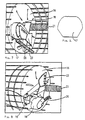
- FIG 1 there is shown a relatively elongated cage 1, formed by bars. It is provided with a first gable wall 2 and a second gable wall 3, which are shown in figures 2 and 3.In the first gable wall 2 there is a circular opening 4. A number of arched recesses 5 are formed in the gable wall with the intention to admit, that the opening 4 is made larger according to the norms of the Bachv ⁇ rdsverk.
- a doublewalled guide 6 is attached to the first gable wall, for guiding vertically of a door 7 in the form of a circular plate.
- a recess 27 is made in the guide 6 at its outside, so that the door may be lifted from its second to its first position.
- An activating means is provided with a cotter pin 8 placed in a corresponding hole in the doublewalled guide 6 and a hole in the door 7 in the activated position of the trap, that is to say when the door 7 is held in a first position.
- the activating means also comprises a thread 9 connected to a first touching means 10 in the form of a treading plate at the floor of the cage.Thus the activating means functions in such a way, that when the animal enters the cage and presses down the treading plate with its weight, the cotter pin 8 is drawn by the thread from its position, so that the door falls down by the gravity and takes its second, deactivated position.
- the treading plate can be ommitted, and the thread can be fastened directly to the floor of the cage.
- the trap is provided with two rectangular surface elements 12 and 13, suitably white, which make the finding of the trap in the dark easier. By providing such surface elements at both sides of the upper portion of the guide 6 the findning is made appreciably easier.
- two holes 14 and 15 are provided in the upper portion, circular in the embodiment shown, but of course other forms may be considered.
- the side of the door, that is turned to these holes is reflecting e g with red colour 14A and fluorescent colour 15A.With this embodiment it is seen by daytime, from the red fluorescent indication in the holes 14 and 15, that the trap is activated, and by night by seeing same by the red reflex, fluorescent, the indication showing that the trap is activated.
- the door is in this case at its other side provided with eg red colour 14B and fluorescent colour 15B. When the door falls down, these fields 14B and 15B getvisible in the direction towards the door 7.
- FIG 1 there is shown a third gable wall 16, provided within the cage in the vicinity of the second gable wall 3.
- This third gable wall 16 forms part of a killing device, and a second opening 17 is provided in the third gable wall, as is more obvious from figures 4 and 5.
- the killing device is shown in activated position in figures 1,4 and 7, and in deactivated position in figures 5 and 8.
- the second opening 17 has the right size to comprise a the head of a catched animal.
- a preferred embodiment of this opening is shown, with side edges, that converge downwardly, so that the jaw of an animal fits, getting fixed in the opening.
- a fixing clamp 18 is provided, fixed to the third gable, being able to take an activated first position as in figures 1,4 and 7 and a deactivated position as in figures 5 and 8.
- the activated position means, that an animal can put in its head through the opening and into the fixing clamp in its activated position, and that its deactivated position means, that the fixing clamp aided by a spring 26 attached to the bottom of the cage, presses the head of the animal against the lower portion of the second opening 17.
- a hit means in the form of hit arm 19 with a preferably conical point 20 is journalled around a horizontal shaft 21, which is mounted in bearings in the second and third gable walls. The hit arm can be pretensioned to an activated position against a screw spring 22.
- the fixing clamp 18 and the hit arm 19 are kept in their activated positions by fixing means, in the form of a plate tongue 24, inserted into one of a number of oval holes 25 in the third gable wall 16.
- This plate tongue is connected to an activating arm 23, which in activated position covers the second opening 17, being able to be acted upon by a relatively small force by a portion of the head of the animal like its lower jaw.
- the function is thus, that the animal by touching the activating arm 23 firstly brings the fixing clamp to lock its head against the lower portion of the opening 17, whereupon the hit arm hits killing against the head of the animal.
- the head of the animal will be fixed in such a position, that the hit arm with its conical portion will hit in the middle of the head of the animal, whereby the killing will be efficient considering the form of the cranium of the animal, in many cases with a ridge in direct connection to the brain.
- the killing device it is of course perfectly possible to form the killing device so that the hit arm will hit from another direction than that shown in the figures, that is to say optionally from above, from below or from a side, but the embodiment shown has proven to be suitable and efficient.
- the spring 26 can also be arranged to give the hit arm a certain starting speed.
Landscapes
- Life Sciences & Earth Sciences (AREA)
- Pest Control & Pesticides (AREA)
- Engineering & Computer Science (AREA)
- Insects & Arthropods (AREA)
- Wood Science & Technology (AREA)
- Zoology (AREA)
- Environmental Sciences (AREA)
- Catching Or Destruction (AREA)
- Medicines That Contain Protein Lipid Enzymes And Other Medicines (AREA)
Claims (7)
- Falle zum Fangen und gegebenenfalls Töten von Tieren wie Nerzen usw., jedoch auch größeren Tieren, mit einem relativ langen Käfig (1), der vorzugsweise mit einem Boden, Seitenwänden und einem Dach aus Stangen gebildet ist, mit einer ersten Giebelwand (2) mit einer vorzugsweise runden ersten Öffnung (4), die einen Eingang für das Tier bildet, sowie einer mit Führungselementen (6) geführten Tür (7), die eine erste Position bei aktivierter Falle, in der die Öffnung (4) offen ist, sowie eine zweite Position, in der die Falle deaktiviert und die Öffnung (4) geschlossen ist, einnehmen kann, ferner mit einem Aktivierungsmittel (8, 9, 10), das auf die Tür (7) einwirken kann, so dass sich diese von der ersten in die zweite Position bewegt, mit einem ersten Berührungselement (10) in dem Käfig, sowie mit einer zweiten Giebelwand (3), wobei die Tür (7) vorzugsweise wie eine runde Platte (7) gebildet ist, die durch an der ersten Giebelwand (2) befestigte Führungselemente (6) geführt wird, und wobei die erste Position der Tür (7) bei aktiviertem Käfig vorzugsweise über ihrer zweiten Position bei deaktiviertem Käfig liegt,
dadurch gekennzeichnet, dass
die Falle mit Anzeigemitteln, die in einer großen Entfernung optisch erkennbar sind, zum Anzeigen der aktivierten bzw. deaktivierten Position der Falle versehen ist, wobei die Anzeigemittel aus mindestens einem Flächenelement (14A, 15A) gebildet sind, das eine erste Position, in der es durch ein Loch (14, 15) in dem Führungselement (6) aus einer ersten Richtung relativ zu der Falle von außen sichtbar ist, bzw. eine zweite Position einnehmen kann, in der es aus der ersten Richtung nicht durch das Loch (14, 15) sichtbar ist, wenn die Tür (7) ihre erste oder zweite Position einnimmt. - Falle nach Anspruch 1,
dadurch gekennzeichnet, dass die Anzeigemittel mindestens ein weiteres Flächenelement (14B, 15B) aufweisen, das eine Position, die außerhalb von der ersten Giebelwand (2) aus einer zweiten Richtung gegenüber der ersten Richtung sichtbar ist, bzw. eine Position einnehmen kann, die nicht sichtbar ist, wenn die Tür (7) ihre erste oder zweite Position einnimmt. - Falle nach Anspruch 1 oder 2,
dadurch gekennzeichnet, dass sie mindestens ein drittes Flächenelement (12, 13) mit einer solchen Form aufweist, dass es optisch in einfacher Weise von den ersten (14A, 15A) bzw. zweiten (14B, 15B) Flächenelementen unterscheidbar ist, um eine Bestimmung der Position der Falle im Dunkeln zu erleichtern. - Falle nach einem der Ansprüche 1 bis 3,
dadurch gekennzeichnet, dass mindestens eines der Flächenelemente (14A, 15A, 14B, 15B, 12, 13) reflektierend und/oder fluoreszierend ist. - Falle nach einem der vorhergehenden Ansprüche, bei der die Aktivierungsmittel ein erstes Berührungselement in Form einer Tretplatte (10) umfassen, die am Boden des Käfigs gelagert ist, dadurch gekennzeichnet, dass
die Tretplatte (10) über einen Faden (9) mit einem Splint (8) verbunden ist, der die Tür (7) in ihrer ersten Position hält, wobei der Aktivierungsdruck an der Tretplatte (10) durch Verändern des Winkels zwischen den Schenkeln des Splints (8) einstellbar ist. - Falle nach einem der vorhergehenden Ansprüche,
dadurch gekennzeichnet, dass sie mit einer Tötungseinrichtung in dem Teil des Käfigs, der der Öffnung (4) gegenüberliegt, versehen ist, mit einer dritten inneren Giebelwand (16), in der sich eine zweite, so bemessene Öffnung (17) befindet, dass sie den Kopf eines Tieres mit einem bestimmten Rand aufnehmen kann, ferner mit einer fixierenden Klemmeinrichtung (8), die eine erste aktivierte Position mit einem aktiven Teil in einem solchen Abstand von dem Rand der Öffnung (17), dass Raum für den Kopf eines Tieres in der fixierenden Klemmeinrichtung (18) vorhanden ist, und eine zweite deaktivierte Position einnehmen kann, in der der aktive Teil mit einer bestimmten Kraft, die zum Beispiel durch eine Feder (26) erzeugt wird, wirkt, so dass der Kopf eines Tieres gegen den Rand der Öffnung (17) fixiert wird, sowie mit einer Schlageinrichtung (19), die eine aktivierte erste, gegen eine Krafteinrichtung wie eine Schraubenfeder (22) vorgespannte Position und eine deaktivierte zweite Position innerhalb des Höhenbereiches der zweiten Öffnung (17) einnehmen kann, so dass die Schlageinrichtung (19) gegen den Kopf eines Tieres schlagen und dieses töten kann, wenn es durch die fixierende Klemmeinrichtung (18) fixiert worden ist, wobei die fixierende Klemmeinrichtung und die Schlageinrichtung (19) aus ihren ersten Positionen, in denen sie durch die fixierenden Einrichtungen (24, 25) fixiert sind, durch eine zweite Berührungseinrichtung (23), die in dem Bereich der zweiten Öffnung (17) liegt, gelöst werden können, auf die eine relativ kleine, mit einem Teil des Kopfes eines Tieres wie seiner unteren Backe ausgeübte Kraft einwirken kann. - Falle nach Anspruch 6, dadurch gekennzeichnet, dass die Öffnung (17) mit Seitenkanten ausgebildet ist, die in einer Richtung nach unten zusammenlaufen.
Applications Claiming Priority (3)
| Application Number | Priority Date | Filing Date | Title |
|---|---|---|---|
| SE9303200 | 1993-10-01 | ||
| SE9303200A SE506081C2 (sv) | 1993-10-01 | 1993-10-01 | Djurfälla försedd med indikeringsorgan för indikering av fällans gillrade respektive avgillrade läge |
| PCT/SE1994/000903 WO1995009531A1 (en) | 1993-10-01 | 1994-09-30 | A trap for trapping and possibly killing of animals, especially small ones |
Publications (2)
| Publication Number | Publication Date |
|---|---|
| EP0731633A1 EP0731633A1 (de) | 1996-09-18 |
| EP0731633B1 true EP0731633B1 (de) | 2002-06-12 |
Family
ID=20391275
Family Applications (1)
| Application Number | Title | Priority Date | Filing Date |
|---|---|---|---|
| EP94929083A Expired - Lifetime EP0731633B1 (de) | 1993-10-01 | 1994-09-30 | Falle zum fangen und gegebenenfalls abtöten von tieren, insbesondere kleintieren |
Country Status (8)
| Country | Link |
|---|---|
| US (1) | US6003265A (de) |
| EP (1) | EP0731633B1 (de) |
| AT (1) | ATE218801T1 (de) |
| AU (1) | AU7826894A (de) |
| CA (1) | CA2172612A1 (de) |
| DE (1) | DE69430814D1 (de) |
| SE (1) | SE506081C2 (de) |
| WO (1) | WO1995009531A1 (de) |
Families Citing this family (10)
| Publication number | Priority date | Publication date | Assignee | Title |
|---|---|---|---|---|
| US6202340B1 (en) * | 1999-08-18 | 2001-03-20 | Joniel Nieves | Electronically actuated animal trap |
| US20060042153A1 (en) * | 2001-02-26 | 2006-03-02 | Bowerman Stephen H | Animal trap |
| US20050097808A1 (en) * | 2003-09-12 | 2005-05-12 | Vorhies James F. | Humane tubular trap, remote trap monitoring system and method and programs for monitoring multiple traps |
| GB0325446D0 (en) * | 2003-10-31 | 2003-12-03 | Reckitt Benckiser Au Pty Ltd | Mousetrap |
| US8061076B2 (en) * | 2008-05-28 | 2011-11-22 | Kelley Harry R | Portable large animal trap and method |
| US7607254B1 (en) * | 2008-05-30 | 2009-10-27 | Chang-Hsiu Huang | Mouse trap having a triggering plate |
| US7854088B2 (en) * | 2008-09-12 | 2010-12-21 | Kurachi Steve T | Animal trap |
| US8112934B2 (en) * | 2009-11-24 | 2012-02-14 | Alter Enterprise Llc | Bear trap |
| US8418396B2 (en) * | 2009-12-10 | 2013-04-16 | Frank Moustirats | Humane animal trap |
| US11523603B2 (en) * | 2020-05-21 | 2022-12-13 | Elmer Para | Animal live trap assembly |
Family Cites Families (8)
| Publication number | Priority date | Publication date | Assignee | Title |
|---|---|---|---|---|
| DE126038C (de) * | ||||
| US1654434A (en) * | 1926-12-27 | 1927-12-27 | Senecal Aaron Townsend | Door-controlling device for traps |
| DE593752C (de) * | 1931-04-28 | 1934-03-03 | Friedrich Dietsch | Kastenfalle |
| US4144667A (en) * | 1977-07-11 | 1979-03-20 | Woodstream Corporation | Self-locking disposable rodent trap |
| US4310984A (en) * | 1980-04-03 | 1982-01-19 | Brubaker Jr Fred A | Rodent and animal trap |
| US4393616A (en) * | 1981-03-23 | 1983-07-19 | Critter Getter, Inc. | Trap apparatus, and methods of fabricating and utilizing same |
| US4607450A (en) * | 1984-11-20 | 1986-08-26 | Amcan, Inc. | Enclosed mousetrap having improved trap mechanism |
| KR0141362B1 (ko) * | 1989-04-27 | 1998-06-01 | 몰톤 피터 | 낚시용 미끼 |
-
1993
- 1993-10-01 SE SE9303200A patent/SE506081C2/sv unknown
-
1994
- 1994-09-30 AU AU78268/94A patent/AU7826894A/en not_active Abandoned
- 1994-09-30 US US08/619,516 patent/US6003265A/en not_active Expired - Fee Related
- 1994-09-30 DE DE69430814T patent/DE69430814D1/de not_active Expired - Lifetime
- 1994-09-30 EP EP94929083A patent/EP0731633B1/de not_active Expired - Lifetime
- 1994-09-30 AT AT94929083T patent/ATE218801T1/de not_active IP Right Cessation
- 1994-09-30 CA CA002172612A patent/CA2172612A1/en not_active Abandoned
- 1994-09-30 WO PCT/SE1994/000903 patent/WO1995009531A1/en not_active Ceased
Also Published As
| Publication number | Publication date |
|---|---|
| EP0731633A1 (de) | 1996-09-18 |
| ATE218801T1 (de) | 2002-06-15 |
| CA2172612A1 (en) | 1995-04-13 |
| SE9303200D0 (sv) | 1993-10-01 |
| SE9303200L (sv) | 1995-04-24 |
| US6003265A (en) | 1999-12-21 |
| DE69430814D1 (de) | 2002-07-18 |
| SE506081C2 (sv) | 1997-11-10 |
| AU7826894A (en) | 1995-05-01 |
| WO1995009531A1 (en) | 1995-04-13 |
Similar Documents
| Publication | Publication Date | Title |
|---|---|---|
| US4144667A (en) | Self-locking disposable rodent trap | |
| US6088948A (en) | Method and a device for trapping rats, mice and the like | |
| US4899484A (en) | Humane animal trap | |
| US4578892A (en) | Rodent trap | |
| EP0731633A1 (de) | Falle zum fangen und gegebenenfalls abtöten von tieren, insbesondere kleintieren | |
| US5148625A (en) | Roach trap | |
| US20110289821A1 (en) | Humane racoon restraint | |
| KR19990028200A (ko) | 작은 동물의 포획 및 살상용 트랩 | |
| US4682441A (en) | Animal trap | |
| KR20190029201A (ko) | 쥐 포획용 트랩 | |
| NL8502887A (nl) | Knaagdierenval. | |
| US1996872A (en) | Animal trap | |
| US5564221A (en) | Animal trap entrance device | |
| JPS6235336Y2 (de) | ||
| DE3436330C1 (de) | Vorrichtung zum Fangen von Tieren | |
| EP0910947B1 (de) | Verbesserte ökologische Käfigfalle | |
| AU603110B2 (en) | Trap | |
| KR102284410B1 (ko) | 쥐 포획 장치 | |
| US2252908A (en) | Mousetrap | |
| RU2073434C1 (ru) | Мышеловка | |
| JP2023037663A (ja) | 害獣捕獲装置および複数害獣捕獲装置 | |
| US1948199A (en) | Animal trap | |
| JPS64782Y2 (de) | ||
| JP3060803U (ja) | 動物捕獲装置 | |
| TW202011809A (zh) | 具提醒功能的誘蟲裝置 |
Legal Events
| Date | Code | Title | Description |
|---|---|---|---|
| PUAI | Public reference made under article 153(3) epc to a published international application that has entered the european phase |
Free format text: ORIGINAL CODE: 0009012 |
|
| 17P | Request for examination filed |
Effective date: 19960517 |
|
| AK | Designated contracting states |
Kind code of ref document: A1 Designated state(s): AT CH DE ES GB IT LI NL PT SE |
|
| 17Q | First examination report despatched |
Effective date: 19981113 |
|
| GRAG | Despatch of communication of intention to grant |
Free format text: ORIGINAL CODE: EPIDOS AGRA |
|
| GRAG | Despatch of communication of intention to grant |
Free format text: ORIGINAL CODE: EPIDOS AGRA |
|
| GRAH | Despatch of communication of intention to grant a patent |
Free format text: ORIGINAL CODE: EPIDOS IGRA |
|
| GRAH | Despatch of communication of intention to grant a patent |
Free format text: ORIGINAL CODE: EPIDOS IGRA |
|
| GRAA | (expected) grant |
Free format text: ORIGINAL CODE: 0009210 |
|
| AK | Designated contracting states |
Kind code of ref document: B1 Designated state(s): AT CH DE ES GB IT LI NL PT SE |
|
| PG25 | Lapsed in a contracting state [announced via postgrant information from national office to epo] |
Ref country code: NL Free format text: LAPSE BECAUSE OF FAILURE TO SUBMIT A TRANSLATION OF THE DESCRIPTION OR TO PAY THE FEE WITHIN THE PRESCRIBED TIME-LIMIT Effective date: 20020612 Ref country code: LI Free format text: LAPSE BECAUSE OF FAILURE TO SUBMIT A TRANSLATION OF THE DESCRIPTION OR TO PAY THE FEE WITHIN THE PRESCRIBED TIME-LIMIT Effective date: 20020612 Ref country code: IT Free format text: LAPSE BECAUSE OF FAILURE TO SUBMIT A TRANSLATION OF THE DESCRIPTION OR TO PAY THE FEE WITHIN THE PRESCRIBED TIME-LIMIT;WARNING: LAPSES OF ITALIAN PATENTS WITH EFFECTIVE DATE BEFORE 2007 MAY HAVE OCCURRED AT ANY TIME BEFORE 2007. THE CORRECT EFFECTIVE DATE MAY BE DIFFERENT FROM THE ONE RECORDED. Effective date: 20020612 Ref country code: CH Free format text: LAPSE BECAUSE OF FAILURE TO SUBMIT A TRANSLATION OF THE DESCRIPTION OR TO PAY THE FEE WITHIN THE PRESCRIBED TIME-LIMIT Effective date: 20020612 Ref country code: AT Free format text: LAPSE BECAUSE OF FAILURE TO SUBMIT A TRANSLATION OF THE DESCRIPTION OR TO PAY THE FEE WITHIN THE PRESCRIBED TIME-LIMIT Effective date: 20020612 |
|
| REF | Corresponds to: |
Ref document number: 218801 Country of ref document: AT Date of ref document: 20020615 Kind code of ref document: T |
|
| REG | Reference to a national code |
Ref country code: GB Ref legal event code: FG4D |
|
| REG | Reference to a national code |
Ref country code: CH Ref legal event code: EP |
|
| REF | Corresponds to: |
Ref document number: 69430814 Country of ref document: DE Date of ref document: 20020718 |
|
| PG25 | Lapsed in a contracting state [announced via postgrant information from national office to epo] |
Ref country code: SE Free format text: LAPSE BECAUSE OF FAILURE TO SUBMIT A TRANSLATION OF THE DESCRIPTION OR TO PAY THE FEE WITHIN THE PRESCRIBED TIME-LIMIT Effective date: 20020912 Ref country code: PT Free format text: LAPSE BECAUSE OF FAILURE TO SUBMIT A TRANSLATION OF THE DESCRIPTION OR TO PAY THE FEE WITHIN THE PRESCRIBED TIME-LIMIT Effective date: 20020912 |
|
| PG25 | Lapsed in a contracting state [announced via postgrant information from national office to epo] |
Ref country code: DE Free format text: LAPSE BECAUSE OF FAILURE TO SUBMIT A TRANSLATION OF THE DESCRIPTION OR TO PAY THE FEE WITHIN THE PRESCRIBED TIME-LIMIT Effective date: 20020913 |
|
| PGFP | Annual fee paid to national office [announced via postgrant information from national office to epo] |
Ref country code: GB Payment date: 20021002 Year of fee payment: 9 |
|
| NLV1 | Nl: lapsed or annulled due to failure to fulfill the requirements of art. 29p and 29m of the patents act | ||
| PG25 | Lapsed in a contracting state [announced via postgrant information from national office to epo] |
Ref country code: ES Free format text: LAPSE BECAUSE OF FAILURE TO SUBMIT A TRANSLATION OF THE DESCRIPTION OR TO PAY THE FEE WITHIN THE PRESCRIBED TIME-LIMIT Effective date: 20021220 |
|
| REG | Reference to a national code |
Ref country code: CH Ref legal event code: PL |
|
| PLBE | No opposition filed within time limit |
Free format text: ORIGINAL CODE: 0009261 |
|
| STAA | Information on the status of an ep patent application or granted ep patent |
Free format text: STATUS: NO OPPOSITION FILED WITHIN TIME LIMIT |
|
| 26N | No opposition filed |
Effective date: 20030313 |
|
| PG25 | Lapsed in a contracting state [announced via postgrant information from national office to epo] |
Ref country code: GB Free format text: LAPSE BECAUSE OF NON-PAYMENT OF DUE FEES Effective date: 20030930 |
|
| GBPC | Gb: european patent ceased through non-payment of renewal fee |
Effective date: 20030930 |