EP0730932B1 - Belt tensioner - Google Patents
Belt tensioner Download PDFInfo
- Publication number
- EP0730932B1 EP0730932B1 EP96103026A EP96103026A EP0730932B1 EP 0730932 B1 EP0730932 B1 EP 0730932B1 EP 96103026 A EP96103026 A EP 96103026A EP 96103026 A EP96103026 A EP 96103026A EP 0730932 B1 EP0730932 B1 EP 0730932B1
- Authority
- EP
- European Patent Office
- Prior art keywords
- strap
- loop
- clamping device
- clamping
- spindle
- Prior art date
- Legal status (The legal status is an assumption and is not a legal conclusion. Google has not performed a legal analysis and makes no representation as to the accuracy of the status listed.)
- Expired - Lifetime
Links
Images


Classifications
-
- B—PERFORMING OPERATIONS; TRANSPORTING
- B25—HAND TOOLS; PORTABLE POWER-DRIVEN TOOLS; MANIPULATORS
- B25B—TOOLS OR BENCH DEVICES NOT OTHERWISE PROVIDED FOR, FOR FASTENING, CONNECTING, DISENGAGING OR HOLDING
- B25B1/00—Vices
- B25B1/20—Vices for clamping work of special profile, e.g. pipes
- B25B1/205—Vices of the chain or strip type
-
- B—PERFORMING OPERATIONS; TRANSPORTING
- B25—HAND TOOLS; PORTABLE POWER-DRIVEN TOOLS; MANIPULATORS
- B25B—TOOLS OR BENCH DEVICES NOT OTHERWISE PROVIDED FOR, FOR FASTENING, CONNECTING, DISENGAGING OR HOLDING
- B25B5/00—Clamps
- B25B5/14—Clamps for work of special profile
-
- B—PERFORMING OPERATIONS; TRANSPORTING
- B25—HAND TOOLS; PORTABLE POWER-DRIVEN TOOLS; MANIPULATORS
- B25B—TOOLS OR BENCH DEVICES NOT OTHERWISE PROVIDED FOR, FOR FASTENING, CONNECTING, DISENGAGING OR HOLDING
- B25B5/00—Clamps
- B25B5/14—Clamps for work of special profile
- B25B5/142—Clamps for work of special profile for windows and frames
Definitions
- the invention relates to a strap tensioner with a strap, which is used to wrap one or more workpieces forms an outer loop with a tensioning device, relative to which a first end of the loop can be fixed, by means of which is the outer loop for clamping the workpiece or of the workpieces is contractible and which one on the Loop with a loop element supported base element as well as a tension element, with an adjusting device, by means of which the tension element and the basic element are movable relative to each other, with a relative movement the outer loop of the basic element and tension element is contractible under the action of a pulley.
- Such a belt tensioner according to the preamble of independent claim 1 is known from US 3,584,860 and is used for reclamping workpieces of various types Forms, whereby a tensioning of the tape according to the principle of a simple pulley.
- the tensioning device is designed so that it pulls on both ends of the outer loop, which as Tension tape used textile tape when tensioning on two rollers is wound up.
- this solution has the disadvantage that due to the different circumferential dimensions when winding uneven pulling of the tension band on the rollers on both sides of the outer loop.
- a position serves for free pulling out of the tensioning strap, one for quick Winding up the strap and a third position for Tension the strap in small rest positions.
- Such belt tensioners are particularly suitable for holding together bulky parts or parts with interrupted peripheral surfaces, such as B. backrests or feet.
- To the misshapen parts also include pillars, kidney-shaped furniture or oval-round workpieces.
- normal frames can also be used Square, hexagonal or octagonal shape.
- Belt tensioners come in a wide variety of designs known.
- belt tensioners are known, in which a Lashing strap with ratchet is used.
- Other embodiments of tape tensioners use a spindle with Spindle nut for operating the tape guide. With these Solutions are required, however, the two hinge sides or tape ends, holding the Band depends on how good the clamping is.
- the invention is therefore based on the object Belt tensioner of the generic type to improve such that this can be handled as advantageously as possible.
- the belt tensioner according to the invention is simple can be actuated because only to pull the outer loop together a relative movement between the basic element and tension element can be carried out by means of the adjusting device.
- the size the sling can be varied to fit different
- the size of the loop is provided with a fixing device, with which the two ends can be fixed in the clamping device are.
- a particularly advantageous embodiment due to its simplicity provides that the noose with a first Place on the basic element and with at least two more Places on the traction element is attacking.
- the loop is two Loops forms, the bends the two other places form with which the loop abuts the tension element. With these two loops the is easy Effect of the double pulley can be represented, preferably one end of each loop at each end The loop lies and at the other end of the loop the strap continues to the outer loop.
- a particularly simple embodiment of the invention Belt tensioners provide that a first end of the Loop arranged at a fixed point on the strap is and that the strap is over a second end the noose continues as a strap reserve and that the size of the sling by reducing or enlarging the Tension strap reserve is variable, the size of the sling by exact positioning of the first end relative to the second end is definable.
- first and second ends of the loop could be arranged on a separate locking device which is used to vary the size of the sling.
- the first end in the jig prefferably be determined independently of the fixing device.
- a particularly useful solution provides that the first end and the second end in the fixing device of the Clamping device can be fixed so that the tensile force on one End of the noose immediately to the other end of the Noose works.
- both first end as well as the second end of the noose in the Fixing device can be fixed, since then the fixing device affects both ends and, for example, both ends presses against each other, which is particularly the case with one braided or textile strap due to the high surface friction leads to the fact that in the fixing device both ends immediately due to the friction between them are fixed relative to each other.
- the fixing device can be of various types and Be done wisely.
- An advantageous embodiment of the Fixing device provides that this is a fixing element and has an abutment between which the strap can be clamped is.
- the strap between the fixing element and the abutment can in principle be a separate actuating device, for example, provided with a toggle mechanism his.
- a particularly easy to use solution provides that the fixing device and the adjusting device at the same time, in particular by means of the same actuating element, can be operated, so that in addition to easy handling it is also ensured that when actuating the adjusting device for tensioning the strap Fixing device in the sense of defining at least one End of the loop is actuated.
- a particularly advantageous embodiment of the invention Solution provides that the fixing element when moving the base element and the tension element relative can be actuated relative to one another by the adjusting device.
- the adjusting device via the fixing device on the base element supports and thus the fixing device at least that second end of the loop and possibly also the first Fixed end relative to the basic element.
- the Tension element has two tensile bodies, one of which each in one of the at least two other places on the Noose works.
- the tension members are preferably on both sides of the adjusting device arranged on the tension element.
- Such a spindle has the advantage that it is easier Operability is able to a relatively large distances generate high power, which is particularly the case here Case in which the relative movement between the tension element and Basic element of a double pulley system on the outside Has noose that matters.
- the Spindle with one spindle end on the fixing element of the Fixing device supports.
- Relatively rotatably relative to the tension element carrying the spindle nut leading to the adjusting spindle is preferably provided that the tension element is connected to the base element Linear guide in the direction of this and away from it movable, but is non-rotatably guided.
- This linear guide could be of various types and Be trained.
- An advantageous training of Linear guide provides that this part of a housing, preferably formed by walls of the same, on which in particular the basic element is held.
- the basic element Part preferably a bottom part, of the housing forms.
- the guide openings are preferably laid in such a way that that the respective run of the sling after the each loop formed between the base element and tension element extends through the respective guide opening.
- the tensioning device a carrier for the strap reserve has, on which in particular the strap reserve can be filed in an orderly manner.
- This carrier is preferably used as a winding body for the Strap reserve formed, on which thus the Can wind up the strap reserve in an orderly manner.
- the winding body could on the one hand through the housing itself be formed so that the strap reserve is easy can wind the winding body formed by the housing.
- the winding body is a forms rotatable coil relative to the housing on which the Tension band reserve can be wound up in the form of a wrap.
- the spool is preferably with a crank for winding of the strap reserve rotatable.
- corner elements could, for example, be used for the workpieces wrapping the outer loop freely between Strap and the respective workpieces can be inserted.
- This has the disadvantage, however, that it is easy to use of the belt tensioner according to the invention is no longer possible.
- corner elements are captively fixable on the strap.
- the corner elements are preferably used for fixing to the strap provided with holding elements acting on the strap, who are trained in a variety of ways could be.
- a particularly advantageous embodiment provides that the holding elements are designed so that the strap is transverse to its longitudinal direction in one through the holding elements fixed position on the corner elements can be inserted, so that there is no need to close the outer loop open and for example the strap through this lead through all around.
- the holding elements are preferably designed so that the strap from one side edge to a flat side spread.
- the securing element can be a nose which the tensioning strap lies on with the side edge which is not overlapped by the holding element.
- the securing element also represents a holding element and thus the two holding elements of mutually opposite side edges starting from the tensioning strap.
- the corner elements can be used in many different ways be trained.
- the corner elements have a cavity Grasp in a U-shape and end of the leg of the U Have pressure lugs with which the corner elements on the Workpieces work.
- the corner elements are included so that it can be placed on the corners of workpieces so that the pressure lugs rest on opposite sides of the corners.
- the corner elements can be designed so that they with their pressure noses act directly on the workpiece. Yet however, it is more advantageous if the corner elements in the area their pressure lugs with pivoted on these pressure parts are provided, which in turn have printing areas, with which the printed parts act on the workpiece.
- the printed parts are flat or slightly curved printing surfaces.
- corner elements are designed so that the tensioning band across the full length of the latter rests in order to achieve the best possible pressure effect.
- corner elements are also preferably so trained that the pressure tabs symmetrical to a center line of the strap are arranged.
- the pressure parts are preferably designed such that it is symmetrical to a central plane of the Stretch strap.
- a particularly advantageous embodiment of the invention Band tensioner provides that this for the Clamping workpieces of symmetrical and shapeless Shape with textile tape and several instep areas to be underlaid to protect the workpieces and for better sliding of the Tensioning strap along this when tensioning by means of a usual clamping element within a clamping device or a Tensioning device is formed, the tensioning strap inside of the tensioning device or the tensioning device in tensioning channels of deflection corners - or also called tensile elements - is performed so that the effect of a double Pulley results and preferably with a tensioning Spindle between a pressure plate and the two sides of the strap are clamped to the surrounding housing become.
- Another advantageous variant of the invention Solution provides that two through openings in the housing are present on the workpiece exit side, through which the band on a radius when tensioning inwards is pulled.
- tape guide Has band channels for redirecting to the depth of the bandwidth and to facilitate marking when necessary firmly manufactured preferably as an injection molded part made of plastic Part are attached to the open side.
- Cams are preferably attached to the housing for winding serve the tape when storing the tensioning device, and a slot to secure the tape.
- tensioning device or the tensioning device additionally with two or more corner elements or corners to protect the Workpiece edges is equipped and for better sliding of the Tension band around these edges, these for edges or Miter angles from 45 to 120 ° can be used continuously and captive on the strap afterwards are mountable.
- the clamping corner or the corner element is preferably in one piece made from an open cylindrical shape, the Opening is set so that acute angles and obtuse angles have space in the inner cavity of the hollow cylinder.
- the tape guide in a slot that is open at the top and after has an approach at the bottom and an introductory slope at the top and a cam on both sides.
- This cam is expediently formed on the cylinder and has an insertion bevel with a barb functioning Approach to tape backup.
- the approach lies thereby deeper than the slot drain.
- An advantageous embodiment of an inventive Belt tensioner creates the possibility with the simplest ease of use quickly after gripping the workpiece to high Resilience to come.
- the belt tensioner is a compact device with and output trained.
- the belt tensioner is also preferably equipped with Protective or clamping corners for the most common miter angles.
- the tensioning strap When tensioning, the tensioning strap should be drawn in evenly on both sides become.
- the span corners should be stepless for miter angles or spanned corners from 45 to 120 ° can be used can adapt to the manufactured angle and easily resilient. They should be attached to the tape as required can without being unwound or unwound need to quickly switch to clamping with or without Span corners. They should also be captive on the strap hold tight. For storage, it is advantageous that Being able to wind up the strap and the protective corners cannot be lost to attach to the jig.
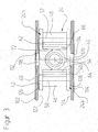
- a belt tensioner shown as a whole in FIG. 1 comprises one from a tension band 10, preferably a textile band, formed outer loop 12a, which for example two Workpieces 14 and 16 encirclingly wrap around on the outside and to a clamping device designated as a whole by 20 is guided, which serves the outer loop 12a contract.
- the clamping device 20 comprises a housing 22, in which as shown in Fig. 2, a tension element 24 is arranged, by means of an adjusting device designated as a whole by 26 relative to a basic element designated 28, which forms a base of the housing 22 and which has two loop bushings 30 and 32, through which the Tension strap 10 from the outer loop 12a into an interior of the Housing 22 is guided.
- the outer loop 12a is provided with a lock Z with interconnectable and detachable lock elements Z 1 and Z 2 , which makes it possible to open the outer loop 12a in order to be able to put the outer loop 12a around the workpieces 14 and 16 without being able to these have to be pushed through the side of the loop.
- the lock Z creates the possibility, in the event that a particularly large outer loop 12a is required, to open the lock Z and to insert an extension piece between the lock parts Z 1 and Z 2 , which is connected at both ends to the lock part Z 1 or Z 2 has connectable lock parts.
- the tension element 24 comprises, as shown in FIGS. 2 and 3, two side walls 40 and 42 running parallel to one another, between which there is a spindle nut 44 and between which also on both sides of the spindle nut 44 and preferably pull rollers 46 and 48 lying symmetrically to the latter extend, each rotatable on the side walls 42 and 44 are mounted so that their axes of rotation 50 and 52 are preferably parallel and in a perpendicular to an axis 54 of the spindle nut 44 lying level 56.
- the entire tension element 24 is preferably composed of two parts 24a and 24b, the part 24a being the side cheek 40 and storage for the pull rollers 46 and 48 and the Guide rollers 60 and 62 includes which are integral with this are molded. Furthermore, the cheek 40 is also the Spindle nut 44 formed in one piece.
- the second part 24b preferably includes the side cheek 42 as well as receptacles for the bearings of the pull rollers 46 and 48 and the guide rollers 60 and 62 and one on the spindle nut 44 adjacent and additionally stabilizing support element 72.
- the two parts 24a and 24b are through Common securing elements connected together.
- the loop 12 goes out from a first fixable in a fixing device 80 End 82 and forms after the first end with one first loop center 12e one from the fixing device 80 outgoing, U-shaped loop wrapping around the pulling roller 46 84, following which the run 12e through the Loop feedthrough 30 in the form of a curved feedthrough slot through the base element 18 from the housing 22 emerges in order to then the outside of the clamping device 20th to form lying outer loop 12a.
- the tensioning strap 10 also extends over the first end 82 the loop 12 and forms an end piece 86, which the base element 28 fixed by means of a holding pin 88 is, wherein the holding pin 88 is formed by the end piece 86 Passes through eyelet 90.
- a second strand extends 12z of the loop 12 also in the form of a U-shaped Loop 94 over the pull roller 48 to then also through the loop passage 32 in the form of a curved slot in the base element 28 and emerge from the housing 22 to the outside of the jig To form 20 lying outer loop 12a.
- the second end 92 extends Sling 12 the tension band 10 over the fixing device 80 out and forms a strap reserve 96, which over the circumferential surface 64 of the guide roller facing the spindle nut 44 60 of the tension element 24 is guided and in the connection to the guide roller 60 on a spool 98 in the form of a Winding 100 can be wound.
- the coil 98 is, as shown in FIG. 4, between two Side walls 102 and 104 of the housing 22 are arranged and by means of one penetrating the side walls 102 and 104 Shaft 106 rotatably supported about an axis 108. On one side a crank 110 is rotatably connected to the shaft 106, with which the tension band reserve 96 in the form of the winding 100 the coil 98 can be wound up.
- the side walls 102 and 104 also provided with longitudinal slots 112 and 114, in which the pulling element 24 relative in an adjustment direction 116 is movably guided to the base element 28, the tension element 24 in the longitudinal slots 112 and 114 with projections 118 or 120 engages. Furthermore, that is Tension element 24 on inner sides 122 and 124 of the side walls 102 and 104 with outer sides 126 and 128 respectively and is thereby additionally non-rotatable, but in the direction of adjustment 116 slidably guided.
- the longitudinal slots 112 and 114 run parallel to the Adjustment direction 116.
- the movement of the tension element 24 relative to the base element 28 provided adjusting device 26 comprises a spindle 130, which passes through the spindle nut 44 and with her Spindle end 132 engages in a pressure piece 134, which in addition is still provided with a fixing shoe 136.
- Thrust piece 134 is preferably used as a clamp usual clamping spindle equipped with a usual pressure piece 134, with the spindle 130 also by a Clamping clamps usual spindle handle 138 is rotatable.
- the fixing shoe placed on the pressure piece 134 forms together with an abutment arranged on the base element 28 140 the fixing device 80, in which the first end 82 and the second end 92 of the loop 12 can be fixed.
- the Fixation takes place in that the two ends 82 and 92 of the Loop 12 between the abutment 140 and the fixing shoe 136 then be clamped when the spindle 130 through Turning the spindle handle 138 is rotated so that the Traction element 24 moves away from the base element 28 and thus the on the loops 84 and 94 in the sense of enlarging them acting pull rollers 46 and 48 ultimately lead that both over the first run 12e and the second run 12z the strap of the outer loop 12a through the Loop bushings 30 and 32 in the housing 22 below Reduction of the outer loop 12a is drawn.
- the spindle 130 must over the pressure piece 134 and ultimately support the fixing shoe 136 on the base element 28, this over the between the fixing shoe 136 and the abutment 140 clamped ends 82 and 92 of the loop 12 takes place, so that ultimately the support of the spindle 130th via the fixing device 80 on the base element 28 and thereby simultaneously the ends 82 and 92 of the loop fixed relative to the base element 28.
- the outer loop lying outside the tensioning device 20 12a either with or without corner elements to be explained 140 placed around the workpieces 14 and 16 and by winding the tension band reserve 96 on the spool 98 with the adjusting device released 26 the outer loop 12a contracted so far, that either this directly or via the corner elements the workpieces 14, 16 abut against them.
- the spindle handle 180 is rotated so that by action the spindle 130, the tension element 24 is different from the base element 28 moved away, the spindle end 132 is inevitably supported via the pressure piece 134 and the fixing shoe 136 on the Abutment 140 from, so that by the fixing shoe 136 and the abutment 140 formed fixing device 80 the ends 82 and 92 of the slings fixed by clamping and now by the movement of the tension element 24 conditional enlargement of the loops 84 and 94 in the sense of a Reduction of the outside of the clamping device 20 outer loop 12a, so that thereby the workpieces 14 and 16 are clamped together.
- Corner elements 140 Targeted around the workpieces 14, 16, preferably in the area their corners with a starting from the outer loop 12a To be able to apply clamping force are preferred Corner elements 140 in the context of the belt tensioner according to the invention applicable.
- each of these corner elements comprises 140 a base body 142 which has two pressure lugs 144 and 146, between which there is a cavity 148, the the one that extends to the pressure tabs 144 and 146
- Basic body 142 encompasses a U-shaped cross section.
- the cavity 148 serves to corner one of the workpieces 14 or 16 to record, with the base body 142 on both sides the corner on the workpiece.
- the base body 142 can directly with the Support pressure tabs 144 and 146, provided this does not result in a superficial Workpieces 14 or 16 are damaged.
- the pressure lugs 144 and 146 are still provided with pressure parts 148, 150 which, as in 6 and 7, have flat pressure surfaces 152, with which the pressure parts 148 and 150 on the surface of the respective workpiece 14, 16 can be placed.
- the printing areas 152 form the surface of a pressure plate 154, of their opposite narrow sides on one of the Pressure surface 152 opposite side of the pressure plate 154 Stand bearing plates 156 and 158, with which the pressure parts 148 on the pressure lugs 144 or 146 can be pivoted about an axis 160 are stored.
- the bearing plates 156 and 158 preferably have Bores 162 in which one at each opposite Outer sides 164, 166 of the pressure lugs arranged cylindrical projection 168 and 170 engages and thereby Pivots for the pressure parts 148 forms.
- the base body 142 has in the direction of the pivot axis 160 and thus also in the longitudinal direction of the pressure surface 152 Expansion, which is a secure support of the strap 10 guaranteed with its entire width transverse to its longitudinal direction.
- the base body 142 on its side opposite the cavity 148 a preferably curved support surface 180 for the Tensioning strap 10, wherein on both sides of the support surface 180 from Base body 142 rising over the bearing surface 180 Side webs 182 and 184 are formed, between which the Tensioning strap 10 is guided lying on the bearing surface 180 and which a lateral sliding of the strap over prevent the bearing surface 180.
- Tension band 10 extends from each of the side webs 182 and 184 approximately up to a centerline 186 of the support surface 180, which is also a centerline of the one lying on this Tension band 10 represents reaching and in the longitudinal direction of the tension band 10 are spaced apart projections 188 and 190 which support surface 180 at a distance of this overlap and a space 192 or 194 leave between themselves and the bearing surface 180 so that the strap 10 can be pulled through this space is.
- the strap 10 is not only on both sides of the Support surface 180 through the side webs 182 and 184 instead also opposite the bearing surface 180 through the projections 188 and 190 so fixable on the base body 142 that the tensioning strap 10 does not pass over the base body 142 by itself can slide away, so that the base body 142 is also loose Tension strap is guided in the same longitudinal direction, since the projections 188 and 190 a complete detachment from the contact surface Prevent 180.
- the base body 142 is preferably formed by two halves 142a and 142b, which are identical and in one another along a plane running along the center line 186 fit and are fixed relative to each other.
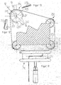
- FIGS. 9 to 15 comprises the one labeled 210 in FIG. 9
- Tensioning device a tape guide 212 - which the tension element represents - a housing 214, a clamping spindle 216 with a Pressure plate 218 and a spindle handle 220.
- the strap 222 is - for example, with its outer Noose - shown exposed around two workpieces 224 and 226.
- the strap When pulling the strap in the direction of arrow 223 in the simplest case, the strap is directly attached to the Workpieces 224 and 226.
- the spindle handle 220 On the spindle handle 220 is about Spindle 216 the pressure plate 218 from its zero position in a depression 213 led out and lies on the upper part 215 of the housing 214 - which forms the basic element - on.
- the pressure plate 218 clamps between itself and the upper one Part of the housing 214 the hinge sides 225 and 227 - or also Ends of the loop of the tension band called - one and makes additional clamping of the hinge sides with the tensioning process 225 and 227 superfluous.
- the band end 225 shown above in FIG. 9 is in one area 203 of housing 214 is held firmly and is in the other Direction around a deflection corner 230 through a housing opening 209 of the housing 214 led to the outside.
- the one shown below Band end 227 becomes an actuation side around a corner 233 led out of the housing 214.
- the housing 214 encloses the band guide 212 - or else Called tensile element -, narrow and results with lateral inner surfaces 234 or 235 an exact guide for the tape guide 212 during the clamping process.
- tape guide 212 can be on one of the two preferably in plastic executed parts 212 and 214 locking cams in general known execution can be provided.
- the band guide preferably has 212 - or also tension element called - arrow marks 236, which indicate an insertion of the Lightening strap, as shown in Fig. 9.
- Protrusions are provided on housing 214, preferably shown by cams 237 and 238, between which the strap 222 wound up when storing the tensioning device can be. In one slot 239, one end of the tension band can be be secured against independent winding.
- FIG. 10 is a top view of a tensioning device 210 shown without workpieces 224 and 226. The brought out Tensioning strap 222 is drawn cut off on both sides.
- the preferably provided reinforced wide tension band 222 is exactly between a longitudinal side 240 of the housing 214 and the tape guide 212, d. H. the tension element, guided, twisting and deflection is not possible.
- Band channels have a depth down to a stable lower part 241 of the tape guide 212, the bandwidth with something additional Match corresponds. This gives a band center or an actuation axis 205 an asymmetrical position that the Operated by hand when lying on a mat accommodates.
- the jig 210 is together with four suspended corner elements or clamping corners 250 and an inserted Workpiece 252 shown.
- An enlarged view 254 one of the four clamping corners 250 shows more clearly the constructive embodiment.
- a base body 256 is a hollow body, preferably with Self-suspension executed, in the present case as an open Cylinder with an opening 258 the corners and miters spring-loaded.
- the contact with workpiece 252 takes place with a rounding 260 which is suitable for all angles.
- a hollow body 256 In an interior of the base body designed as a hollow body 256 is space for workpiece tips for observation exposed, such as alternatively for lace Angle 261 or obtuse angle 262 in the area of the workpiece tips shown in Fig. 3.
- the also cylindrical outer shape of the clamping corner 254 leaves the tensioning strap 222 when tensioning without great friction losses slide along. It runs within a slot 264 on the section 265 visible on average along a line 12-12 (in Fig. 12).
- An insertion bevel 266 is provided on the opposite side. Two barbs 267 and 268 prevent accidental loss of the corners 254.
- a part 277 is rotatable on a cylinder surface with a section forming a diameter of 278 of the base body 256 clipped on.
- the clamping surface 274 has a transition radius 280 around it.
- the axis of rotation 279 of the pressure plate 277 corresponds to the asymmetrical arranged axis 205 in FIG. 10.
- a belt tensioner with a tensioning device is particularly advantageous or a tensioner 210, which also with two or more clamping corners 250 to protect the workpiece edges and for better sliding of the tensioning strap 222 around these edges is provided.
- clamping corners 250 or corner elements for edge or miter angles from 45 ° to 120 ° can be used continuously.
- these corners are 250 or corner elements subsequently captive on the strap 222 as required mountable.
- the clamping corner 250 in one piece in an open Cylinder shape is made.
- the Opening 258 - as shown in Fig. 11 - defined so that acute angle - designated by the reference numeral 261 - or also obtuse angles - designated by the reference number 262 - have space in the inner space or cavity of the hollow cylinder.
- the tape guide in a slot 264 which is open at the top, after has a shoulder 265 below and an insertion bevel 266 above and on both sides a cam 267 and 268 on the Cylinder is molded with an insertion slope 270 and a barbed approach 269 for securing of the strap.
- the approach 269 is lower than the slot outlet 272.
Abstract
Description
Die Erfindung betrifft einen Bandspanner mit einem Spannband, welches zum Umschlingen eines oder mehrerer Werkstücke eine äußere Schlinge bildet, mit einer Spannvorrichtung, relativ zu welcher ein erstes Ende der Schlinge festlegbar ist, mittels welcher die äußere Schlinge zum Spannen des Werkstücks oder der Werkstücke zusammenziehbar ist und welche ein an der Schlinge mit einer Schlingendurchführung abgestütztes Grundelement sowie ein Zugelement umfaßt, mit einer Verstellvorrichtung, mittels welcher das Zugelement und das Grundelement relativ zueinander bewegbar sind, wobei bei einer Relativbewegung von Grundelement und Zugelement die äußere Schlinge unter Wirkung eines Flaschenzuges zusammenziehbar ist.The invention relates to a strap tensioner with a strap, which is used to wrap one or more workpieces forms an outer loop with a tensioning device, relative to which a first end of the loop can be fixed, by means of which is the outer loop for clamping the workpiece or of the workpieces is contractible and which one on the Loop with a loop element supported base element as well as a tension element, with an adjusting device, by means of which the tension element and the basic element are movable relative to each other, with a relative movement the outer loop of the basic element and tension element is contractible under the action of a pulley.
Ein derartiger Bandspanner gemäß dem oberbegriff des unabhängigen Anspruchs 1 ist aus der US 3,584,860 bekannt und dient zum Umspannen von Werkstücken unterschiedlichster Formen, wobei ein Spannen des Bandes nach dem Prinzip eines einfachen Flaschenzugs erfolgt.Such a belt tensioner according to the preamble of independent claim 1 is known from US 3,584,860 and is used for reclamping workpieces of various types Forms, whereby a tensioning of the tape according to the principle of a simple pulley.
Bei einer aus der EP-0 302 806 bekannten Ausführung eines Bandspanners ist die Spannvorrichtung so ausgebildet, daß sie an beiden Enden der äußeren Schlinge zieht, wobei das als Spannband verwendete Textilband beim Spannen auf zwei Rollen aufgewickelt wird. Diese Lösung hat jedoch den Nachteil, daß aufgrund der unterschiedlichen Umfangsmaße beim Aufwickeln des Spannbandes auf die Rollen ein ungleiches Ziehen an beiden Seiten der äußeren Schlinge entsteht. In an embodiment of a known from EP-0 302 806 Belt tensioners, the tensioning device is designed so that it pulls on both ends of the outer loop, which as Tension tape used textile tape when tensioning on two rollers is wound up. However, this solution has the disadvantage that due to the different circumferential dimensions when winding uneven pulling of the tension band on the rollers on both sides of the outer loop.
Darüber hinaus ist auch die Handhabung der Spannvorrichtung über einen einzigen Drehknopf nachteilig, der in mehreren Stellungen unterschiedliche Funktionen hat. Eine Stellung dient zum freien Auszug des Spannbandes, eine zum schnellen Aufwickeln des Spannbandes und eine dritte Stellung zum Spannen des Spannbandes in kleinen Raststellungen.In addition, the handling of the tensioning device disadvantageous via a single rotary knob, which in several Positions has different functions. A position serves for free pulling out of the tensioning strap, one for quick Winding up the strap and a third position for Tension the strap in small rest positions.
Besonders geeignet sind derartige Bandspanner zum Zusammenhalten unförmiger Teile oder Teile mit unterbrochenen Umfangsflächen, wie z. B. Stuhllehnen oder Stuhlfüße. Zu den unförmigen Teilen zählen auch Säulen, nierenförmige Möbel oder ovalrunde Werkstücke.Such belt tensioners are particularly suitable for holding together bulky parts or parts with interrupted peripheral surfaces, such as B. backrests or feet. To the misshapen parts also include pillars, kidney-shaped furniture or oval-round workpieces.
Mit derartigen Bandspannern können auch normale Rahmen in Viereck-, Sechseck- oder Achteckform gespannt werden.With such tape tensioners, normal frames can also be used Square, hexagonal or octagonal shape.
Besonders vorteilhaft ist es bei derartigen Bandspannern zum besseren und schonenden Spannen von Werkstücken mit Ecken im Bereich der Ecken zusätzlich Eckelemente - oder auch Spannecken genannt - zu verwenden.It is particularly advantageous for such belt tensioners better and more gentle clamping of workpieces with corners in the Area of the corners additional corner elements - or also span corners called - to use.
Bandspanner sind in unterschiedlichsten konstruktiven Ausführungen bekannt.Belt tensioners come in a wide variety of designs known.
So sind beispielsweise Bandspanner bekannt, bei welchen ein Zurrgurt mit Gurtratsche zum Einsatz kommt. Andere Ausführungsformen von Bandspannern verwenden eine Spindel mit Spindelmutter zum Betätigen der Bandführung. Bei diesen Lösungen ist es allerdings erforderlich, die beiden Bandseiten oder Bandenden festzuklemmen, wobei das Halten des Bandes beim Spannen davon abhängig ist, wie gut die Klemmung ist.For example, belt tensioners are known, in which a Lashing strap with ratchet is used. Other embodiments of tape tensioners use a spindle with Spindle nut for operating the tape guide. With these Solutions are required, however, the two hinge sides or tape ends, holding the Band depends on how good the clamping is.
Werden als Spannbänder Textilbänder eingesetzt, so ist deren große Dehnung nachteilig, die sich besonders bei einer großen Ausdehnung der Schlinge bemerkbar macht. Aus diesem Grund werden bei Bandspannern auch Metallbänder eingesetzt, diese haben allerdings den Nachteil, daß sie umständlich handhabbar sind und aufspringen.If textile straps are used as tensioning straps, so is their large stretch disadvantageous, which is particularly the case with a large Extension of the sling noticeable. For this reason metal straps are also used in strap tensioners, these However, they have the disadvantage that they are difficult to handle are and jump up.
Der Erfindung liegt daher die Aufgabe zugrunde, einen Bandspanner der gattungsgemäßen Art derart zu verbessern, daß dieser möglichst vorteilhaft handhabbar ist.The invention is therefore based on the object Belt tensioner of the generic type to improve such that this can be handled as advantageously as possible.
Diese Aufgabe wird bei einem Bandspanner der eingangs beschriebenen Art erfindungsgemäß dadurch gelöst, daß die Schlinge so zwischen dem Grundelement und dem Zugelement verläuft und an diesem angreift, daß bei einer Relativbewegung von Grundelement und Zugelement die äußere Schlinge unter Wirkung eines doppelten Flaschenzuges zusammenziehbar ist, daß die Größe der Schlinge variierbar ist und daß ein zweites Ende der Schlinge an der Spannvorrichtung mittels einer Fixiereinrichtung fixierbar ist.This task is the beginning of a belt tensioner described type according to the invention solved in that the Loop thus runs between the base element and the tension element and attacks this, that with a relative movement of the base element and tension element the outer loop under Effect of a double pulley is contractible, that the size of the sling is variable and that a second end the loop on the tensioning device by means of a fixing device is fixable.
Der Vorteil der erfindungsgemäßen Lösung ist darin zu sehen, daß sich bereits bei einer einfachen Relativbewegung zwischen Zugelement und Grundelement ein möglichst rasches und effizientes Verkleinern der äußeren Schlinge und somit Spannen durch die doppelte Flaschenzugwirkung bei der Relativbewegung von Grundelement zu Zugelement ergibt.The advantage of the solution according to the invention can be seen in that even with a simple relative movement between Traction element and basic element as fast as possible and efficient shrinking of the outer loop and thus Tensioning due to the double pulley effect during the relative movement from basic element to tensile element.
Darüber hinaus ist der erfindungsgemäße Bandspanner einfach betätigbar, da zum Zusammenziehen der äußeren Schlinge lediglich eine Relativbewegung zwischen Grundelement und Zugelement mittels der Verstellvorrichtung durchführbar ist.In addition, the belt tensioner according to the invention is simple can be actuated because only to pull the outer loop together a relative movement between the basic element and tension element can be carried out by means of the adjusting device.
Erfindungsgemäß ist die Größe der Schlinge variierbar, um diese an unterschiedlichsten Werkstücken anlegen zu können, wobei zum einfachen Variieren der Größe der Schlinge eine Fixiereinrichtung vorgesehen ist, mit welcher die zwei Ende in der Spannvorrichtung fixierbar sind.According to the invention, the size the sling can be varied to fit different To be able to create workpieces, for easy variation the size of the loop is provided with a fixing device, with which the two ends can be fixed in the clamping device are.
Die Wirkung eines doppelten Flaschenzugs läßt sich mit unterschiedlichsten Führungen der Schlinge zwischen Grundelement und Zugelement erreichen.The effect of a double block and tackle can be varied Guides of the sling between the basic element and reach the tension element.
Ein aufgrund seiner Einfachheit besonders vorteilhaftes Ausführungsbeispiel sieht vor, daß die Schlinge mit einer ersten Stelle am Grundelement und mit mindestens zwei weiteren Stellen am Zugelement angreifend anliegt.A particularly advantageous embodiment due to its simplicity provides that the noose with a first Place on the basic element and with at least two more Places on the traction element is attacking.
Besonders zweckmäßig ist es dabei, wenn die Schlinge zwei Schlaufen bildet, deren Umbiegungen die zwei weiteren Stellen bilden, mit denen die Schlinge am Zugelement angreifend anliegt. Mit diesen beiden Schlaufen ist in einfacher Weise die Wirkung des doppelten Flaschenzugs darstellbar, wobei vorzugsweise jeweils an einem Ende jeder Schlaufe ein Ende der Schlinge liegt und am anderen Ende der Schlaufe das Spannband sich bis zur äußeren Schlinge fortsetzt. It is particularly useful if the loop is two Loops forms, the bends the two other places form with which the loop abuts the tension element. With these two loops the is easy Effect of the double pulley can be represented, preferably one end of each loop at each end The loop lies and at the other end of the loop the strap continues to the outer loop.
Dies kann beispielsweise dadurch realisiert werden, daß eine separate Verstellvorrichtung an irgendeiner Stelle auf die Schlinge wirkt, um deren Größe zu variieren.This can be achieved, for example, in that a separate adjustment device at any point on the Loop works to vary its size.
Ein besonders einfaches Ausführungsbeispiel des erfindungsgemäßen Bandspanners sieht dabei vor, daß ein erstes Ende der Schlinge an einer festgelegten Stelle des Spannbandes angeordnet ist und daß sich das Spannband über ein zweites Ende der Schlinge hinaus als Spannbandreserve fortsetzt und daß die Größe der Schlinge durch Verkleinern oder Vergrößern der Spannbandreserve variierbar ist, wobei die Größe der Schlinge durch exakte Positionierung des ersten Endes relativ zum zweiten Ende festlegbar ist.A particularly simple embodiment of the invention Belt tensioners provide that a first end of the Loop arranged at a fixed point on the strap is and that the strap is over a second end the noose continues as a strap reserve and that the size of the sling by reducing or enlarging the Tension strap reserve is variable, the size of the sling by exact positioning of the first end relative to the second end is definable.
Diese Lösung schafft in einfacher und auch für eine Bedienungsperson leicht durchsichtiger Weise die Möglichkeit, die Größe der Schlinge zu variieren.This solution creates easier and also for an operator slightly transparent way the possibility of Vary the size of the sling.
Das erste und das zweite Ende der Schlinge könnten beispielsweise an einer separaten Feststellvorrichtung angeordnet sein, welche zur Variation der Größe der Schlinge dient.For example, the first and second ends of the loop could be arranged on a separate locking device which is used to vary the size of the sling.
Besonders vorteilhaft ist es jedoch, wenn das erste Ende und das zweite Ende der Schlinge an der Spannvorrichtung angreifen. However, it is particularly advantageous if the first end and engage the second end of the sling on the tensioner.
Beispielsweise wäre es möglich, das erste Ende in der Spannvorrichtung unabhängig von der Fixiereinrichtung festzulegen.For example, it would be possible to have the first end in the jig to be determined independently of the fixing device.
Eine besonders zweckmäßige Lösung sieht jedoch vor, daß das erste Ende und das zweite Ende in der Fixiereinrichtung der Spannvorrichtung fixierbar sind, so daß die Zugkraft an einem Ende der Schlinge unmittelbar auf das andere Ende der Schlinge wirkt.A particularly useful solution, however, provides that the first end and the second end in the fixing device of the Clamping device can be fixed so that the tensile force on one End of the noose immediately to the other end of the Noose works.
Um eine Fixierung des Spannbandes in beliebiger Stellung in der Fixiereinrichtung zu ermöglichen, ist vorzugsweise vorgesehen, daß die Fixiereinrichtung kraftschlüssig auf das Spannband wirkt.To fix the strap in any position To enable the fixing device is preferably provided that the fixing device non-positively on the Strap works.
In diesem Fall ist es besonders vorteilhaft, wenn sowohl das erste Ende als auch das zweite Ende der Schlinge in der Fixiereinrichtung fixierbar sind, da dann die Fixiereinrichtung auf beide Enden wirkt und beispielsweise beide Enden gegeneinander preßt, was insbesondere bei einem geflochtenen oder textilen Spannband aufgrund der hohen Oberflächenreibung dazu führt, daß in der Fixiereinrichtung die beiden Enden aufgrund der Reibung zwischeneinander unmittelbar relativ zueinander festgelegt sind.In this case, it is particularly advantageous if both first end as well as the second end of the noose in the Fixing device can be fixed, since then the fixing device affects both ends and, for example, both ends presses against each other, which is particularly the case with one braided or textile strap due to the high surface friction leads to the fact that in the fixing device both ends immediately due to the friction between them are fixed relative to each other.
Die Fixiereinrichtung kann in unterschiedlichster Art und Weise ausgeführt sein. Eine vorteilhafte Ausführungsform der Fixiereinrichtung sieht vor, daß diese ein Fixierelement und ein Widerlager aufweist, zwischen welchen das Spannband einspannbar ist.The fixing device can be of various types and Be done wisely. An advantageous embodiment of the Fixing device provides that this is a fixing element and has an abutment between which the strap can be clamped is.
Zum Einspannen des Spannbandes zwischen dem Fixierelement und dem Widerlager kann prinzipiell eine separate Betätigungsvorrichtung, beispielsweise mit einem Knebelmechanismus, vorgesehen sein.For clamping the strap between the fixing element and the abutment can in principle be a separate actuating device, for example, provided with a toggle mechanism his.
Eine besonders einfach zu handhabende Lösung sieht vor, daß die Fixiereinrichtung und die Verstellvorrichtung gleichzeitig, insbesondere mittels desselben Betätigungselements, betätigbar sind, so daß zusätzlich zur einfachen Handhabung auch noch sichergestellt ist, daß beim Betätigen der Verstelleinrichtung zum Spannen des Spannbandes auch die Fixiereinrichtung im Sinne eines Festlegens mindestens eines Endes der Schlinge betätigbar ist.A particularly easy to use solution provides that the fixing device and the adjusting device at the same time, in particular by means of the same actuating element, can be operated, so that in addition to easy handling it is also ensured that when actuating the adjusting device for tensioning the strap Fixing device in the sense of defining at least one End of the loop is actuated.
Besonders sicher handhabbar ist eine Lösung, bei welcher die Betätigung der Fixiereinrichtung zwangsläufig erfolgt, wenn die Verstelleinrichtung im Sinne eines Spannens des Spannbandes betätigt wird. A solution in which the Actuation of the fixing device necessarily takes place when the adjustment device in the sense of tensioning the strap is operated.
Ein besonders vorteilhaftes Ausführungsbeispiel der erfindungsgemäßen Lösung sieht jedoch vor, daß das Fixierelement beim Bewegen des Grundelements und des Zugelements relativ zueinander durch die Verstellvorrichtung betätigbar ist.A particularly advantageous embodiment of the invention Solution, however, provides that the fixing element when moving the base element and the tension element relative can be actuated relative to one another by the adjusting device.
Im einfachsten Fall ist dabei vorgesehen, daß sich die Verstellvorrichtung über die Fixiereinrichtung am Grundelement abstützt und somit die Fixiereinrichtung mindestens das zweite Ende der Schlinge und gegebenenfalls auch das erste Ende relativ zum Grundelement fixiert.In the simplest case it is provided that the adjusting device via the fixing device on the base element supports and thus the fixing device at least that second end of the loop and possibly also the first Fixed end relative to the basic element.
In diesem Fall ist es besonders vorteilhaft, wenn das von der Fixiereinrichtung fixierte Ende der Schlinge die eine Stelle darstellt, mit welcher die Schlinge am Grundelement angreifend anliegt.In this case, it is particularly advantageous if that of the Fixing device fixed one end of the loop with which the sling engages the base element is present.
Hinsichtlich der Wirkung des Zugelements auf die Schlinge wurden im Zusammenhang mit der bisherigen Erläuterung der einzelnen Ausführungsbeispiele keine näheren Angaben gemacht. So sieht ein vorteilhaftes Ausführungsbeispiel vor, daß das Zugelement zwei Zugkörper aufweist, von denen jeweils einer an einer der mindestens zwei weiteren Stellen auf die Schlinge wirkt.Regarding the effect of the tension element on the sling were in connection with the previous explanation of individual exemplary embodiments made no further details. So an advantageous embodiment provides that the Tension element has two tensile bodies, one of which each in one of the at least two other places on the Noose works.
Vorzugsweise sind dabei die Zugkörper beiderseits der Verstellvorrichtung an dem Zugelement angeordnet. The tension members are preferably on both sides of the adjusting device arranged on the tension element.
Hinsichtlich der Verstellvorrichtung wurden im Zusammenhang mit der bisherigen Erläuterung der einzelnen Ausführungsbeispiele keine näheren Angaben gemacht. So ist als Verstellvorrichtung jede Art von Stellglied denkbar, welche eine Relativbewegung zwischen Grundelement und Zugelement erzeugt.Regarding the adjustment device have been related with the previous explanation of the individual embodiments no details given. So is as an adjustment device any type of actuator conceivable, which one Relative movement between the basic element and tension element generated.
Eine aufgrund ihrer Einfachheit hinsichtlich des Aufbaus und der einfachen Bedienbarkeit besonders günstige Verstellvorrichtung, mit welcher außerdem hohe Kräfte erzeugbar sind, umfaßt eine Spindel und eine auf der Spindel laufende Spindelmutter.One because of its simplicity in construction and the simple operability, particularly inexpensive adjustment device, with which high forces can also be generated, comprises a spindle and a spindle nut running on the spindle.
Eine derartige Spindel hat den Vorteil, daß sie bei einfacher Bedienbarkeit in der Lage ist, über relativ große Wege eine hohe Kraft zu erzeugen, was insbesondere im vorliegenden Fall, in welchem die Relativbewegung zwischen Zugelement und Grundelement die eines doppelten Flaschenzuges auf die äußere Schlinge hat, von Bedeutung ist.Such a spindle has the advantage that it is easier Operability is able to a relatively large distances generate high power, which is particularly the case here Case in which the relative movement between the tension element and Basic element of a double pulley system on the outside Has noose that matters.
Eine derartige Verstellvorrichtung kann in unterschiedlichster Art und Weise nun auf das Grundelement und das Zugelement wirken. Eine konstruktiv besonders günstige und einfache Ausführungsform sieht vor, daß die Spindelmutter an dem Zugelement gehalten ist und sich die Spindel an dem Grundelement abstützt. Such an adjustment device can be used in many different ways Now on the basic element and the tension element Act. A structurally particularly cheap and simple Embodiment provides that the spindle nut on the tension element is held and the spindle on the base element supports.
Im einfachsten Fall ist dabei vorgesehen, daß sich die Spindel mit einem Spindelende auf dem Fixierelement der Fixiereinrichtung abstützt.In the simplest case, it is provided that the Spindle with one spindle end on the fixing element of the Fixing device supports.
Um das die Spindelmutter tragende Zugelement drehfest relativ zur Verstellspindel zu führen, ist vorzugsweise vorgesehen, daß das Zugelement an einer mit dem Grundelement verbundenen Linearführung in Richtung auf dieses zu und von diesem weg bewegbar, jedoch unverdrehbar geführt ist.Relatively rotatably relative to the tension element carrying the spindle nut leading to the adjusting spindle is preferably provided that the tension element is connected to the base element Linear guide in the direction of this and away from it movable, but is non-rotatably guided.
Diese Linearführung könnte in unterschiedlichster Art und Weise ausgebildet sein. Eine vorteilhafte Ausbildung der Linearführung sieht vor, daß diese Teil eines Gehäuses, vorzugsweise durch Wände desselben gebildet, ist, an welchem insbesondere auch das Grundelement gehalten ist.This linear guide could be of various types and Be trained. An advantageous training of Linear guide provides that this part of a housing, preferably formed by walls of the same, on which in particular the basic element is held.
Im einfachsten Fall ist dabei vorgesehen, daß das Grundelement Teil, vorzugsweise ein Bodenteil, des Gehäuses bildet.In the simplest case, it is provided that the basic element Part, preferably a bottom part, of the housing forms.
Hinsichtlich der Ausbildung des Grundelements wurden bislang hinsichtlich der Ausbildung der Schlingendurchführung keine näheren Angaben gemacht. So wäre es beispielsweise denkbar, im Grundelement eine einzige Öffnung vorzusehen, durch welche die Schlinge zum Zugelement hindurchgeführt ist. Besonders vorteilhaft ist es jedoch, wenn das Grundelement zwei Führungsdurchbrüche für jeweils ein Trum der Schlinge aufweist. So far, with regard to the formation of the basic element none with regard to the formation of the loop passage details given. For example, it would be conceivable to provide a single opening in the base element through which the loop is passed to the tension element. Especially However, it is advantageous if the basic element has two guide openings for each strand of the loop.
Vorzugsweise sind dabei die Führungsdurchbrüche so gelegt, daß sich das jeweilige Trum der Schlinge im Anschluß an die jeweils gebildete Schlaufe zwischen Grundelement und Zugelement durch den jeweiligen Führungsdurchbruch hindurch erstreckt.The guide openings are preferably laid in such a way that that the respective run of the sling after the each loop formed between the base element and tension element extends through the respective guide opening.
Hinsichtlich der Art und Weise, wie die Spannbandreserve an oder in der Spannvorrichtung angeordnet sein soll, wurden bislang keine näheren Angaben gemacht. Grundsätzlich wäre es möglich, die Spannbandreserve einfach frei fallend aus der Spannvorrichtung herauslaufen zu lassen oder einen Hohlraum vorzusehen, in welchen die Spannbandreserve ungeordnet ablegbar ist.Regarding the way in which the strap reserve or should be arranged in the clamping device No details have been given so far. Basically it would be possible, the tension band reserve simply falling freely from the Let jig run out or a cavity to be provided in which the strap reserve can be stored in an unordered manner is.
Ein besonders vorteilhaftes Ausführungsbeispiel sieht jedoch vor, daß die Spannvorrichtung einen Träger für die Spannbandreserve aufweist, auf welchem insbesondere die Spannbandreserve geordnet ablegbar ist.However, sees a particularly advantageous embodiment before that the tensioning device a carrier for the strap reserve has, on which in particular the strap reserve can be filed in an orderly manner.
Vorzugsweise ist dabei dieser Träger als Wickelkörper für die Spannbandreserve ausgebildet, auf welchem sich somit die Spannbandreserve geordnet aufwickeln läßt.This carrier is preferably used as a winding body for the Strap reserve formed, on which thus the Can wind up the strap reserve in an orderly manner.
Der Wickelkörper könnte einerseits durch das Gehäuse selbst gebildet sein, so daß sich die Spannbandreserve einfach auf den vom Gehäuse gebildeten Wickelkörper aufwickeln läßt. The winding body could on the one hand through the housing itself be formed so that the strap reserve is easy can wind the winding body formed by the housing.
Noch vorteilhafter ist es jedoch, wenn der Wickelkörper eine relativ zum Gehäuse drehbare Spule bildet, auf welcher die Spannbandreserve in Form eines Wickels aufwickelbar ist.However, it is even more advantageous if the winding body is a forms rotatable coil relative to the housing on which the Tension band reserve can be wound up in the form of a wrap.
Die Spule ist vorzugsweise mit einer Kurbel zum Aufwickeln der Spannbandreserve drehbar.The spool is preferably with a crank for winding of the strap reserve rotatable.
Hinsichtlich der Beaufschlagung der Werkstücke durch die äußere Schlinge des Spannbandes wurden im Zusammenhang mit der bisherigen Erläuterung der einzelnen Ausführungsbeispiele keine näheren Angaben gemacht.With regard to the loading of the workpieces by the outer sling of the tension band were associated with the previous explanation of the individual exemplary embodiments no details given.
So sieht eine vorteilhafte Lösung vor, daß die äußere Schlinge zum Beaufschlagen der Werkstücke mit Eckelementen versehen ist.So an advantageous solution provides that the outer Loop for loading the workpieces with corner elements is provided.
Diese Eckelemente könnten beispielsweise beim die Werkstücke umschlingenden Anlegen der äußeren Schlinge frei zwischen Spannband und den jeweiligen Werkstücken einlegbar sein. Dies hat jedoch den Nachteil, daß damit eine einfache Bedienung des erfindungsgemäßen Bandspanners nicht mehr möglich ist.These corner elements could, for example, be used for the workpieces wrapping the outer loop freely between Strap and the respective workpieces can be inserted. This has the disadvantage, however, that it is easy to use of the belt tensioner according to the invention is no longer possible.
Aus diesem Grund ist vorzugsweise vorgesehen, daß die Eckelemente unverlierbar an dem Spannband fixierbar sind. For this reason it is preferably provided that the corner elements are captively fixable on the strap.
Vorzugsweise sind dabei zur Fixierung am Spannband die Eckelemente mit am Spannband angreifenden Halteelementen versehen, die in unterschiedlichster Art und Weise ausgebildet sein können.The corner elements are preferably used for fixing to the strap provided with holding elements acting on the strap, who are trained in a variety of ways could be.
Eine besonders vorteilhafte Ausführungsform sieht vor, daß die Halteelemente so ausgebildet sind, daß das Spannband quer zu seiner Längsrichtung in eine durch die Halteelemente fixierte Stellung an den Eckelementen einschiebbar ist, so daß nicht die Notwendigkeit besteht, die äußere Schlinge zu öffnen und beispielsweise das Spannband durch eine dieses allseitig umgebende Durchführung hindurchzuführen.A particularly advantageous embodiment provides that the holding elements are designed so that the strap is transverse to its longitudinal direction in one through the holding elements fixed position on the corner elements can be inserted, so that there is no need to close the outer loop open and for example the strap through this lead through all around.
Die Halteelemente sind dabei vorzugsweise so ausgebildet, daß sie das Spannband von einer Seitenkante her auf einer Flachseite übergreifen.The holding elements are preferably designed so that the strap from one side edge to a flat side spread.
Um zusätzlich das Spannband gegen ein Herausgleiten aus dem jeweiligen Halteelement zu sichern, ist zweckmäßigerweise noch ein Sicherungselement vorgesehen, welches das Spannband gegen ein Herausgleiten aus dem Halteelement sichert. Dieses Sicherungselement kann im einfachsten Fall eine Nase sein, an welcher das Spannband mit der Seitenkante anliegt, welche nicht vom Halteelement übergriffen ist. To additionally prevent the strap from sliding out of the securing each holding element is expedient another securing element is provided, which the strap secures against sliding out of the holding element. This In the simplest case, the securing element can be a nose which the tensioning strap lies on with the side edge which is not overlapped by the holding element.
Besonders zweckmäßig ist es, wenn das Sicherungselement ebenfalls ein Halteelement darstellt und somit die beiden Halteelemente von jeweils einander gegenüberliegenden Seitenkanten des Spannbandes ausgehend dieses übergreifen.It is particularly useful if the securing element also represents a holding element and thus the two holding elements of mutually opposite side edges starting from the tensioning strap.
Die Eckelemente können in unterschiedlichster Art und Weise ausgebildet sein.The corner elements can be used in many different ways be trained.
Um sicherzustellen, daß mit diesen unterschiedlichste Winkel aufweisende Ecken von Werkstücken übergriffen werden können, ist vorzugsweise vorgesehen, daß die Eckelemente einen Hohlraum U-förmig umgreifen und endseitig der Schenkel des U Drucknasen aufweisen, mit welchen die Eckelemente auf die Werkstücke wirken. Beispielsweise sind die Eckelemente dabei so auf Ecken von Werkstücken aufsetzbar, daß die Drucknasen auf gegenüberliegenden Seiten der Ecken anliegen.To make sure that with these different angles corners of workpieces can be overlapped, it is preferably provided that the corner elements have a cavity Grasp in a U-shape and end of the leg of the U Have pressure lugs with which the corner elements on the Workpieces work. For example, the corner elements are included so that it can be placed on the corners of workpieces so that the pressure lugs rest on opposite sides of the corners.
Die Eckelemente können dabei so ausgebildet sein, daß sie mit ihren Drucknasen unmittelbar auf das Werkstück wirken. Noch vorteilhafter ist es jedoch, wenn die Eckelemente im Bereich ihrer Drucknasen mit schwenkbar an diesen gelagerten Druckteilen versehen sind, welche ihrerseits Druckflächen aufweisen, mit welchen die Druckteile auf das Werkstück wirken.The corner elements can be designed so that they with their pressure noses act directly on the workpiece. Yet However, it is more advantageous if the corner elements in the area their pressure lugs with pivoted on these pressure parts are provided, which in turn have printing areas, with which the printed parts act on the workpiece.
Beispielsweise sind dabei die Druckteile mit ebenen oder leicht gewölbten Druckflächen versehen. For example, the printed parts are flat or slightly curved printing surfaces.
Vorzugsweise sind die Eckelemente so ausgebildet, daß auf diesen das Spannband quer zu seiner Längsrichtung vollflächig aufliegt, um eine möglichst gute Druckwirkung zu erreichen.Preferably, the corner elements are designed so that the tensioning band across the full length of the latter rests in order to achieve the best possible pressure effect.
Darüber hinaus sind die Eckelemente ferner vorzugsweise so ausgebildet, daß die Drucknasen symmetrisch zu einer Mittellinie des Spannbandes angeordnet sind.In addition, the corner elements are also preferably so trained that the pressure tabs symmetrical to a center line of the strap are arranged.
Darüber hinaus sind auch die Druckteile vorzugsweise so ausgebildet, daß sie sich symmetrisch zu einer Mittelebene des Spannbandes erstrecken.In addition, the pressure parts are preferably designed such that it is symmetrical to a central plane of the Stretch strap.
Ein besonders vorteilhaftes Ausführungsbeispiel des erfindungsgemäßen Bandspanners sieht vor, daß dieser für das Umspannen von Werkstücken von symmetrischer und unförmiger Gestalt mit Textilband und mehreren zu unterlegenden Spannecken zum Schutze der Werkstücke und zum besseren Gleiten des Spannbandes entlang dieser beim Spannen mittels eines üblichen Spannelements innerhalb eines Spanngeräts oder einer Spannvorrichtung ausgebildet ist, wobei das Spannband innerhalb des Spanngeräts oder der Spannvorrichtung in Spannkanälen von Umlenkecken - oder auch Zugkörper genannt - geführt wird, so daß sich die Wirkung eines doppelten Flaschenzugs ergibt und beim Spannen vorzugsweise mit einer Spindel zwischen einer am Ende angebrachten Druckplatte und dem umgebenden Gehäuse die beiden Spannbandseiten festgeklemmt werden. A particularly advantageous embodiment of the invention Band tensioner provides that this for the Clamping workpieces of symmetrical and shapeless Shape with textile tape and several instep areas to be underlaid to protect the workpieces and for better sliding of the Tensioning strap along this when tensioning by means of a usual clamping element within a clamping device or a Tensioning device is formed, the tensioning strap inside of the tensioning device or the tensioning device in tensioning channels of deflection corners - or also called tensile elements - is performed so that the effect of a double Pulley results and preferably with a tensioning Spindle between a pressure plate and the two sides of the strap are clamped to the surrounding housing become.
Noch vorteilhafter ist es, wenn bei dieser Lösung das Spanngerät - oder die Spannvorrichtung - aus der Bandführung, dem Gehäuse der Spannvorrichtung sowie dem Spannelement und dem Spannband besteht, wobei das Gehäuse die Bandführung derart umschließt, daß für das Band eine exakte Führung besteht, die kein Ausweichen zuläßt.It is even more advantageous if the tensioning device in this solution - or the tensioning device - from the tape guide, the Housing of the clamping device and the clamping element and the There is a strap, the housing the strap guide in such a way encloses that there is an exact guidance for the tape, the no evasion allowed.
Eine weitere vorteilhafte Variante der erfindungsgemäßen Lösung sieht vor, daß zwei Durchtrittsöffnungen im Gehäuse auf der Seite zum Werkstück zum Bandaustritt vorhanden sind, durch die das Band auf einem Radius beim Spannen nach innen gezogen wird.Another advantageous variant of the invention Solution provides that two through openings in the housing are present on the workpiece exit side, through which the band on a radius when tensioning inwards is pulled.
Eine weitere günstige Variante sieht vor, daß die Bandführung Bandkanäle zum Umlenken auf die Tiefe der Bandbreite besitzt und zur Erleichterung bei notwendiger Montage Markierungen fest im vorzugsweise als Spritzgußteil aus Kunststoff hergestellten Teil auf der offenen Seite angebracht sind.Another cheap variant provides that the tape guide Has band channels for redirecting to the depth of the bandwidth and to facilitate marking when necessary firmly manufactured preferably as an injection molded part made of plastic Part are attached to the open side.
Weiter ist es bei der erfindungsgemäßen Lösung zweckmäßig, wenn die Führung des Bandes in der Bandführung derart erfolgt, daß das Ende, das am Festpunkt eingehängt ist, und die Gegenseite, die aus- und eingezogen wird, zwischen Druckplatte und der Oberseite des Gehäuses festgeklemmt werden kann. Je stärker über die Spindel gespannt wird, um so fester halten dabei die Spannbänder. Furthermore, in the solution according to the invention, it is expedient when guiding the tape in the tape guide like this it is done that the end, which is attached to the fixed point, and the opposite side, which is pulled in and out, between the pressure plate and the top of the housing can. The harder it is stretched over the spindle, the tighter hold the straps.
Alternativ hierzu ist es vorteilhaft, wenn für die Druckplatte eine Vertiefung vorgesehen ist, um durch das Zurückdrehen die Spannbänder zum besseren Durchziehen völlig entlasten zu können.Alternatively, it is advantageous if for the printing plate a recess is provided to by turning back Relieve the tension straps completely for better pulling through to be able to.
Eine weitere im Rahmen der Erfindung zweckmäßige Lösung sieht vor, daß auf der Außenseite des Gehäuses eine Markierung angebracht ist, die die Richtung des Aus- und Einziehens angibt.Another expedient solution within the scope of the invention provides before that a mark is made on the outside of the case which indicates the direction of extension and retraction.
Vorzugsweise sind am Gehäuse Nocken angebracht, die zum Aufwickeln des Bandes bei Aufbewahrung des Spanngerätes dienen, und ein Schlitz zur Bandsicherung.Cams are preferably attached to the housing for winding serve the tape when storing the tensioning device, and a slot to secure the tape.
Eine weitere zweckmäßige erfindungsgemäße Lösung sieht vor, daß das Spanngerät oder die Spannvorrichtung zusätzlich mit zwei und mehr Eckelementen oder Spannecken zum Schutze der Werkstückkanten ausgerüstet ist und zum besseren Gleiten des Spannbandes um diese Kanten, wobei diese für Kanten oder Gehrungswinkel von 45 bis 120° stufenlos verwendbar und unverlierbar nach Bedarf nachträglich auf das Spannband montierbar sind.Another expedient solution according to the invention provides that the tensioning device or the tensioning device additionally with two or more corner elements or corners to protect the Workpiece edges is equipped and for better sliding of the Tension band around these edges, these for edges or Miter angles from 45 to 120 ° can be used continuously and captive on the strap afterwards are mountable.
Vorzugsweise ist dabei die Spannecke oder das Eckelement einteilig aus einer offenen Zylinderform hergestellt, wobei die Öffnung so festgelegt ist, daß spitze Winkel und stumpfe Winkel im inneren Hohlraum des Hohlzylinders Platz haben. The clamping corner or the corner element is preferably in one piece made from an open cylindrical shape, the Opening is set so that acute angles and obtuse angles have space in the inner cavity of the hollow cylinder.
Weiter ist zweckmäßigerweise vorgesehen, daß die Bandführung in einem Schlitz erfolgt, der nach oben offen ist und nach unten einen Ansatz und oben eine Einführungsschräge besitzt und auf beiden Seiten je einen Nocken.It is also expediently provided that the tape guide in a slot that is open at the top and after has an approach at the bottom and an introductory slope at the top and a cam on both sides.
Zweckmäßigerweise ist dieser Nocken an dem Zylinder angeformt und weist eine Einführschräge mit einem als Widerhaken funktionierenden Ansatz zur Bandsicherung auf. Der Ansatz liegt dabei tiefer als der Schlitzablauf.This cam is expediently formed on the cylinder and has an insertion bevel with a barb functioning Approach to tape backup. The approach lies thereby deeper than the slot drain.
Weiterhin ist es vorteilhaft, wenn zur besseren Anlage am Werkstück mit Spannflächen versehene Teile auf einem zylindrischen, einen Durchmesser aufweisenden Abschnitt der Spannecken aufgeklipst werden.Furthermore, it is advantageous if for better investment on Workpieces with clamping surfaces on a cylindrical, a diameter section of the Clamping corners are clipped on.
Ein vorteilhaftes Ausführungsbeispiel eines erfindungsgemäßen Bandspanners schafft die Möglichkeit, mit einfachstem Bedienungskomfort schnell nach Umfassen des Werkstücks auf hohe Spannkraft zu kommen.An advantageous embodiment of an inventive Belt tensioner creates the possibility with the simplest ease of use quickly after gripping the workpiece to high Resilience to come.
Ferner ist der Bandspanner als kompaktes Gerät mit Bandein- und -ausgang ausgebildet.Furthermore, the belt tensioner is a compact device with and output trained.
Zur Betätigung sollte dieser Bandspanner mit einem allgemein bekannten Spannelement versehen sein. To operate this belt tensioner with a general be known clamping element.
Der Bandspanner ist ferner vorzugsweise ausgerüstet mit Schutz- oder Spannecken für die gängigsten Gehrungswinkel.The belt tensioner is also preferably equipped with Protective or clamping corners for the most common miter angles.
Beim Spannen soll das Spannband beidseitig gleichmäßig eingezogen werden. Die Spannecken sollten stufenlos für Gehrungswinkel bzw. umspannte Ecken von 45 bis 120° verwendet werden können, sich dem gefertigten Winkel anpassen und leicht federnd anliegen. Sie sollen je nach Bedarf auf das Band aufgesteckt werden können, ohne dieses ab- oder aufwickeln zu müssen, um schnell umzustellen auf Spannen mit oder ohne Spannecken. Sie sollen außerdem unverlierbar am Spannband festhalten. Zur Aufbewahrung ist es vorteilhaft, das Spannband aufwickeln zu können und die Schutzecken unverlierbar an der Spannvorrichtung anzubringen.When tensioning, the tensioning strap should be drawn in evenly on both sides become. The span corners should be stepless for miter angles or spanned corners from 45 to 120 ° can be used can adapt to the manufactured angle and easily resilient. They should be attached to the tape as required can without being unwound or unwound need to quickly switch to clamping with or without Span corners. They should also be captive on the strap hold tight. For storage, it is advantageous that Being able to wind up the strap and the protective corners cannot be lost to attach to the jig.
Weitere Merkmale und Vorteile sind Gegenstand der nachfolgenden Beschreibung sowie der zeichnerischen Darstellung einiger Ausführungsbeispiele. In der Zeichnung zeigen:
- Fig. 1
- eine Gesamtdarstellung eines ersten Ausführungsbeispiels eines erfindungsgemäßen Bandspanners;
- Fig. 2
- eine Darstellung einer Spannvorrichtung des ersten Ausführungsbeispiels des erfindungsgemäßen Bandspanners mit teilweise aufgebrochenem Gehäuse;
- Fig. 3
- einen Schnitt durch einen Teilbereich der Spannvorrichtung längs Linie 3-3 in Fig. 2;
- Fig. 4
- eine Draufsicht auf die Spannvorrichtung in Richtung des Pfeils A in Fig. 2;
- Fig. 5
- eine Seitenansicht eines Eckelements ohne Druckteile;
- Fig. 6
- eine Seitenansicht des Eckelements mit Druckteilen;
- Fig. 7
- einen Schnitt längs Linie 7-7 in Fig. 6;
- Fig. 8
- eine Draufsicht auf das Eckelement in Richtung des Pfeils B in Fig. 5;
- Fig. 9
- eine Draufsicht auf ein zweites Ausführungsbeispiel eines erfindungsgemäßen Bandspanners;
- Fig. 10
- einen Schnitt längs Linie 10-10 in Fig. 9;
- Fig. 11
- eine vergrößerte Gesamtansicht des zweiten Ausführungsbeispiels des erfindungsgemäßen Bandspanners beim Spannen mit Eckelementen oder Spannecken;
- Fig. 12
- einen Schnitt längs Linie 12-12 in Fig. 11;
- Fig. 13
- einen Schnitt längs Linie 13-13 in Fig. 11;
- Fig. 14
- eine Seitenansicht eines zweiten Ausführungsbeispiels eines Eckelements;
- Fig. 15
- eine Draufsicht auf das Eckelement in Richtung des Pfeils C in Fig. 14;
- Fig. 16
- eine Seitenansicht eines zweiten Ausführungsbeispiels des Eckelements in Fig. 14 mit Druckteilen und
- Fig. 17
- eine Ansicht eines montierten Druckteils in Richtung des Pfeils D in Fig. 16.
- Fig. 1
- an overall view of a first embodiment of a belt tensioner according to the invention;
- Fig. 2
- a representation of a tensioning device of the first embodiment of the belt tensioner according to the invention with partially broken housing;
- Fig. 3
- a section through a portion of the clamping device along line 3-3 in Fig. 2;
- Fig. 4
- a plan view of the clamping device in the direction of arrow A in Fig. 2;
- Fig. 5
- a side view of a corner element without pressure parts;
- Fig. 6
- a side view of the corner element with pressure parts;
- Fig. 7
- a section along line 7-7 in Fig. 6;
- Fig. 8
- a plan view of the corner element in the direction of arrow B in Fig. 5;
- Fig. 9
- a plan view of a second embodiment of a belt tensioner according to the invention;
- Fig. 10
- a section along line 10-10 in Fig. 9;
- Fig. 11
- an enlarged overall view of the second embodiment of the belt tensioner according to the invention when tensioning with corner elements or clamping corners;
- Fig. 12
- a section along line 12-12 in Fig. 11;
- Fig. 13
- a section along line 13-13 in Fig. 11;
- Fig. 14
- a side view of a second embodiment of a corner element;
- Fig. 15
- a plan view of the corner element in the direction of arrow C in Fig. 14;
- Fig. 16
- a side view of a second embodiment of the corner element in Fig. 14 with pressure parts and
- Fig. 17
- a view of an assembled pressure part in the direction of arrow D in Fig. 16th
Ein in Fig. 1 als Ganzes dargestellter Bandspanner umfaßt
eine aus einem Spannband 10, vorzugsweise einem Textilband,
gebildete äußere Schlinge 12a, welche beispielsweise zwei
Werkstücke 14 und 16 auf ihrer Außenseite umschlingend umgreift
und zu einer als Ganzes mit 20 bezeichneten Spannvorrichtung
geführt ist, welche dazu dient, die äußere Schlinge
12a zusammenzuziehen. A belt tensioner shown as a whole in FIG. 1 comprises
one from a
Die Spannvorrichtung 20 umfaßt ein Gehäuse 22, in welchem,
wie in Fig. 2 dargestellt, ein Zugelement 24 angeordnet ist,
das mittels einer als Ganzes mit 26 bezeichneten Verstellvorrichtung
relativ zu einem mit 28 bezeichneten Grundelement,
welches eine Grundseite des Gehäuses 22 bildet und welches
zwei Schlingendurchführungen 30 und 32 aufweist, über die das
Spannband 10 von der äußeren Schlinge 12a in ein Inneres des
Gehäuses 22 geführt ist.The clamping
Die äußere Schlinge 12a ist mit einem Schloß Z mit miteinander
verbindbaren und lösbaren Schloßelementen Z1 und Z2
versehen, welches es ermöglicht, die äußere Schlinge 12a zu
öffnen, um die äußere Schlinge 12a um die Werkstücke 14 und
16 herumlegen zu können, ohne daß diese von seitlich der
Schlinge durch diese hindurch geschoben werden müssen. Ferner
schafft das Schloß Z die Möglichkeit, für den Fall, daß eine
besonders große äußere Schlinge 12a erforderlich ist, das
Schloß Z zu öffnen und zwischen die Schloßteile Z1 und Z2 ein
Verlängerungsstück einzusetzen, welches an seinen beiden
Enden mit dem Schloßteil Z1 bzw. Z2 verbindbare Schloßteile
aufweist.The
Das Zugelement 24 umfaßt, wie in Fig. 2 und 3 dargestellt,
zwei parallel zueinander verlaufende Seitenwangen 40 und 42,
zwischen denen eine Spindelmutter 44 liegt und zwischen denen
sich außerdem beiderseits der Spindelmutter 44 und vorzugsweise
symmetrisch zu dieser liegende Zugrollen 46 und 48
erstrecken, die jeweils drehbar an den Seitenwangen 42 und 44
gelagert sind, so daß deren Drehachsen 50 und 52 vorzugsweise
parallel und in einer senkrecht zu einer Achse 54 der Spindelmutter
44 liegenden Ebene 56 verlaufen.The
Zusätzlich sind auf einer dem Grundelement 28 abgewandten
Seite der Ebene 56 in einer zu dieser parallelen Ebene 58
liegende Führungsrollen 60 und 62 vorgesehen, die sich ebenfalls
zwischen den Seitenwangen 40 und 42 erstrecken. Die
Führungsrollen 60 und 62 liegen dabei gegenüber den Zugrollen
46 und 48 zur Spindelmutter 44 hin versetzt, und zwar so
weit, daß eine der Spindelmutter 44 zugewandte Umfangsfläche
64, 66 derselben einen geringeren Abstand von der Spindelmutter
44 aufweist, als eine der Spindelmutter 44 zugewandte
Umfangsfläche 68, 70 der Zugrollen 46, 48.In addition, are facing away from the base element 28
Side of
Vorzugsweise ist das gesamte Zugelement 24 aus zwei Teilen
24a und 24b aufgebaut, wobei das Teil 24a die Seitenwange 40
und eine Lagerung für die Zugrollen 46 und 48 sowie die
Führungsrollen 60 und 62 umfaßt, die einstückig an diese
angeformt sind. Ferner ist an die Wange 40 auch noch die
Spindelmutter 44 einstückig angeformt.The
Das zweite Teile 24b umfaßt vorzugsweise die Seitenwange 42
sowie Aufnahmen für die Lagerungen der Zugrollen 46 und 48
und der Führungsrollen 60 und 62 und ein an der Spindelmutter
44 anliegendes und diese zusätzlich stabilisierendes Stützelement
72. Dabei sind die beiden Teile 24a und 24b durch
übliche Sicherungselemente miteinander verbunden.The
Wie ferner in Fig. 2 dargestellt, geht die Schlinge 12 aus
von einem in einer Fixiereinrichtung 80 fixierbaren ersten
Ende 82 und bildet im Anschluß an das erste Ende mit einem
ersten Schlingentrum 12e eine von der Fixiereinrichtung 80
ausgehende, die Zugrolle 46 umschlingende U-förmige Schlaufe
84, im Anschluß an welche dann das Trum 12e durch die
Schlingendurchführung 30 in Form eines gekrümmten Durchführungsschlitzes
durch das Grundelement 18 aus dem Gehäuse
22 austritt, um dann die außerhalb der Spannvorrichtung 20
liegende äußere Schlinge 12a zu bilden.As further shown in Fig. 2, the
Ferner erstreckt sich das Spannband 10 über das erste Ende 82
der Schlinge 12 hinaus und bildet ein Endstück 86, welches an
dem Grundelement 28 mittels eines Haltezapfens 88 festgelegt
ist, wobei der Haltezapfen 88 eine vom Endstück 86 gebildete
Öse 90 durchgreift.The tensioning
Von einem zweiten Ende 92, welches ebenfalls in der Fixiereinrichtung
80 fixierbar ist, erstreckt sich ein zweites Trum
12z der Schlinge 12 ebenfalls in Form einer U-förmigen
Schlaufe 94 über die Zugrolle 48, um dann
ebenfalls durch die Schlingendurchführung 32 in Form eines
gekrümmten Schlitzes im Grundelement 28 hindurchzulaufen und
aus dem Gehäuse 22 auszutreten, um die außerhalb der Spannvorrichtung
20 liegende äußere Schlinge 12a zu bilden.From a second end 92, which is also in the fixing device
80 is fixable, a second strand extends
12z of the
Ferner erstreckt sich im Anschluß an das zweite Ende 92 der
Schlinge 12 das Spannband 10 über die Fixiereinrichtung 80
hinaus und bildet eine Spannbandreserve 96, welche über die
der Spindelmutter 44 zugewandte Umfangsfläche 64 der Führungsrolle
60 des Zugelements 24 geführt ist und im Anschluß
an die Führungsrolle 60 auf einer Spule 98 in Form eines
Wickels 100 aufwickelbar ist.Furthermore, the second end 92 extends
Die Spule 98 ist, wie in Fig. 4 dargestellt, zwischen zwei
Seitenwänden 102 und 104 des Gehäuses 22 angeordnet und
mittels einer die Seitenwände 102 und 104 durchsetzenden
Welle 106 um eine Achse 108 drehbar gelagert. Auf einer Seite
ist drehfest mit der Welle 106 eine Kurbel 110 verbunden, mit
welcher die Spannbandreserve 96 in Form des Wickels 100 auf
der Spule 98 aufwickelbar ist.The
Wie ferner in Fig. 2 und 3 dargestellt, sind die Seitenwände
102 und 104 noch mit Längsschlitzen 112 und 114 versehen, in
welchen das Zugelement 24 in einer Verstellrichtung 116 relativ
zum Grundelement 28 bewegbar geführt ist, wobei das Zugelement
24 in die Längsschlitze 112 und 114 mit Vorsprüngen
118 bzw. 120 eingreift. Ferner liegt das
Zugelement 24 an Innenseiten 122 und 124 der Seitenwände 102
und 104 mit Außenseiten 126 bzw. 128 an und wird dadurch
zusätzlich noch unverdrehbar, jedoch in Verstellrichtung 116
verschieblich geführt.As further shown in FIGS. 2 and 3, the
Dabei verlaufen die Längsschlitze 112 und 114 parallel zur
Verstellrichtung 116.The
Die zur Bewegung des Zugelements 24 relativ zum Grundelement
28 vorgesehene Verstellvorrichtung 26 umfaßt eine Spindel
130, welche die Spindelmutter 44 durchsetzt und mit ihrem
Spindelende 132 in ein Druckstück 134 eingreift, das zusätzlich
noch mit einem Fixierschuh 136 versehen ist.The movement of the
Die Spindel 130 mit dem an ihrem Spindelende 132 angeordneten
Druckstück 134 ist vorzugsweise als eine bei Spannzwingen
übliche Spannspindel mit einem üblichen Druckstück 134 ausgestattet,
wobei die Spindel 130 durch einen ebenfalls bei
Spannzwingen üblichen Spindelgriff 138 drehbar ist.The
Der auf das Druckstück 134 aufgesetzte Fixierschuh bildet
zusammen mit einem am Grundelement 28 angeordneten Widerlager
140 die Fixiereinrichtung 80, in welcher das erste Ende 82
und das zweite Ende 92 der Schlinge 12 fixierbar sind. Die
Fixierung erfolgt dadurch, daß die beiden Enden 82 und 92 der
Schlinge 12 zwischen dem Widerlager 140 und dem Fixierschuh
136 dann eingespannt werden, wenn die Spindel 130 durch
Drehen am Spindelgriff 138 so gedreht wird, daß sich das
Zugelement 24 vom Grundelement 28 weg bewegt und somit die
auf die Schlaufen 84 und 94 im Sinne einer Vergrößerung derselben
wirkenden Zugrollen 46 und 48 letztlich dazu führen,
daß sowohl über das erste Trum 12e als auch das zweite Trumm
12z das Spannband der äußeren Schlinge 12a durch die
Schlingendurchführungen 30 und 32 in das Gehäuse 22 unter
Verkleinerung der äußeren Schlinge 12a hineingezogen wird. Um
die Kraft aufzubringen, mit welcher die Zugrollen 46 und 48
auf die Schlaufen 84 und 94 zur Vergrößerung derselben
wirken, muß sich die Spindel 130 über das Druckstück 134 und
den Fixierschuh 136 letztlich an dem Grundelement 28 abstützen,
wobei dies über die zwischen dem Fixierschuh 136 und
dem Widerlager 140 eingespannten Enden 82 und 92 der Schlinge
12 erfolgt, so daß letztlich die Abstützung der Spindel 130
über die Fixiereinrichtung 80 am Grundelement 28 erfolgt und
dadurch gleichzeitig auch die Enden 82 und 92 der Schlinge
relativ zum Grundelement 28 fixiert.The fixing shoe placed on the
Der von dem Zugelement 24 bei seiner Bewegung vom Grundelement
28 weg durchlaufene Weg wirkt sich durch die Vergrößerung
der zwei Schlaufen 84 und 94 letztlich in vierfacher
Weise auf die außerhalb der Spannvorrichtung 20
liegende äußere Schlinge 12a im Sinne einer Verkürzung derselben
aus. That of the
Zum Spannen der Werkstücke 14 und 16 wird somit zunächst die
außerhalb der Spannvorrichtung 20 liegende äußere Schlinge
12a entweder mit oder ohne noch zu erläuternde Eckelemente
140 um die Werkstücke 14 und 16 gelegt und durch Aufwickeln
der Spannbandreserve 96 auf der Spule 98 bei gelöster Verstellvorrichtung
26 die äußere Schlinge 12a so weit zusammengezogen,
daß entweder diese unmittelbar oder über die Eckelemente
die Werkstücke 14, 16 umschließend an diesen anliegt.To clamp the
In dieser gelösten Stellung der Verstellvorrichtung 26 liegt
das Zugelement 24 in seiner dem Grundelement nächstkommenden
Position, und somit stützt sich auch der Fixierschuh 136
nicht auf dem Widerlager 140 ab, so daß das sich über das
zweite Trum 12z in Form der Spannbandreserve 96 fortsetzende
Spannband 10 durch die Fixiereinrichtung 80 hindurchgezogen
werden kann, und dann bei an den Werkstücken 14 und 16 anliegender
äußere Schlinge 12a das zweite Ende 92 dann in der
Fixiereinrichtung 80 liegt.In this released position of the adjusting
Wird nunmehr den Spindelgriff 180 so gedreht, daß durch Wirkung
der Spindel 130 das Zugelement 24 sich vom Grundelement
28 wegbewegt, stützt sich zwangsläufig das Spindelende 132
über das Druckstück 134 und den Fixierschuh 136 auf dem
Widerlager 140 ab, so daß die durch den Fixierschuh 136 und
das Widerlager 140 gebildete Fixiereinrichtung 80 die Enden
82 und 92 der Schlingen durch Klemmung kraftschlüssig fixiert
und sich nunmehr die durch die Bewegung des Zugelements 24
bedingte Vergrößerung der Schlaufen 84 und 94 im Sinne einer
Verkleinerung der außerhalb der Spannvorrichtung 20 liegenden
äußeren Schlinge 12a auswirkt, so daß dadurch die Werkstücke
14 und 16 zusammengespannt werden.Now the
Um die Werkstücke 14, 16 gezielt, vorzugsweise im Bereich
ihrer Ecken mit einer von der äußeren Schlinge 12a ausgehenden
Spannkraft beaufschlagen zu können, sind vorzugsweise
Eckelemente 140 im Rahmen des erfindungsgemäßen Bandspanners
einsetzbar.Targeted around the
Wie in Fig. 5 und 6 dargestellt, umfaßt jedes dieser Eckelemente
140 einen Grundkörper 142, welcher zwei Drucknasen 144
und 146 bildet, zwischen denen ein Hohlraum 148 liegt, den
der sich bis zu den Drucknasen 144 und 146 erstreckende
Grundkörper 142 im Querschnitt U-förmig umgreift.As shown in Figs. 5 and 6, each of these corner elements comprises
140 a
Der Hohlraum 148 dient dazu, eine Ecke eines der Werkstücke
14 oder 16 aufzunehmen, wobei sich der Grundkörper 142 beiderseits
der Ecke an dem Werkstück abstützt.The
Dabei kann sich der Grundkörper 142 unmittelbar mit den
Drucknasen 144 und 146 abstützen, sofern dadurch keine oberflächliche
Beschädigung der Werkstücke 14 oder 16 erfolgt. The
Besonders vorteilhaft ist es, wenn die Drucknasen 144 und 146
noch mit Druckteilen 148, 150 versehen sind, welche, wie in
Fig. 6 und 7 dargestellt, ebene Druckflächen 152 aufweisen,
mit welchen die Druckteile 148 und 150 auf der Oberfläche des
jeweiligen Werkstücks 14, 16 auflegbar sind. Die Druckflächen
152 bilden dabei die Oberfläche einer Druckplatte 154, von
deren einander gegenüberliegenden Schmalseiten auf einer der
Druckfläche 152 gegenüberliegenden Seite der Druckplatte 154
Lagerplatten 156 und 158 abstehen, mit welchen die Druckteile
148 an den Drucknasen 144 oder 146 um eine Achse 160 schwenkbar
gelagert sind.It is particularly advantageous if the pressure lugs 144 and 146
are still provided with
Vorzugsweise weisen die Lagerplatten 156 und 158 dabei
Bohrungen 162 auf, in welche ein an jeweils gegenüberliegenden
Außenseiten 164, 166 der Drucknasen angeordneter
zylindrischer Vorsprung 168 und 170 eingreift und dadurch ein
Schwenklager für die Druckteile 148 bildet.The bearing
Der Grundkörper 142 hat dabei in Richtung der Schwenkachse
160 und somit auch in Längsrichtung der Druckfläche 152 eine
Ausdehnung, welche eine sichere Auflage des Spannbandes 10
mit seiner ganzen Breite quer zu seiner Längsrichtung gewährleistet.The
Hierzu bildet der Grundkörper 142, wie in Fig. 5 und 8 dargestellt,
auf seiner dem Hohlraum 148 gegenüberliegenden Seite
eine vorzugsweise gewölbte Auflagefläche 180 für das
Spannband 10, wobei beiderseits der Auflagefläche 180 vom
Grundkörper 142 sich über die Auflagefläche 180 erhebende
Seitenstege 182 und 184 gebildet werden, zwischen welchen das
Spannband 10 auf der Auflagefläche 180 aufliegend geführt ist
und welche eine seitliches Hinweggleiten des Spannbandes über
die Auflagefläche 180 verhindern.For this purpose, the
Darüber hinaus erstrecken sich von jedem der Seitenstege 182
und 184 ungefähr bis zu einer Mittellinie 186 der Auflagefläche
180, die auch eine Mittellinie des auf dieser liegenden
Spannbandes 10 darstellt, reichende und in Längsrichtung
des Spannbandes 10 einen Abstand voneinander aufweisende Vorsprünge
188 und 190, welche die Auflagefläche 180 im Abstand
von dieser übergreifen und einen Zwischenraum 192 bzw. 194
zwischen sich und der Auflagefläche 180 freilassen, so daß
durch diesen Zwischenraum das Spannband 10 hindurchziehbar
ist. Damit ist das Spannband 10 nicht nur beiderseits der
Auflagefläche 180 durch die Seitenstege 182 und 184 sondern
auch der Auflagefläche 180 gegenüberliegend durch die Vorsprünge
188 und 190 so an dem Grundkörper 142 fixierbar, daß
das Spannband 10 nicht von selbst über den Grundkörper 142
hinweggleiten kann, so daß der Grundkörper 142 auch am losen
Spannband in Längsrichtung desselben geführt ist, da die Vorsprünge
188 und 190 ein vollständiges Lösen von der Auflagefläche
180 verhindern. In addition, extend from each of the
Dadurch, daß sich die Vorsprünge 188 und 190 jeweils lediglich
bis zur Mittellinie 186 der Auflagefläche 180 erstrecken,
ist das Einführen des Spannbandes 10 in die
Zwischenräume 192 und 194 in einfacher Weise möglich, nämlich
dadurch, daß das Spannband in Richtung des den jeweiligen
Vorsprung 188 oder 190 tragenden Seitenstegs 182 bzw. 184 in
den Zwischenraum 192 bzw. 194 einschiebbar ist.The fact that the
Vorzugsweise wird der Grundkörper 142 durch zwei Hälften 142a
und 142b gebildet, welche identisch ausgebildet sind und in
einer längs der Mittellinie 186 verlaufenden Ebene aneinander
anliegen und relativ zueinander fixiert sind.The
Bei einem zweiten Ausführungsbeispiel, dargestellt in den
Figuren 9 bis 15, umfaßt die in Fig. 9 mit 210 bezeichnete
Spannvorrichtung eine Bandführung 212 - welche das Zugelement
darstellt - ein Gehäuse 214, eine Spannspindel 216 mit einer
Druckplatte 218 und einen Spindelgriff 220.In a second embodiment, shown in FIGS
FIGS. 9 to 15 comprises the one labeled 210 in FIG. 9
Tensioning device a tape guide 212 - which the tension element
represents - a
Das Spannband 222 ist - beispielsweise mit seiner äußeren
Schlinge - freiliegend um zwei Werkstücke 224 und 226 dargestellt.The
Beim Ziehen des Spannbandes in Richtung des Pfeils 223 legt
sich das Spannband im einfachsten Fall unmittelbar an den
Werkstücken 224 und 226 an. Am Spindelgriff 220 wird über die
Spindel 216 die Druckplatte 218 aus ihrer Nullstellung in
einer Senkung 213 herausgeführt und legt sich am oberen Teil
215 des Gehäuses 214 -welcher das Grundelement bildet - an.When pulling the strap in the direction of
Dabei klemmt die Druckplatte 218 zwischen sich und dem oberen
Teil des Gehäuses 214 die Bandseiten 225 und 227 - oder auch
Enden der Schlinge des Spannbandes genannt - ein und macht
mit dem Spannvorgang ein zusätzliches Festspannen der Bandseiten
225 und 227 überflüssig.The
Es entfallen somit sonst notwendige Feststellelemente.Locking elements that are otherwise necessary are thus eliminated.
Das in Fig. 9 oben gezeigte Bandende 225 ist in einem Bereich
203 des Gehäuses 214 fest gehalten und wird in der anderen
Richtung um eine Umlenkecke 230 durch eine Gehäuseöffnung 209
des Gehäuses 214 nach außen geführt. Das untere dargestellte
Bandende 227 wird um eine Ecke 233 zu einer Betätigungsseite
hin aus dem Gehäuse 214 geführt.The band end 225 shown above in FIG. 9 is in one area
203 of
In die andere Richtung läuft es um eine Umlenkecke 232 und
bildet nach Durchlauf einer Gehäuseöffnung 207 die Gegenseite
der Werkstückumschließung.In the other direction it runs around a
Durch ein Mutterngewinde 217 in der Bandführung 212 schiebt
die Druckplatte 218 das Gehäuse 214 in Richtung des Werkstücks
26 und zieht das Spannband zweifach um die Umlenkecken
230 und 232 der Bandführung 212. Pushes through a nut thread 217 in the
Hierdurch kommt ein zweifacher Flaschenzug zur Wirkung und
verdoppelt auf beiden Seiten den Hub der Spindel 216 beim
Spannvorgang. Ist der Hub der Spindel 216 h, dann beträgt der
Gesamtweg des Bandes s = 2x2h, also s = 4h.As a result, a double pulley comes into effect and
doubles the stroke of the
Das Gehäuse 214 umschließt die Bandführung 212 - oder auch
Zugelement genannt -, eng und ergibt mit seitlichen Innenflächen
234 oder 235 eine exakte Führung für die Bandführung
212 beim Spannvorgang.The
Um ein völliges Herausfallen der Bandführung 212 zu verhindern,
können an einem der beiden vorzugsweise in Kunststoff
ausgeführten Teile 212 und 214 Rastnocken in allgemein
bekannter Ausführung vorgesehen werden.To prevent the
Vorzugsweise erhält die Bandführung 212 - oder auch Zugelement genannt - Pfeilmarkierungen 236, die ein Einlegen des Spannbandes erleichtern, wie in Fig. 9 dargestellt.The band guide preferably has 212 - or also tension element called - arrow marks 236, which indicate an insertion of the Lightening strap, as shown in Fig. 9.
Am Gehäuse 214 sind Vorsprünge vorgesehen, vorzugsweise dargestellt
durch Nocken 237 und 238, zwischen denen das Spannband
222 bei Aufbewahrung der Spannvorrichtung aufgewickelt
werden kann. In einem Schlitz 239 kann ein Ende des Spannbandes
gegen selbständiges Aufwickeln gesichert sein. Protrusions are provided on
In Fig. 10 ist eine Draufsicht auf eine Spannvorrichtung 210
ohne die Werkstücke 224 und 226 dargestellt. Das herausgeführte
Spannband 222 ist beidseitig abgeschnitten gezeichnet.10 is a top view of a
Das vorzugsweise vorgesehene verstärkte breite Spannband 222
wird exakt zwischen einer Längsseite 240 des Gehäuses 214 und
der Bandführung 212, d. h. dem Zugelement, geführt, ein Verdrehen
und Auslenken ist nicht möglich.The preferably provided reinforced
Für das Spannband 222 in der Bandführung 212 vorgesehene
Bandkanäle haben eine Tiefe bis zu einem stabilen Unterteil
241 der Bandführung 212, die der Bandbreite mit etwas zusätzlichem
Spiel entspricht. Dadurch erhält eine Bandmitte oder
eine Betätigungsachse 205 eine unsymmetrische Lage, die der
Betätigung mit der Hand bei Aufliegen auf einer Unterlage
entgegenkommt.Provided for the
In Fig. 12 ist die Spannvorrichtung 210 zusammen mit vier
eingehängten Eckelementen oder Spannecken 250 und einem eingelegten
Werkstück 252 dargestellt. Eine vergrößerte Darstellung
254 einer der vier Spannecken 250 zeigt deutlicher
die konstruktive Ausführungsform.In Fig. 12, the
Ein Grundkörper 256 ist als Hohlkörper, vorzugsweise mit
Eigenfederung ausgeführt, im vorliegenden Fall als offener
Zylinder, der mit einer Öffnung 258 die Ecken und Gehrungen
federnd umspannt. Die Anlage am Werkstück 252 erfolgt mit
einer Abrundung 260, welche für alle Winkel passend ist.A
In einem Innenraum des als Hohlkörper ausgeführten Grundkörpers
256 ist Raum für Werkstückspitzen, die zur Beobachtung
freiliegen, wie beispielsweise alternativ für spitze
Winkel 261 oder stumpfe Winkel 262 im Bereich der Werkstückspitzen
in Fig. 3 dargestellt.In an interior of the base body designed as a
Die ebenfalls zylindrische Außenform der Spannecke 254 läßt
das Spannband 222 beim Spannen ohne große Reibungsverluste
entlanggleiten. Es läuft innerhalb eines Schlitzes 264 an dem
im Schnitt entlang einer Linie 12-12 sichtbaren Absatz 265
(in Fig. 12).The also cylindrical outer shape of the clamping
Auf der Gegenseite ist eine Einführungsschräge 266 vorgesehen.
Zwei als Widerhaken ausgebildete Vorsprünge 267 und
268 verhindern ein unbeabsichtigtes Verlieren der Spannecken
254.An
In einem in Fig. 13 dargestellten Schnitt längs Linie 13-13
sind ein entsprechender Absatz 269 und eine Einführungsschräge
270 dargestellt. In a section along line 13-13 shown in FIG. 13
are a
Um eine einfache Bedienbarkeit für einen Benutzer sichtbar zu
machen, ist in der dargestellten Ausführungsform ein Doppelpfeil
271 auf dem Gehäuse 214 vorgesehen, der deutlich die
Richtung für ein Herein- oder Herausziehen des Spannbandes
anzeigt.To make it easy to use for a user to see
make is a double arrow in the illustrated
Die Anordnung von Nasen 267 und 268 und des Absatzes 269 ist
nochmals deutlich in Fig. 14 und 15 dargestellt, wobei der
Absatz 269 der Nasen 267 und 268 deutlich unterhalb eines
Endes 272 des Schlitzes liegt, so daß das Spannband vor Herausrutschen
gesichert ist.The arrangement of
In Fig. 16 und 17 sind Spannecken 250 mit einer drehbar angeordneten
Spannfläche 274 dargestellt. In einer Öffnung,
welche in einer Höhe, gekennzeichnet durch einen Punkt 275,
endet und in einer Tiefe, gekennzeichnet mit einem Punkt 276,
Spiel zuläßt, ist ein Teil 277 drehbar auf einen eine Zylinderfläche
mit einem Durchmesser 278 bildenden Teilabschnitt
des Grundkörpers 256 aufgeklipst.16 and 17 are clamping
Die Spannfläche 274 hat rund um einen Übergangsradius 280.
Die Drehachse 279 der Druckplatte 277 entspricht der unsymmetrisch
angeordneten Achse 205 in Fig. 10.The clamping surface 274 has a
Besonders vorteilhaft ist ein Bandspanner mit einer Spannvorrichtung
oder einem Spanngerät 210, welches zusätzlich mit
zwei oder mehr Spannecken 250 zum Schutze der Werkstückkanten
und zum besseren Gleiten des Spannbandes 222 um diese Kanten
versehen ist.A belt tensioner with a tensioning device is particularly advantageous
or a
Besonders zweckmäßig ist es dabei, wenn die Spannecken 250
oder Eckelemente für Kanten- bzw. Gehrungswinkel von 45° bis
120° stufenlos verwendbar sind.It is particularly expedient if the clamping
Zweckmäßigerweise sind diese Spannecken 250 oder Eckelemente
unverlierbar nach Bedarf nachträglich auf das Spannband 222
montierbar.Conveniently, these corners are 250 or corner elements
subsequently captive on the
Ferner ist es besonders zweckmäßig, wenn - wie in Fig. 14 und
15 dargestellt, die Spannecke 250 einteilig in einer offenen
Zylinderform hergestellt ist. Vorzugsweise ist dabei die
Öffnung 258 - wie in Fig. 11 dargestellt - so festgelegt, daß
spitze Winkel - mit dem Bezugszeichen 261 bezeichnet - oder
auch stumpfe Winkel - mit dem Bezugszeichen 262 bezeichnet -
im inneren Raum oder Hohlraum des Hohlzylinders Platz haben.Furthermore, it is particularly expedient if - as in FIGS. 14 and
15, the clamping
Ferner ist es besonders vorteilhaft, wenn die Bandführung in
einem Schlitz 264 erfolgt, der nach oben offen ist, nach
unten einen Ansatz 265 und oben eine Einführschräge 266 aufweist
und auf beiden Seiten je ein Nocken 267 und 268 an dem
Zylinder angeformt ist, mit einer Einführschräge 270 und
einem als Widerhaken funktionierenden Ansatz 269 zur Sicherung
des Spannbandes. Der Ansatz 269 liegt dabei tiefer als
der Schlitzauslauf 272.It is also particularly advantageous if the tape guide in
a
Ferner ist zweckmäßigerweise - wie in Fig. 16 und 17 dargestellt
- zur besseren Anlage am Werkstück 252 die jeweilige
Spannecke 250 - oder auch Eckelement genannt - mit mit Spannflächen
274 versehenen Teilen 277 - oder auch Druckteile genannt
- versehen, welche auf einen eine Rundung mit einem
Durchmesser 278 bildenden Teil der Spannecke 256 aufgeklipst
sind.It is also expedient - as shown in FIGS. 16 and 17
- For better contact with
Darüber hinaus ist vorteilhafterweise vorgesehen, daß die
Mittellinie 279 der in der Spannecke 256 vorgesehenen Aussparung,
gebildet von den Begrenzungen 275 und 276, der mit
205 gekennzeichneten Mittellinie in Fig. 10 entspricht.In addition, it is advantageously provided that the
Claims (34)
- Strap clamping device with a clamping strap (10, 222) forming an outer loop (12a) to wrap around one or several workpieces (14, 16, 224, 226), with a tightening device (20, 210) relative to which a first end (82, 225) of the loop (12a) is fixable, and by means of which the outer loop (12a) is tightenable to clamp the workpiece or workpieces (14, 16, 224, 226), the tightening device (20, 210) including a base element (28; 215) supported on the loop (12) with a guide opening (30, 32; 209) through which the loop is guided, and a pull element (24; 212), with an adjusting device (26, 216) by means of which the pull element (24; 212) and the base element (28; 215) are moveable relative to each other, the outer loop (12a) being tightenable under the effect of a pulley upon relative movement of base element (28; 215) and
pull element (24; 212), characterized in that the loop (12) runs between the base element (28; 215) and the pull element (24; 212) and engages the pull element (24; 212) such that upon relative movement of base element (28; 215) and pull element (24; 212), the outer loop (12a) is tightenable under the effect of a double pulley, in that the size of the loop (12) is variable, and in that a second end (92; 227) of the loop (12) is fixable on the tightening device (20, 210) by means of a fixing device (80). - Strap clamping device as defined in claim 1, characterized in that the loop (12) rests with a first section (82, 92; 225, 227) on the base element (28; 215) and at least at two further sections (84, 94) on the pull element (24; 212) in engagement therewith.
- Strap clamping device as defined in claim 2, characterized in that the loop (12) forms two loop sections (84, 94) whose turns form the two further locations at which the loop (12) rests on the pull element (24, 212).
- Strap clamping device as defined in any one of the preceding claims, characterized in that a first end (82; 225) of the loop (12) is arranged at a fixed location on the clamping strap (10; 220), and in that the clamping strap (10; 220) continues beyond a second end (92; 227) of the loop (12) as clamping strap reserve (96), and in that the size of the loop (12) is variable by increasing or decreasing the clamping strap reserve (96).
- Strap clamping device as defined in claim 4, characterized in that the first end (82; 225) and the second end (92; 227) of the loop (12) engage the tightening device (20, 210).
- Strap clamping device as defined in any one of the preceding claims, characterized in that the first end (82; 225) and the second end (92; 227) are fixable in the fixing device (80) of the tightening device (20, 210).
- Strap clamping device as defined in any one of the preceding claims, characterized in that the fixing device (80) acts on the clamping strap (10, 222) to secure it by force.
- Strap clamping device as defined in any one of the preceding claims, characterized in that the fixing device (80) comprises a fixing element (136; 218) and an abutment (140; 215) between which the clamping strap (10, 222) is clampable.
- Strap clamping device as defined in any one of the preceding claims, characterized in that the fixing device (80) and the adjusting device (26) are simultaneously actuatable.
- Strap clamping device as defined in claim 9, characterized in that the fixing element (136; 218) is actuatable by the adjusting device (26) when the base element (28; 215) and the pull element (24; 212) move relative to each other.
- Strap clamping device as defined in claim 10, characterized in that the adjusting device (26) is supported via the fixing device (80) on the base element (28; 215).
- Strap clamping device as defined in any one of the preceding claims, characterized in that the pull element (24; 212) comprises two pull members (46, 48; 230, 252), each of which acts on the loop (12) at one of the at least two locations (84, 94).
- Strap clamping device as defined in claim 12, characterized in that the pull members (46, 48; 230, 232) are arranged on either side of the adjusting device (26) on the pull element (24; 212).
- Strap clamping device as defined in any one of the preceding claims, characterized in that the adjusting device comprises a spindle (130; 216) and a spindle nut (44; 213) running on the spindle (130; 216).
- Strap clamping device as defined in claim 14, characterized in that the spindle nut (44; 213) is held on the pull element (24; 212) and the spindle (130; 216) is supported on the base element (28; 215).
- Strap clamping device as defined in claim 15, characterized in that the spindle (130, 216) is supported with a spindle end (132) on the fixing element (136; 218) of the fixing device (80).
- Strap clamping device as defined in any one of the preceding claims, characterized in that the pull element (24; 212) is guided so as to be non-rotatable, but moveable on a linear guide connected to the base element (28; 215) in the direction towards or away from the latter.
- Strap clamping device as defined in claim 17, characterized in that the linear guide is part of a housing (22; 214) of the tightening device (20, 210).
- Strap clamping device as defined in any one of the preceding claims, characterized in that the base element (28; 215) is part of the housing (22; 214).
- Strap clamping device as defined in any one of the preceding claims, characterized in that the base element (28; 215) has two guide openings (30, 32; 209), each of which is for one respective strand (12e, 12z) of the loop (12).
- Strap clamping device as defined in claim 20, characterized in that the guide openings (30, 32; 209) are located such that the respective strand (12e, 12z) of the loop (12) following on the respectively formed loop section (84, 94) between the base element (28; 215) and the pull element (24; 212) extends through the respective guide opening (30, 32; 209).
- Strap clamping device as defined in any one of claims 4 to 21, characterized in that the tightening device (20; 210) has a carrier (98; 214) for the clamping strap reserve (96).
- Strap clamping device as defined in claim 22, characterized in that the carrier (98; 214) is designed as a winding member for the clamping strap reserve (96).
- Strap clamping device as defined in any one of the preceding claims, characterized in that the outer loop (12a) is provided with corner elements (140; 250) for acting on the workpieces (14, 16; 252).
- Strap clamping device as defined in claim 24, characterized in that the corner elements (140; 250) are fixable on the clamping strap (10, 222) such that they cannot be lost.
- Strap clamping device as defined in claim 25, characterized in that the corner elements (140; 250) are provided with holding elements (188, 190) which engage the clamping strap (210; 222).
- Strap clamping device as defined in claim 26, characterized in that the holding elements (188, 190) are designed such that the clamping strap (10) is pushable transversely to its longitudinal direction into a position fixed by the holding elements (188, 190) at the corner elements (140).
- Strap clamping device as defined in claim 26 or 27, characterized in that the holding elements (188, 190) engage over the clamping strap (10) from a side edge on a flat side.
- Strap clamping device as defined in any one of claims 26 to 28, characterized in that the clamping strap (10) is secured against sliding out of the respective holding element (188, 190).
- Strap clamping device as defined in any one of claims 24 to 29, characterized in that the corner elements (140; 250) surround a cavity (148) in U-shaped configuration and at the ends of the legs of the U have pressure noses (144, 146) with which the corner elements (140; 250) act on the workpieces (14, 16; 252).
- Strap clamping device as defined in claim 30, characterized in that the pressure noses (144, 146) rest on opposite sides of the corners of the workpieces (14, 16).
- Strap clamping device as defined in claim 30 or 31, characterized in that the corner elements (140, 250) are provided in the region of their pressure noses (144, 146) with pressure parts (148, 150) which are pivotably mounted on the pressure noses (144, 146) and, for their part, have pressure surfaces (152; 274) with which the pressure parts (148, 150) act on the workpiece (14, 16; 252).
- Strap clamping device as defined in claim 32, characterized in that the pressure parts (148, 150) are provided with plane or slightly curved pressure surfaces (152; 274).
- Strap clamping device as defined in any one of claims 24 to 33, characterized in that the corner elements (140; 250) are designed such that the clamping strap (10; 222) rests fully on these.
Priority Applications (1)
| Application Number | Priority Date | Filing Date | Title |
|---|---|---|---|
| AU45893/96A AU716968B2 (en) | 1995-03-04 | 1996-03-06 | Strap clamping device |
Applications Claiming Priority (2)
| Application Number | Priority Date | Filing Date | Title |
|---|---|---|---|
| DE19507699A DE19507699A1 (en) | 1995-03-04 | 1995-03-04 | Strap tensioner |
| DE19507699 | 1995-03-04 |
Publications (2)
| Publication Number | Publication Date |
|---|---|
| EP0730932A1 EP0730932A1 (en) | 1996-09-11 |
| EP0730932B1 true EP0730932B1 (en) | 2001-07-11 |
Family
ID=7755706
Family Applications (1)
| Application Number | Title | Priority Date | Filing Date |
|---|---|---|---|
| EP96103026A Expired - Lifetime EP0730932B1 (en) | 1995-03-04 | 1996-02-29 | Belt tensioner |
Country Status (7)
| Country | Link |
|---|---|
| US (1) | US5918866A (en) |
| EP (1) | EP0730932B1 (en) |
| JP (1) | JPH10329043A (en) |
| AT (1) | ATE202962T1 (en) |
| CA (1) | CA2170697C (en) |
| DE (2) | DE19507699A1 (en) |
| DK (1) | DK0730932T3 (en) |
Cited By (2)
| Publication number | Priority date | Publication date | Assignee | Title |
|---|---|---|---|---|
| DE10349229B4 (en) * | 2003-10-23 | 2013-05-29 | Wolfcraft Gmbh | Belt tensioner and associated jaws |
| CN104044096A (en) * | 2014-06-09 | 2014-09-17 | 首钢总公司 | Automatic sample clamping mechanism and sample clamping method for glow discharge spectrometer |
Families Citing this family (9)
| Publication number | Priority date | Publication date | Assignee | Title |
|---|---|---|---|---|
| US6405437B1 (en) * | 1997-09-17 | 2002-06-18 | Arvinmeritor, Inc. | Apparatus and method for encasing an object in a case |
| US7048015B2 (en) * | 2001-10-17 | 2006-05-23 | Challenger Manufacturing Consultants, Inc. | Powered clamp application tool |
| US6601616B1 (en) | 2001-10-17 | 2003-08-05 | Challenger Manufacturing Consultants, Inc. | Powered clamp application tool |
| US7419148B1 (en) * | 2004-10-19 | 2008-09-02 | Lee Valley Tools, Ltd. | Variable angle flexible band clamp corner |
| US7950636B2 (en) * | 2007-04-19 | 2011-05-31 | Rockler Companies, Inc. | Miter joint clamp |
| US20090293168A1 (en) * | 2008-05-29 | 2009-12-03 | Lugtu Alma M | Body covering and methods therefor |
| EP2228170A1 (en) * | 2009-03-12 | 2010-09-15 | Siemens Aktiengesellschaft | Work piece clamping device with clamping belt |
| DE102010015345A1 (en) | 2010-04-17 | 2011-10-20 | Horst Klimach | Strip tightener for tightening work pieces for fixing or processing fixing clamps, lever clamps, corpus clamps and other tightening clamps, has unit that is attached at edge part |
| US10232451B2 (en) * | 2017-02-08 | 2019-03-19 | Brandon T. Barrett | Fastener for securing and cutting an object and methods relating thereto |
Family Cites Families (18)
| Publication number | Priority date | Publication date | Assignee | Title |
|---|---|---|---|---|
| US442934A (en) * | 1890-12-16 | Clamp | ||
| DE181133C (en) * | 1900-01-01 | |||
| US633657A (en) * | 1898-05-19 | 1899-09-26 | Barthel Mueller | Clamping appliance for frames with glued mitered joints. |
| US720816A (en) * | 1902-03-05 | 1903-02-17 | Eduard C Karl | Clamp. |
| US891121A (en) * | 1907-11-20 | 1908-06-16 | Henry Wichers | Clamp. |
| US1053556A (en) * | 1912-03-18 | 1913-02-18 | Handy Mfg Company | Corner-clamping appliance. |
| US1770763A (en) * | 1928-02-03 | 1930-07-15 | Pittsburgh Des Moines Company | Clamp |
| CH152655A (en) * | 1931-03-02 | 1932-02-15 | Ueltschi Fritz | Clamping device. |
| FR717381A (en) * | 1931-05-16 | 1932-01-07 | tensioner forming clamps for gluing frames | |
| US2696232A (en) * | 1951-02-05 | 1954-12-07 | Wintercorn Andrew F | Adjustable plural joint miter clamp |
| GB1006056A (en) * | 1963-07-17 | 1965-09-29 | John Galpin | Improvements in and relating to clamps or cramps |
| US3584860A (en) * | 1968-07-05 | 1971-06-15 | James Edwin Ervin | Belt pipe vise |
| US4171799A (en) * | 1978-06-26 | 1979-10-23 | Elko George A | Frame assembly jig |
| CH643175A5 (en) * | 1981-03-05 | 1984-05-30 | Gueissaz Andre & Cie Sa | ASSEMBLY APPARATUS WITH QUADRANGULAR JOINT FOR MAKING FRAMES OR PANELS. |
| US4560153A (en) * | 1984-04-20 | 1985-12-24 | Han David C | Fixing tool for square frame |
| DE8511115U1 (en) * | 1985-04-16 | 1985-09-19 | Fa. Friedrich Küpper, 5531 Berlingen | Device for tensioning picture frames |
| IT215665Z2 (en) * | 1988-06-16 | 1990-10-22 | Valex Int | STRUCTURE OF ADJUSTABLE CLAMP PARTICULARLY FOR FRAMES AND FRAMES. |
| US5161789A (en) * | 1991-08-27 | 1992-11-10 | Rogers Winston L | Universal clamping device |
-
1995
- 1995-03-04 DE DE19507699A patent/DE19507699A1/en not_active Withdrawn
-
1996
- 1996-02-29 DE DE59607246T patent/DE59607246D1/en not_active Expired - Lifetime
- 1996-02-29 DK DK96103026T patent/DK0730932T3/en active
- 1996-02-29 EP EP96103026A patent/EP0730932B1/en not_active Expired - Lifetime
- 1996-02-29 CA CA002170697A patent/CA2170697C/en not_active Expired - Fee Related
- 1996-02-29 AT AT96103026T patent/ATE202962T1/en not_active IP Right Cessation
- 1996-03-04 JP JP8075323A patent/JPH10329043A/en active Pending
-
1997
- 1997-09-11 US US08/927,999 patent/US5918866A/en not_active Expired - Lifetime
Cited By (3)
| Publication number | Priority date | Publication date | Assignee | Title |
|---|---|---|---|---|
| DE10349229B4 (en) * | 2003-10-23 | 2013-05-29 | Wolfcraft Gmbh | Belt tensioner and associated jaws |
| CN104044096A (en) * | 2014-06-09 | 2014-09-17 | 首钢总公司 | Automatic sample clamping mechanism and sample clamping method for glow discharge spectrometer |
| CN104044096B (en) * | 2014-06-09 | 2016-06-29 | 首钢总公司 | Glow discharge spectrometry automatic clamp model machine structure and method |
Also Published As
| Publication number | Publication date |
|---|---|
| JPH10329043A (en) | 1998-12-15 |
| DK0730932T3 (en) | 2001-10-15 |
| DE19507699A1 (en) | 1996-09-05 |
| DE59607246D1 (en) | 2001-08-16 |
| ATE202962T1 (en) | 2001-07-15 |
| CA2170697A1 (en) | 1996-09-05 |
| US5918866A (en) | 1999-07-06 |
| EP0730932A1 (en) | 1996-09-11 |
| CA2170697C (en) | 2008-03-11 |
Similar Documents
| Publication | Publication Date | Title |
|---|---|---|
| DE102005031735B3 (en) | Clamping ratchet for clamping and holding clamping devices | |
| DE2845227C2 (en) | Belt or tape tensioning device | |
| DE19851254C2 (en) | Belt tensioner | |
| EP0730932B1 (en) | Belt tensioner | |
| WO1983002754A1 (en) | Device for tensioning straps | |
| DE4143411C2 (en) | Security binding | |
| DE102014106227A1 (en) | Cable lock system | |
| DE19643321B4 (en) | Chain tensioner with coil spring | |
| EP1086656A2 (en) | Surgical cerclage strap | |
| DE2733238C2 (en) | ||
| EP0504557B1 (en) | Tightening and tensioning device for tensioning lines | |
| EP0736698A1 (en) | Ratchet tensioning device | |
| DE3102658A1 (en) | Appliance for the stringing of tennis rackets or the like | |
| DE1435219B2 (en) | Bobbins for braiding machines, in particular hose braiding machines | |
| DE1750244C3 (en) | Device for setting a game between two bodies | |
| DE202007012284U1 (en) | Surgical retractor | |
| EP3109140A1 (en) | Support for a bicycle accessory | |
| AT512540B1 (en) | Clamping device for clamping at least one belt | |
| DE3627373C2 (en) | Chain tensioner | |
| DE19839245C1 (en) | Belt tensioner for tightening all types of straps etc has side plates each with two slots and oblong hole and with two movable plates connected by rod passing through same and lifted out from recesses by cam profile at distal end of handle | |
| EP0641940B1 (en) | Joint assembly for profiled elements | |
| DE2714163A1 (en) | ADJUSTMENT DEVICE FOR GEAR BELT TENSIONER | |
| DE102007039436B4 (en) | span winds | |
| DE3929700A1 (en) | SELF-LOCKING CLAMPING DEVICE | |
| DE102016104744B4 (en) | Clamping device for an anti-skid chain |
Legal Events
| Date | Code | Title | Description |
|---|---|---|---|
| PUAI | Public reference made under article 153(3) epc to a published international application that has entered the european phase |
Free format text: ORIGINAL CODE: 0009012 |
|
| AK | Designated contracting states |
Kind code of ref document: A1 Designated state(s): AT BE CH DE DK FR IT LI NL |
|
| 17P | Request for examination filed |
Effective date: 19970124 |
|
| 17Q | First examination report despatched |
Effective date: 19970924 |
|
| GRAG | Despatch of communication of intention to grant |
Free format text: ORIGINAL CODE: EPIDOS AGRA |
|
| GRAG | Despatch of communication of intention to grant |
Free format text: ORIGINAL CODE: EPIDOS AGRA |
|
| GRAG | Despatch of communication of intention to grant |
Free format text: ORIGINAL CODE: EPIDOS AGRA |
|
| GRAH | Despatch of communication of intention to grant a patent |
Free format text: ORIGINAL CODE: EPIDOS IGRA |
|
| GRAH | Despatch of communication of intention to grant a patent |
Free format text: ORIGINAL CODE: EPIDOS IGRA |
|
| GRAA | (expected) grant |
Free format text: ORIGINAL CODE: 0009210 |
|
| AK | Designated contracting states |
Kind code of ref document: B1 Designated state(s): AT BE CH DE DK FR IT LI NL |
|
| PG25 | Lapsed in a contracting state [announced via postgrant information from national office to epo] |
Ref country code: FR Free format text: LAPSE BECAUSE OF FAILURE TO SUBMIT A TRANSLATION OF THE DESCRIPTION OR TO PAY THE FEE WITHIN THE PRESCRIBED TIME-LIMIT Effective date: 20010711 |
|
| REF | Corresponds to: |
Ref document number: 202962 Country of ref document: AT Date of ref document: 20010715 Kind code of ref document: T |
|
| REG | Reference to a national code |
Ref country code: CH Ref legal event code: EP |
|
| REF | Corresponds to: |
Ref document number: 59607246 Country of ref document: DE Date of ref document: 20010816 |
|
| REG | Reference to a national code |
Ref country code: CH Ref legal event code: NV Representative=s name: KIRKER & CIE SA |
|
| ITF | It: translation for a ep patent filed |
Owner name: BARZANO' E ZANARDO MILANO S.P.A. |
|
| REG | Reference to a national code |
Ref country code: DK Ref legal event code: T3 |
|
| EN | Fr: translation not filed | ||
| PLBE | No opposition filed within time limit |
Free format text: ORIGINAL CODE: 0009261 |
|
| STAA | Information on the status of an ep patent application or granted ep patent |
Free format text: STATUS: NO OPPOSITION FILED WITHIN TIME LIMIT |
|
| 26N | No opposition filed | ||
| PGFP | Annual fee paid to national office [announced via postgrant information from national office to epo] |
Ref country code: DK Payment date: 20080215 Year of fee payment: 13 Ref country code: CH Payment date: 20080226 Year of fee payment: 13 |
|
| PGFP | Annual fee paid to national office [announced via postgrant information from national office to epo] |
Ref country code: NL Payment date: 20080229 Year of fee payment: 13 Ref country code: IT Payment date: 20080124 Year of fee payment: 13 |
|
| PGFP | Annual fee paid to national office [announced via postgrant information from national office to epo] |
Ref country code: AT Payment date: 20080211 Year of fee payment: 13 |
|
| PGFP | Annual fee paid to national office [announced via postgrant information from national office to epo] |
Ref country code: BE Payment date: 20080205 Year of fee payment: 13 |
|
| BERE | Be: lapsed |
Owner name: *BESSEY & SOHN G.M.B.H. & CO. Effective date: 20090228 |
|
| REG | Reference to a national code |
Ref country code: CH Ref legal event code: PL |
|
| REG | Reference to a national code |
Ref country code: DK Ref legal event code: EBP |
|
| PG25 | Lapsed in a contracting state [announced via postgrant information from national office to epo] |
Ref country code: LI Free format text: LAPSE BECAUSE OF NON-PAYMENT OF DUE FEES Effective date: 20090228 Ref country code: CH Free format text: LAPSE BECAUSE OF NON-PAYMENT OF DUE FEES Effective date: 20090228 Ref country code: AT Free format text: LAPSE BECAUSE OF NON-PAYMENT OF DUE FEES Effective date: 20090228 |
|
| NLV4 | Nl: lapsed or anulled due to non-payment of the annual fee |
Effective date: 20090901 |
|
| PG25 | Lapsed in a contracting state [announced via postgrant information from national office to epo] |
Ref country code: NL Free format text: LAPSE BECAUSE OF NON-PAYMENT OF DUE FEES Effective date: 20090901 |
|
| PG25 | Lapsed in a contracting state [announced via postgrant information from national office to epo] |
Ref country code: BE Free format text: LAPSE BECAUSE OF NON-PAYMENT OF DUE FEES Effective date: 20090228 |
|
| PG25 | Lapsed in a contracting state [announced via postgrant information from national office to epo] |
Ref country code: DK Free format text: LAPSE BECAUSE OF NON-PAYMENT OF DUE FEES Effective date: 20090831 |
|
| PG25 | Lapsed in a contracting state [announced via postgrant information from national office to epo] |
Ref country code: IT Free format text: LAPSE BECAUSE OF NON-PAYMENT OF DUE FEES Effective date: 20090228 |
|
| REG | Reference to a national code |
Ref country code: DE Ref legal event code: R082 Ref document number: 59607246 Country of ref document: DE Representative=s name: HOEGER, STELLRECHT & PARTNER PATENTANWAELTE MB, DE |
|
| PGFP | Annual fee paid to national office [announced via postgrant information from national office to epo] |
Ref country code: DE Payment date: 20150327 Year of fee payment: 20 |
|
| REG | Reference to a national code |
Ref country code: DE Ref legal event code: R071 Ref document number: 59607246 Country of ref document: DE |