EP0730786B1 - Leiterverbindung und werkzeug sowie verfahren zur herstellung der verbindung - Google Patents
Leiterverbindung und werkzeug sowie verfahren zur herstellung der verbindung Download PDFInfo
- Publication number
- EP0730786B1 EP0730786B1 EP95901469A EP95901469A EP0730786B1 EP 0730786 B1 EP0730786 B1 EP 0730786B1 EP 95901469 A EP95901469 A EP 95901469A EP 95901469 A EP95901469 A EP 95901469A EP 0730786 B1 EP0730786 B1 EP 0730786B1
- Authority
- EP
- European Patent Office
- Prior art keywords
- conductor
- connector
- joint
- tool
- conductors
- Prior art date
- Legal status (The legal status is an assumption and is not a legal conclusion. Google has not performed a legal analysis and makes no representation as to the accuracy of the status listed.)
- Expired - Lifetime
Links
Images

Classifications
-
- H—ELECTRICITY
- H01—ELECTRIC ELEMENTS
- H01R—ELECTRICALLY-CONDUCTIVE CONNECTIONS; STRUCTURAL ASSOCIATIONS OF A PLURALITY OF MUTUALLY-INSULATED ELECTRICAL CONNECTING ELEMENTS; COUPLING DEVICES; CURRENT COLLECTORS
- H01R43/00—Apparatus or processes specially adapted for manufacturing, assembling, maintaining, or repairing of line connectors or current collectors or for joining electric conductors
- H01R43/01—Apparatus or processes specially adapted for manufacturing, assembling, maintaining, or repairing of line connectors or current collectors or for joining electric conductors for connecting unstripped conductors to contact members having insulation cutting edges
- H01R43/015—Handtools
-
- H—ELECTRICITY
- H01—ELECTRIC ELEMENTS
- H01R—ELECTRICALLY-CONDUCTIVE CONNECTIONS; STRUCTURAL ASSOCIATIONS OF A PLURALITY OF MUTUALLY-INSULATED ELECTRICAL CONNECTING ELEMENTS; COUPLING DEVICES; CURRENT COLLECTORS
- H01R12/00—Structural associations of a plurality of mutually-insulated electrical connecting elements, specially adapted for printed circuits, e.g. printed circuit boards [PCB], flat or ribbon cables, or like generally planar structures, e.g. terminal strips, terminal blocks; Coupling devices specially adapted for printed circuits, flat or ribbon cables, or like generally planar structures; Terminals specially adapted for contact with, or insertion into, printed circuits, flat or ribbon cables, or like generally planar structures
- H01R12/50—Fixed connections
- H01R12/59—Fixed connections for flexible printed circuits, flat or ribbon cables or like structures
- H01R12/65—Fixed connections for flexible printed circuits, flat or ribbon cables or like structures characterised by the terminal
- H01R12/67—Fixed connections for flexible printed circuits, flat or ribbon cables or like structures characterised by the terminal insulation penetrating terminals
- H01R12/675—Fixed connections for flexible printed circuits, flat or ribbon cables or like structures characterised by the terminal insulation penetrating terminals with contacts having at least a slotted plate for penetration of cable insulation, e.g. insulation displacement contacts for round conductor flat cables
-
- H—ELECTRICITY
- H01—ELECTRIC ELEMENTS
- H01R—ELECTRICALLY-CONDUCTIVE CONNECTIONS; STRUCTURAL ASSOCIATIONS OF A PLURALITY OF MUTUALLY-INSULATED ELECTRICAL CONNECTING ELEMENTS; COUPLING DEVICES; CURRENT COLLECTORS
- H01R25/00—Coupling parts adapted for simultaneous co-operation with two or more identical counterparts, e.g. for distributing energy to two or more circuits
- H01R25/14—Rails or bus-bars constructed so that the counterparts can be connected thereto at any point along their length
- H01R25/142—Their counterparts
-
- H—ELECTRICITY
- H01—ELECTRIC ELEMENTS
- H01R—ELECTRICALLY-CONDUCTIVE CONNECTIONS; STRUCTURAL ASSOCIATIONS OF A PLURALITY OF MUTUALLY-INSULATED ELECTRICAL CONNECTING ELEMENTS; COUPLING DEVICES; CURRENT COLLECTORS
- H01R4/00—Electrically-conductive connections between two or more conductive members in direct contact, i.e. touching one another; Means for effecting or maintaining such contact; Electrically-conductive connections having two or more spaced connecting locations for conductors and using contact members penetrating insulation
- H01R4/24—Connections using contact members penetrating or cutting insulation or cable strands
- H01R4/2404—Connections using contact members penetrating or cutting insulation or cable strands the contact members having teeth, prongs, pins or needles penetrating the insulation
- H01R4/2406—Connections using contact members penetrating or cutting insulation or cable strands the contact members having teeth, prongs, pins or needles penetrating the insulation having needles or pins
Definitions
- the present invention relates to a conductor joint according to preamble of claim 1 or claim 2.
- the conductor joint comprises a cable connector for providing a galvanic joint between the connector and flat metal-strip conductors surrounded by an insulating sheath of the cable.
- Such a conductor joint is used for the supply of electricity into a conductor or the delivery of electricity from a conductor or for a joint between conductors required in the branching or extension of a wire.
- the invention relates also to a tool and a method for making a conductor joint.
- Publications DE-B-2 507 130, CH-A-662 906 and DE-A-2 409 311 show conductor joints comprising connectors that provide galvanic joints between the connectors and conductors in a flat cable. There are threaded screw pins which penetrate insulating sheath but do not penetrate the conductors which are in the shape of round wires.
- Publication US-A-4 259 778 shows a tool for selective jointing of individual conductors of a multi conductor flat cable. The tool first punches holes in the conductors and thereafter connects them using crimp connectors inserted in the holes.
- a wire connector or a conductor joint of the invention is especially intended for use in a new type of electric harness included in vehicles, particularly in automobiles, for supplying power to signal lamps, headlights or other electrical equipment of a vehicle.
- the invention is not limited to any given application.
- Another exemplary application includes community lighting systems.
- the electric harnesses of automobiles and vehicles in general have been traditionally designed in such a manner that separate wires extend to the service points like signal lamps and headlights through operating switches and fuses. All signal and warning lights are also provided with separate wires which extend between a power source transducer and a light source.
- a result of this is that the electric harnesses included in automobiles make up a labour-intensive and quite expensive element in an automobile.
- Another problem is the defect sensitivity of such electric harnesses, which is due to a large number of joints between conductors and various components as well as to the fact that the conductors have an enormous total length, causing a significant possibility of short circuits e.g. as a result of attrition. The locating of contact faults and short circuits and the mending of defects in such electric harnesses is a tedious process.
- An object of this invention is to provide a novel type of cable connector or conductor joint, which is especially suitable for use in the or a like wiring system disclosed in the cited Patent publication WO 93/10591 ina manner that the contact faults can be practically eliminated from conductor joints.
- a further object of the invention is to provide a cable connector, whose internal coding can be used for assigning various functions to signal lamps, which are even identical to each other or different only in terms of power ranges.
- a wire connector of the invention is intended for use in making a galvanic joint between flat metal-strip conductors 2, surrounded by an insulating sheath 11, and electrical actuators, such as a signal lamp 12.
- This type of connector is shown in figs. 1 and 2.
- the connector is used for making a galvanic joint between metal-strip conductors 2 included in two different wires 1 and 1a.
- the connector may or may not include an intelligent component described in more detail hereinbelow.
- the conductors 2 included in a wire 1 are connected to the + and - terminals of a power source and a conductor 2' serves as a code conductor for providing an identification code, on the basis of which the ON/OFF-switching of a lamp 12 or some other actuator is effected.
- the code and current may also travel in one and the same conductor and, thus, a separate code conductor is not necessary.
- the supply of current from the conductors 2 to the connector is effected by way of conductor strips 4.
- One conductor strip 4 is connected by way of a semiconductor switch 8s to one terminal 13 of the lamp 12.
- the other conductor strip 4 is connected by way of an electronic component 8 to the other lamp terminal 13'.
- the electronic component 8 is provided with necessary circuit elements for regulating the power passing through the lamp 12.
- the electronic component 8 provides the switch 8s with an ON/OFF-control whenever it recognizes an identification code, intended for a particular connector 3 and received from the code conductor 2' which can also be replaced by a current conductor.
- the code conductor 2' is connected to the electronic component 8 by means of a plurality of parallel-connected connecting strips 6.
- the conductor strips 6 can be optionally cut along a line 7a. Depending on which conductor strips 6 are cut, it is possible to have signal lamps 12, which are e.g. identical or just provided with a different power range, operate in a different manner for a given application, e.g.
- the connector housing includes a top housing section 3a (fig. 2) which is provided with necessary holes 7 or sharp-pointed pins are set ready in these holes.
- this nailing can be effected by using available multi-pointed tools, wherein the desired points can be extended to a cutting depth.
- those pins provided with a cutting point can be shiftable in such a manner that, according to a desired coding, any pins can be shifted to or from a cutting position.
- even identical conductor connectors 3 can be converted to match the intended application thereof.
- the cutable coding strips 6 can be replaced with relays or switches, certain ones of which can be activated or inactivated previously such that the code is only able to pass through some of the parallel-connected relays or switches.
- the conductor strips 4 and 5 are provided with special connector pins 9, whose points are sharpened such that the plastic sheath 11 and conductors 2 of the wire 1 can be pierced while the top housing section 3a, which is fitted with said connecting strips 4, 5, 6, is turned or pressed into position against a bottom housing half 3b.
- the housing halves 3a and 3b can be fastened to each other e.g. by means of self-locking snap fits.
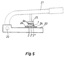
- a special tool (fig. 5) provided with perforating pins 9a, corresponding to the connector pins 9 but having slightly smaller diameters and used for making preliminary perforations in the conductors 2.
- a pre-perforation tool 25 is fastened to a shaft 21 which is capable of pivoting around a link 22.
- a perforation tool table 23 is provided with guides 24 for receiving a wire 1.
- the shaft 21 can be pressed downwards for making preliminary perforations in the conductors 2, whereby the connection of a wire can be effected with a lesser force with a structurally weaker connector, possibly containing electronic components.
- the connector be provided with a prefabricated housing but, instead, the connector area can be sealed hermetically with adhesive, resin or a like paste.
- the tips of pins 9 or 9a are designed as sharp points in view of providing an elongated cutting ridge 10 whose direction corresponds essentially to the longitudinal direction of the conductors.
- this direction is transversal relative to the direction of rolling.
- the direction of rolling refers to the direction in which most of the deformation occurs as the conductor is rolled from round to flat. As the conductor is flattening, the deformation in lateral direction exceeds that occurring in the longitudinal direction.
- the piercing of a conductor 2 proceeds in such a manner that in the mid-section of a conductor is first provided with an elongated incision having a length almost equal to the pin diameter, the conductor sections on either side of said incision turning downwards and pressing firmly against the sides of the pin 9 (or 9a), as shown in fig.3.
- the cutting ridge 10 has a length which is slightly less than the diameter of the pin 9 (or 9a).
- the edges of a hole produced in the conductor 2 will have a matching shape and, thus, the contact is guaranteed both by the slightly larger diameter of the connector pins 9 and by the elasticity of an insulating material which compresses the edges of a hole in the conductor 2 around the pin 9. Since the piercing pin 9a included in the tool is similar to the pin 9 shown in fig. 3, it has not been especially illustrated. It may be preferable that the pin 9 or 9a does not pierce the insulating sheath on the other side of the conductor, whereby the joint will have fewer points to be sealed.
- the connector housing 3 may be provided with a special socket element 14 for securing the lamp 12 along with its connector in a fixing hole at the point of service.
- Extending from the socket element 14 or elsewhere from the connector housing 3 are flexible tongues 15 which take hold of the opposite sides of the lamp 12 at its reduced neck portion 16 for immobilizing the lamp 12 in the connector 3, which in the illustrated case provides an intelligent fastening socket for the lamp 12.
- the connector 3 can be fitted e.g. with a contact plug, including a conductor for transmitting an electrical contact to a lamp or an actuator located further away from the connector.
- the intelligent connecting socket of a lamp can be located away from the connector 3.
- a connector of the invention is used in wire branching.
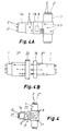
- a connector housing 3' includes two sets of pins 9, which are connected to each other by means of conductors 17 included in the connector 3' as integral components. Between the housing halves said connector housing is provided with suitable receiving slots for a wire 1 to be branched and for a branch wire 1a. When the housing halves (corresponding to housing halves 3a and 3b) are pressed against each other, the pins 9 penetrate through the flat conductors 2 and 2' for providing a permanent contact between the conductors included in wires 1 and la.
- this embodiment does not have an electronic component included in the connector 3' or a possibility of internal coding, as in the embodiment of figs. 1 and 2. However, it is possible to build an intelligent component also in a connector used in wire branchings, as designated at 18 in fig. 4A. Thus, the wire branch la is only supplied with electricity as determined by a control code.
- Fig. 4B illustrates yet another embodiment for a connector of the invention.
- the disconnectable wire joint comprises socket heads 19, 20, each of which is separately connected to a wire 1 by means of a connector 3'' of the invention.
Landscapes
- Engineering & Computer Science (AREA)
- Manufacturing & Machinery (AREA)
- Multi-Conductor Connections (AREA)
- Coupling Device And Connection With Printed Circuit (AREA)
- Connections By Means Of Piercing Elements, Nuts, Or Screws (AREA)
- Details Of Connecting Devices For Male And Female Coupling (AREA)
Claims (9)
- Leiterverbindung mit einem Kabelverbinder (3) zur Herstellung einer galvanischen Verbindung zwischen dem Verbinder (3) und Leitern (2), die von einem Isoliermantel (11) umgeben sind; der Verbinder (3) ist mit einer Vielzahl von Verbinderstiften (9) versehen, die sich durch den Isoliermantel (11) in direkten Kontakt mit den Leitern (2) erstrecken; der Verbinder (3) ist außerdem mit Leiterbändern (4; 5, 6) versehen, die mit den Verbinderstiften (9) zur Versorgung oder Lieferung von Elektrizität Kontakt haben, dadurch gekennzeichnet, daß die Verbinderstifte (9) sich durch die Leiter (2) erstrecken, die die Gestalt von flachen Metallstreifen haben, die nach untengewendete Lippenabschnitte aufweisen, die fest gegen die Seiten der Verbinderstifte (9) gepreßt sind.
- Leiterverbindung mit einem Kabelverbinder (3) zur Herstellung einer galvanischen Verbindung zwischen dem Verbinder (3) und flachen Metallstreifenleitern (2), die von einem Isoliermantel eines Kabels umgeben sind, dadurch gekennzeichnet, daß der Verbinder ein intelligentes Kontakt-Endstück (3) ist, das gesteuert Energie an ein energieverbrauchendes Verbrauchergerät (12) eines Fahrzeuges liefert, und daß das Kontakt-Endstück (3) an ein Kabel (1), das die genannten Flachleiter (2) enthält, mittels Verbinderstiften (9) angeschlossen ist, die durch die genannte Kabelisolierung (11) und durch die Flachleiter (2) hindurchdringen, die nach unten gewendete Lippenabschnitte haben, die fest gegen die Seiten der Verbinderstifte (9) gepreßt sind.
- Leiterverbindung nach einem der Ansprüche 1 oder 2, dadurch gekennzeichnet, daß mindestens ein Verbinderstift (9) mit einem Stromweg (6) vorgesehen ist, der Elemente zum externen Kodieren des Verbinders enthält.
- Leiterverbindung nach Anspruch 3, dadurch gekennzeichnet, daß sie zugerichtet ist, um über ein elektronisches Bauteil (8) Strom auf eine Signallampe (12) oder eine andere Lampe oder einen elektrischen Betätiger zu geben, so daß die Lampe oder der Betätiger mit einer Ein-/Ausschaltung versehen ist, die in Antwort auf einen Identifikationskode ansteht, der von einem Leiter (2') empfangen wird, der in einem Kabel (1) eingeschlossen ist, das zu verbinden ist.
- Leiterverbindung nach Anspruch 4, dadurch gekennzeichnet, daß das genannte elektrische Bauteil (8) und der genannte Verbinder (3) mit einem gemeisamen Gehäuse (3a, 3b) versehen sind.
- Leiterverbindung nach einem der Ansprüche 1 bis 5, dadurch gekennzeichnet, daß jener Verbinder (3) mit mindestens drei Verbinderstiften (9) versehen ist, von denen mindestens einer Kontakt zum Stromleiter (2) herstellt und mindestens einer Kontakt zum Kodeleiter (2') oder einem kombinierten Strom- und Kodeleiter herstellt.
- Werkzeug zur Herstellung einer Leiterverbindung gemäß Anspruch 1 oder 2, dadurch gekennzeichnet, daß jenes Werkzeug (25) einen scharf-spitz endenden Stift (9a) aufweist, der durch den Isoliermantel (11) und durch den Leiter (2) hindurch preßbar ist und daß der Werkzeugstift (9a) einen Durchmesser hat, der etwas geringer als der des Verbindungsstiftes (9) ist, und daß der Werkzeugstift (9a) eine Spitze hat, die als Schneidkante (10) dienen soll, die eine Länge hat, die etwas geringer ist als die Durchmesser der Stifte (9, 9a).
- Werkzeug nach Anspruch 7, dadurch gekennzeichnet, daß die Schneidkante (10) sich in eine Richtung erstreckt, die im wesentlichen quer zur Walzrichtung jenes Leiters (2) steht, der durchstochen werden soll.
- Verfahren zur Herstellung einer Leiterverbindung mit einem Werkzeug nach Anspruch 7, gekennzeichnet durch die Schritte, Erzeugen vorläufiger Löcher mittels des schneidspitzen Werkzeugstiftes (9a), die in den Isoliermantel (11) und durch den Leiter gepreßt werden, und Einschieben der Verbinderstifte (9) in die vorläufigen Löcher.
Applications Claiming Priority (3)
| Application Number | Priority Date | Filing Date | Title |
|---|---|---|---|
| FI935373 | 1993-12-01 | ||
| FI935373A FI935373A0 (fi) | 1993-12-01 | 1993-12-01 | Kopplingsstycke eller koppling foer ledning |
| PCT/FI1994/000542 WO1995015594A1 (en) | 1993-12-01 | 1994-12-01 | Conductor joint and tool and method for making the joint |
Publications (2)
| Publication Number | Publication Date |
|---|---|
| EP0730786A1 EP0730786A1 (de) | 1996-09-11 |
| EP0730786B1 true EP0730786B1 (de) | 1999-02-17 |
Family
ID=8539062
Family Applications (1)
| Application Number | Title | Priority Date | Filing Date |
|---|---|---|---|
| EP95901469A Expired - Lifetime EP0730786B1 (de) | 1993-12-01 | 1994-12-01 | Leiterverbindung und werkzeug sowie verfahren zur herstellung der verbindung |
Country Status (8)
| Country | Link |
|---|---|
| US (1) | US5997338A (de) |
| EP (1) | EP0730786B1 (de) |
| JP (1) | JPH09505935A (de) |
| AU (1) | AU1069895A (de) |
| DE (1) | DE69416602T2 (de) |
| ES (1) | ES2130569T3 (de) |
| FI (1) | FI935373A0 (de) |
| WO (1) | WO1995015594A1 (de) |
Families Citing this family (43)
| Publication number | Priority date | Publication date | Assignee | Title |
|---|---|---|---|---|
| DE19613385C2 (de) * | 1996-04-03 | 2001-08-23 | Liba Maschf | Kettenwirkmaschine mit mindestens einer Busleitungen aufweisenden Legebarre |
| FI101656B1 (fi) * | 1996-05-27 | 1998-07-31 | Iws International Inc | Älykkään liitäntäkannan ja kaapelin välinen liitos |
| DE29701828U1 (de) * | 1997-02-03 | 1997-04-10 | Siemens AG, 80333 München | Modul zum Anschluß eines Aktuators oder Sensors |
| HUP0003073A3 (en) * | 1997-07-11 | 2002-10-28 | Smithkline Beecham Plc | Benzenesulfonamide derivatives, process for producing them and their use as medicines |
| DE19742092A1 (de) * | 1997-09-24 | 1999-03-25 | Bosch Gmbh Robert | Elektrisch leitendes Kabel |
| AUPO947297A0 (en) * | 1997-09-26 | 1997-10-23 | Mannesmann Dematic Colby Pty Limited | Paperless picking systems |
| JP4144178B2 (ja) | 1997-11-14 | 2008-09-03 | アイダブリューエス インターナショナル インコーポレイテッド | インテリジェント電流分配システムおよびその製造方法 |
| FI113420B (fi) * | 1997-11-14 | 2004-04-15 | Iws Internat Inc Oy | Älykäs ohjausjärjestelmä kulkuneuvon virranjakelua varten |
| AU9164498A (en) * | 1998-09-10 | 2000-04-03 | Iws International Inc | Flat cable and its junction with an intelligent contact terminal |
| US7162332B2 (en) | 1999-07-30 | 2007-01-09 | Oshkosh Truck Corporation | Turret deployment system and method for a fire fighting vehicle |
| US6553290B1 (en) * | 2000-02-09 | 2003-04-22 | Oshkosh Truck Corporation | Equipment service vehicle having on-board diagnostic system |
| US6922615B2 (en) | 1999-07-30 | 2005-07-26 | Oshkosh Truck Corporation | Turret envelope control system and method for a fire fighting vehicle |
| US7729831B2 (en) | 1999-07-30 | 2010-06-01 | Oshkosh Corporation | Concrete placement vehicle control system and method |
| US6909944B2 (en) * | 1999-07-30 | 2005-06-21 | Oshkosh Truck Corporation | Vehicle control system and method |
| US7127331B2 (en) | 1999-07-30 | 2006-10-24 | Oshkosh Truck Corporation | Turret operator interface system and method for a fire fighting vehicle |
| US6885920B2 (en) | 1999-07-30 | 2005-04-26 | Oshkosh Truck Corporation | Control system and method for electric vehicle |
| US7072745B2 (en) | 1999-07-30 | 2006-07-04 | Oshkosh Truck Corporation | Refuse vehicle control system and method |
| US6882917B2 (en) * | 1999-07-30 | 2005-04-19 | Oshkosh Truck Corporation | Steering control system and method |
| US7184866B2 (en) | 1999-07-30 | 2007-02-27 | Oshkosh Truck Corporation | Equipment service vehicle with remote monitoring |
| US7184862B2 (en) | 1999-07-30 | 2007-02-27 | Oshkosh Truck Corporation | Turret targeting system and method for a fire fighting vehicle |
| US6993421B2 (en) | 1999-07-30 | 2006-01-31 | Oshkosh Truck Corporation | Equipment service vehicle with network-assisted vehicle service and repair |
| US7024296B2 (en) | 1999-07-30 | 2006-04-04 | Oshkosh Truck Corporation | Control system and method for an equipment service vehicle |
| US7006902B2 (en) | 1999-07-30 | 2006-02-28 | Oshkosh Truck Corporation | Control system and method for an equipment service vehicle |
| US7107129B2 (en) | 2002-02-28 | 2006-09-12 | Oshkosh Truck Corporation | Turret positioning system and method for a fire fighting vehicle |
| US7379797B2 (en) | 2001-01-31 | 2008-05-27 | Oshkosh Truck Corporation | System and method for braking in an electric vehicle |
| US7277782B2 (en) | 2001-01-31 | 2007-10-02 | Oshkosh Truck Corporation | Control system and method for electric vehicle |
| US7792618B2 (en) | 2001-12-21 | 2010-09-07 | Oshkosh Corporation | Control system and method for a concrete vehicle |
| US7302320B2 (en) | 2001-12-21 | 2007-11-27 | Oshkosh Truck Corporation | Failure mode operation for an electric vehicle |
| US7254468B2 (en) | 2001-12-21 | 2007-08-07 | Oshkosh Truck Corporation | Multi-network control system for a vehicle |
| US7412307B2 (en) | 2002-08-02 | 2008-08-12 | Oshkosh Truck Corporation | Refuse vehicle control system and method |
| FR2844641B1 (fr) * | 2002-09-16 | 2004-10-22 | Valeo Electronique Sys Liaison | Ensemble de cablages et connecteur correspondant |
| US7048398B2 (en) * | 2003-08-05 | 2006-05-23 | Bahram Bahramian | Low profile light panel |
| DE102005016512A1 (de) * | 2005-04-11 | 2006-10-12 | Ingo Maurer Gmbh | Beleuchtungssystem |
| US8139109B2 (en) | 2006-06-19 | 2012-03-20 | Oshkosh Corporation | Vision system for an autonomous vehicle |
| US8947531B2 (en) | 2006-06-19 | 2015-02-03 | Oshkosh Corporation | Vehicle diagnostics based on information communicated between vehicles |
| WO2010045547A2 (en) * | 2008-10-17 | 2010-04-22 | Richard Temblador | Continuous flexible bus |
| US9302996B2 (en) | 2010-12-17 | 2016-04-05 | Mitsubishi Tanabe Pharma Corporation | Continuous arycyclic compound |
| JP5875098B2 (ja) * | 2011-06-30 | 2016-03-02 | 矢崎総業株式会社 | ワイヤハーネス構造体、及び、電子機器制御システム |
| US9546155B2 (en) | 2012-06-15 | 2017-01-17 | Mitsubishi Tanabe Pharma Corporation | Aromatic heterocyclic compound |
| US9845191B2 (en) | 2013-08-02 | 2017-12-19 | Oshkosh Corporation | Ejector track for refuse vehicle |
| CN105337128B (zh) * | 2014-08-12 | 2018-03-30 | 杭州纳雄科技有限公司 | 接口转接线以及标准模块 |
| JP6616798B2 (ja) * | 2017-05-10 | 2019-12-04 | 矢崎総業株式会社 | コネクタ及びコネクタ製造方法 |
| US11906144B1 (en) * | 2022-08-04 | 2024-02-20 | Seasons 4, Inc. | Light socket for flat ribbon cable with selectable wire connection |
Family Cites Families (13)
| Publication number | Priority date | Publication date | Assignee | Title |
|---|---|---|---|---|
| US2745078A (en) * | 1953-11-20 | 1956-05-08 | Jr Thomas J Wood | Detachable electric circuit connecting device having conductor sheath penetrating means |
| US3213404A (en) * | 1961-08-01 | 1965-10-19 | Thomas & Betts Corp | Means for connecting electrical conductors |
| BE789365A (fr) * | 1971-09-30 | 1973-03-27 | Amp Inc | Connecteur electrique |
| CH569370A5 (de) * | 1973-05-23 | 1975-11-14 | Amacher Hans | |
| US4259778A (en) * | 1979-05-25 | 1981-04-07 | Thomas & Betts Corporation | Punch and crimp apparatus |
| CH662906A5 (en) * | 1984-02-15 | 1987-10-30 | Bag Broncewarenfab Ag | Electrical connecting device |
| US4941843A (en) * | 1987-08-18 | 1990-07-17 | Johannesburg Construction Corporation (Proprietary) Limited | Electrical trunkline system |
| US4948381A (en) * | 1987-12-25 | 1990-08-14 | Daiichi Denshi Kogyo Kabushiki Kaisha | Insulation-piercing connector |
| DE3920367A1 (de) * | 1989-06-22 | 1991-01-10 | Minnesota Mining & Mfg | Vorrichtung zum verbinden einer vielzahl von draehten mit elektrischen kontakten |
| US5044964A (en) * | 1990-07-30 | 1991-09-03 | Xerox Corporation | Programmable connector module |
| FI95420C (fi) * | 1991-11-13 | 1997-05-14 | Heikki Korkala | Älykäs lamppu tai lampun älykäs liitäntäkanta |
| SE470275B (sv) * | 1991-12-19 | 1993-12-20 | Sandor Katona | Förfaringssätt för att fästa anslutningsbleck till elektriska ledare i tryckt krets |
| US5368490A (en) * | 1993-02-01 | 1994-11-29 | Mckissick; Todd A. | Switchable power outlet |
-
1993
- 1993-12-01 FI FI935373A patent/FI935373A0/fi not_active Application Discontinuation
-
1994
- 1994-12-01 WO PCT/FI1994/000542 patent/WO1995015594A1/en not_active Ceased
- 1994-12-01 JP JP7515429A patent/JPH09505935A/ja active Pending
- 1994-12-01 AU AU10698/95A patent/AU1069895A/en not_active Abandoned
- 1994-12-01 EP EP95901469A patent/EP0730786B1/de not_active Expired - Lifetime
- 1994-12-01 ES ES95901469T patent/ES2130569T3/es not_active Expired - Lifetime
- 1994-12-01 DE DE69416602T patent/DE69416602T2/de not_active Expired - Fee Related
- 1994-12-01 US US08/648,013 patent/US5997338A/en not_active Expired - Fee Related
Also Published As
| Publication number | Publication date |
|---|---|
| FI935373A0 (fi) | 1993-12-01 |
| EP0730786A1 (de) | 1996-09-11 |
| DE69416602D1 (de) | 1999-03-25 |
| WO1995015594A1 (en) | 1995-06-08 |
| ES2130569T3 (es) | 1999-07-01 |
| DE69416602T2 (de) | 1999-06-17 |
| US5997338A (en) | 1999-12-07 |
| AU1069895A (en) | 1995-06-19 |
| JPH09505935A (ja) | 1997-06-10 |
Similar Documents
| Publication | Publication Date | Title |
|---|---|---|
| US5997338A (en) | Conductor joint for connecting an intelligent socket to a cable | |
| US6096978A (en) | Flat cable and method for its manufacture | |
| US6261119B1 (en) | Led light strip insulation-piercing connector | |
| US5339232A (en) | Miniature light set | |
| US6702607B2 (en) | Wiring harness and manufacturing method of the same | |
| EP1965123A1 (de) | Beleuchtungsvorrichtungskabel und Beleuchtungsvorrichtung damit | |
| US6354868B1 (en) | Vehicle power distribution box | |
| US20090147509A1 (en) | Configurable led lighting strip | |
| CA1070401A (en) | Electrical contact | |
| JP2000510993A (ja) | インテリジェントコンタクトターミナルとケーブル間の接合部 | |
| US5944463A (en) | Clamp connection of electrical wiring and electrical lead structure | |
| HK174196A (en) | Combination back-up light and sound emitting device for automotive vehicle | |
| EP1180815B1 (de) | Verbindungsstruktur von elektrischen Drähten einer Lampeneinheit | |
| US6086388A (en) | Auxiliary switch system for use with removable circuit breaker | |
| US5639246A (en) | Electrical connector for trailer | |
| US5794332A (en) | Method of producing a plurality of press-connecting joint connectors | |
| US5281760A (en) | Terminal fitting for a high voltage resistor wire | |
| US20090009977A1 (en) | Three-Dimensional Wiring Body for Mounting Electronic Component and Electronic Component Mounting Structure | |
| US4049334A (en) | Wire preparation and termination means and method | |
| US4105898A (en) | Multi-beam light switch | |
| US7563143B2 (en) | Lighting apparatus | |
| EP0373343A2 (de) | Verfahren und Vorrichtung zum Verbinden an Drähte eines flexiblen Kabels | |
| US4725247A (en) | Cable splicing assembly | |
| FI113305B (fi) | Johdinliitos ja työkalu ja menetelmä sen valmistamiseksi | |
| US20120235206A1 (en) | Lighting device and method for contacting a lighting device |
Legal Events
| Date | Code | Title | Description |
|---|---|---|---|
| PUAI | Public reference made under article 153(3) epc to a published international application that has entered the european phase |
Free format text: ORIGINAL CODE: 0009012 |
|
| 17P | Request for examination filed |
Effective date: 19960611 |
|
| AK | Designated contracting states |
Kind code of ref document: A1 Designated state(s): DE ES FR GB IE IT NL SE |
|
| 17Q | First examination report despatched |
Effective date: 19961227 |
|
| GRAG | Despatch of communication of intention to grant |
Free format text: ORIGINAL CODE: EPIDOS AGRA |
|
| GRAG | Despatch of communication of intention to grant |
Free format text: ORIGINAL CODE: EPIDOS AGRA |
|
| GRAH | Despatch of communication of intention to grant a patent |
Free format text: ORIGINAL CODE: EPIDOS IGRA |
|
| GRAH | Despatch of communication of intention to grant a patent |
Free format text: ORIGINAL CODE: EPIDOS IGRA |
|
| GRAA | (expected) grant |
Free format text: ORIGINAL CODE: 0009210 |
|
| ITF | It: translation for a ep patent filed | ||
| AK | Designated contracting states |
Kind code of ref document: B1 Designated state(s): DE ES FR GB IE IT NL SE |
|
| REG | Reference to a national code |
Ref country code: IE Ref legal event code: FG4D |
|
| REF | Corresponds to: |
Ref document number: 69416602 Country of ref document: DE Date of ref document: 19990325 |
|
| ET | Fr: translation filed | ||
| REG | Reference to a national code |
Ref country code: ES Ref legal event code: FG2A Ref document number: 2130569 Country of ref document: ES Kind code of ref document: T3 |
|
| PLBE | No opposition filed within time limit |
Free format text: ORIGINAL CODE: 0009261 |
|
| STAA | Information on the status of an ep patent application or granted ep patent |
Free format text: STATUS: NO OPPOSITION FILED WITHIN TIME LIMIT |
|
| 26N | No opposition filed | ||
| PGFP | Annual fee paid to national office [announced via postgrant information from national office to epo] |
Ref country code: NL Payment date: 20011120 Year of fee payment: 8 |
|
| PGFP | Annual fee paid to national office [announced via postgrant information from national office to epo] |
Ref country code: IE Payment date: 20011121 Year of fee payment: 8 |
|
| PGFP | Annual fee paid to national office [announced via postgrant information from national office to epo] |
Ref country code: ES Payment date: 20011211 Year of fee payment: 8 |
|
| REG | Reference to a national code |
Ref country code: GB Ref legal event code: IF02 |
|
| PGFP | Annual fee paid to national office [announced via postgrant information from national office to epo] |
Ref country code: GB Payment date: 20021115 Year of fee payment: 9 |
|
| PG25 | Lapsed in a contracting state [announced via postgrant information from national office to epo] |
Ref country code: IE Free format text: LAPSE BECAUSE OF NON-PAYMENT OF DUE FEES Effective date: 20021202 Ref country code: ES Free format text: LAPSE BECAUSE OF NON-PAYMENT OF DUE FEES Effective date: 20021202 |
|
| PG25 | Lapsed in a contracting state [announced via postgrant information from national office to epo] |
Ref country code: NL Free format text: LAPSE BECAUSE OF NON-PAYMENT OF DUE FEES Effective date: 20030701 |
|
| NLV4 | Nl: lapsed or anulled due to non-payment of the annual fee |
Effective date: 20030701 |
|
| REG | Reference to a national code |
Ref country code: IE Ref legal event code: MM4A |
|
| PG25 | Lapsed in a contracting state [announced via postgrant information from national office to epo] |
Ref country code: GB Free format text: LAPSE BECAUSE OF NON-PAYMENT OF DUE FEES Effective date: 20031201 |
|
| GBPC | Gb: european patent ceased through non-payment of renewal fee |
Effective date: 20031201 |
|
| REG | Reference to a national code |
Ref country code: ES Ref legal event code: FD2A Effective date: 20021202 |
|
| PGFP | Annual fee paid to national office [announced via postgrant information from national office to epo] |
Ref country code: IT Payment date: 20071121 Year of fee payment: 14 |
|
| PGFP | Annual fee paid to national office [announced via postgrant information from national office to epo] |
Ref country code: SE Payment date: 20071119 Year of fee payment: 14 |
|
| PGFP | Annual fee paid to national office [announced via postgrant information from national office to epo] |
Ref country code: FR Payment date: 20071114 Year of fee payment: 14 |
|
| PGFP | Annual fee paid to national office [announced via postgrant information from national office to epo] |
Ref country code: DE Payment date: 20071128 Year of fee payment: 14 |
|
| EUG | Se: european patent has lapsed | ||
| REG | Reference to a national code |
Ref country code: FR Ref legal event code: ST Effective date: 20090831 |
|
| PG25 | Lapsed in a contracting state [announced via postgrant information from national office to epo] |
Ref country code: DE Free format text: LAPSE BECAUSE OF NON-PAYMENT OF DUE FEES Effective date: 20090701 |
|
| PG25 | Lapsed in a contracting state [announced via postgrant information from national office to epo] |
Ref country code: FR Free format text: LAPSE BECAUSE OF NON-PAYMENT OF DUE FEES Effective date: 20081231 |
|
| PG25 | Lapsed in a contracting state [announced via postgrant information from national office to epo] |
Ref country code: SE Free format text: LAPSE BECAUSE OF NON-PAYMENT OF DUE FEES Effective date: 20081202 |
|
| PG25 | Lapsed in a contracting state [announced via postgrant information from national office to epo] |
Ref country code: IT Free format text: LAPSE BECAUSE OF NON-PAYMENT OF DUE FEES Effective date: 20081201 |