EP0730718B1 - Zufuhrverfahren und vorrichtung zur regelung des mischungszustandes in einer verbrennungs- oder vergasungsanlage - Google Patents
Zufuhrverfahren und vorrichtung zur regelung des mischungszustandes in einer verbrennungs- oder vergasungsanlage Download PDFInfo
- Publication number
- EP0730718B1 EP0730718B1 EP95903094A EP95903094A EP0730718B1 EP 0730718 B1 EP0730718 B1 EP 0730718B1 EP 95903094 A EP95903094 A EP 95903094A EP 95903094 A EP95903094 A EP 95903094A EP 0730718 B1 EP0730718 B1 EP 0730718B1
- Authority
- EP
- European Patent Office
- Prior art keywords
- tubes
- combustion
- chamber
- fluid
- gasification
- Prior art date
- Legal status (The legal status is an assumption and is not a legal conclusion. Google has not performed a legal analysis and makes no representation as to the accuracy of the status listed.)
- Expired - Lifetime
Links
- 238000002485 combustion reaction Methods 0.000 title claims description 73
- 238000000034 method Methods 0.000 title claims description 26
- 238000002309 gasification Methods 0.000 title claims description 23
- 238000002156 mixing Methods 0.000 title claims description 11
- 239000012530 fluid Substances 0.000 claims description 27
- 239000003546 flue gas Substances 0.000 claims description 19
- UGFAIRIUMAVXCW-UHFFFAOYSA-N Carbon monoxide Chemical compound [O+]#[C-] UGFAIRIUMAVXCW-UHFFFAOYSA-N 0.000 claims description 18
- 239000007789 gas Substances 0.000 claims description 18
- 238000004140 cleaning Methods 0.000 claims description 15
- 238000006073 displacement reaction Methods 0.000 claims description 6
- 230000008569 process Effects 0.000 claims description 6
- 239000000567 combustion gas Substances 0.000 claims description 5
- 239000012809 cooling fluid Substances 0.000 claims description 5
- 230000007246 mechanism Effects 0.000 claims description 4
- 230000008859 change Effects 0.000 claims description 3
- 230000003213 activating effect Effects 0.000 claims description 2
- 239000000446 fuel Substances 0.000 description 22
- 239000002245 particle Substances 0.000 description 13
- 239000002893 slag Substances 0.000 description 11
- GQPLMRYTRLFLPF-UHFFFAOYSA-N Nitrous Oxide Chemical compound [O-][N+]#N GQPLMRYTRLFLPF-UHFFFAOYSA-N 0.000 description 8
- LFQSCWFLJHTTHZ-UHFFFAOYSA-N Ethanol Chemical compound CCO LFQSCWFLJHTTHZ-UHFFFAOYSA-N 0.000 description 6
- 239000000428 dust Substances 0.000 description 5
- IJGRMHOSHXDMSA-UHFFFAOYSA-N Atomic nitrogen Chemical compound N#N IJGRMHOSHXDMSA-UHFFFAOYSA-N 0.000 description 4
- 235000008733 Citrus aurantifolia Nutrition 0.000 description 4
- 235000011941 Tilia x europaea Nutrition 0.000 description 4
- 239000004571 lime Substances 0.000 description 4
- VNWKTOKETHGBQD-UHFFFAOYSA-N methane Chemical compound C VNWKTOKETHGBQD-UHFFFAOYSA-N 0.000 description 4
- 238000005457 optimization Methods 0.000 description 4
- 239000007787 solid Substances 0.000 description 4
- 239000004071 soot Substances 0.000 description 4
- 239000002699 waste material Substances 0.000 description 4
- 238000000151 deposition Methods 0.000 description 3
- 230000008021 deposition Effects 0.000 description 3
- 239000003915 liquefied petroleum gas Substances 0.000 description 3
- MWUXSHHQAYIFBG-UHFFFAOYSA-N nitrogen oxide Inorganic materials O=[N] MWUXSHHQAYIFBG-UHFFFAOYSA-N 0.000 description 3
- 239000000126 substance Substances 0.000 description 3
- HGUFODBRKLSHSI-UHFFFAOYSA-N 2,3,7,8-tetrachloro-dibenzo-p-dioxin Chemical compound O1C2=CC(Cl)=C(Cl)C=C2OC2=C1C=C(Cl)C(Cl)=C2 HGUFODBRKLSHSI-UHFFFAOYSA-N 0.000 description 2
- XSQUKJJJFZCRTK-UHFFFAOYSA-N Urea Chemical compound NC(N)=O XSQUKJJJFZCRTK-UHFFFAOYSA-N 0.000 description 2
- 230000009471 action Effects 0.000 description 2
- 239000003570 air Substances 0.000 description 2
- QVGXLLKOCUKJST-UHFFFAOYSA-N atomic oxygen Chemical compound [O] QVGXLLKOCUKJST-UHFFFAOYSA-N 0.000 description 2
- 239000002551 biofuel Substances 0.000 description 2
- 230000005587 bubbling Effects 0.000 description 2
- 239000004202 carbamide Substances 0.000 description 2
- 239000003245 coal Substances 0.000 description 2
- 230000000694 effects Effects 0.000 description 2
- 229930195733 hydrocarbon Natural products 0.000 description 2
- 150000002430 hydrocarbons Chemical class 0.000 description 2
- 239000007788 liquid Substances 0.000 description 2
- 239000003345 natural gas Substances 0.000 description 2
- 229910052757 nitrogen Inorganic materials 0.000 description 2
- 230000003287 optical effect Effects 0.000 description 2
- 239000001301 oxygen Substances 0.000 description 2
- 229910052760 oxygen Inorganic materials 0.000 description 2
- 239000003415 peat Substances 0.000 description 2
- 239000004449 solid propellant Substances 0.000 description 2
- 239000002023 wood Substances 0.000 description 2
- QGZKDVFQNNGYKY-UHFFFAOYSA-N Ammonia Chemical compound N QGZKDVFQNNGYKY-UHFFFAOYSA-N 0.000 description 1
- 229910000831 Steel Inorganic materials 0.000 description 1
- NINIDFKCEFEMDL-UHFFFAOYSA-N Sulfur Chemical compound [S] NINIDFKCEFEMDL-UHFFFAOYSA-N 0.000 description 1
- 239000005864 Sulphur Substances 0.000 description 1
- RAHZWNYVWXNFOC-UHFFFAOYSA-N Sulphur dioxide Chemical compound O=S=O RAHZWNYVWXNFOC-UHFFFAOYSA-N 0.000 description 1
- 239000000654 additive Substances 0.000 description 1
- 239000004568 cement Substances 0.000 description 1
- 239000000919 ceramic Substances 0.000 description 1
- 239000007795 chemical reaction product Substances 0.000 description 1
- 239000003638 chemical reducing agent Substances 0.000 description 1
- 239000003795 chemical substances by application Substances 0.000 description 1
- 239000002894 chemical waste Substances 0.000 description 1
- 239000011248 coating agent Substances 0.000 description 1
- 238000000576 coating method Methods 0.000 description 1
- 230000036461 convulsion Effects 0.000 description 1
- 238000001816 cooling Methods 0.000 description 1
- 238000010168 coupling process Methods 0.000 description 1
- 238000005859 coupling reaction Methods 0.000 description 1
- 239000012717 electrostatic precipitator Substances 0.000 description 1
- 238000009422 external insulation Methods 0.000 description 1
- 238000004868 gas analysis Methods 0.000 description 1
- 239000011521 glass Substances 0.000 description 1
- 231100001261 hazardous Toxicity 0.000 description 1
- 239000002920 hazardous waste Substances 0.000 description 1
- 238000010438 heat treatment Methods 0.000 description 1
- 239000011261 inert gas Substances 0.000 description 1
- 238000003780 insertion Methods 0.000 description 1
- 230000037431 insertion Effects 0.000 description 1
- 239000003077 lignite Substances 0.000 description 1
- 238000004519 manufacturing process Methods 0.000 description 1
- 238000005259 measurement Methods 0.000 description 1
- 239000002184 metal Substances 0.000 description 1
- 229910052751 metal Inorganic materials 0.000 description 1
- 150000002739 metals Chemical class 0.000 description 1
- 239000000203 mixture Substances 0.000 description 1
- 235000013842 nitrous oxide Nutrition 0.000 description 1
- 239000007800 oxidant agent Substances 0.000 description 1
- 239000004033 plastic Substances 0.000 description 1
- 239000000843 powder Substances 0.000 description 1
- 238000002360 preparation method Methods 0.000 description 1
- 239000010802 sludge Substances 0.000 description 1
- 239000010959 steel Substances 0.000 description 1
- 239000004575 stone Substances 0.000 description 1
- 239000010902 straw Substances 0.000 description 1
- 239000004753 textile Substances 0.000 description 1
- XLYOFNOQVPJJNP-UHFFFAOYSA-N water Substances O XLYOFNOQVPJJNP-UHFFFAOYSA-N 0.000 description 1
Images

Classifications
-
- F—MECHANICAL ENGINEERING; LIGHTING; HEATING; WEAPONS; BLASTING
- F23—COMBUSTION APPARATUS; COMBUSTION PROCESSES
- F23J—REMOVAL OR TREATMENT OF COMBUSTION PRODUCTS OR COMBUSTION RESIDUES; FLUES
- F23J3/00—Removing solid residues from passages or chambers beyond the fire, e.g. from flues by soot blowers
-
- F—MECHANICAL ENGINEERING; LIGHTING; HEATING; WEAPONS; BLASTING
- F23—COMBUSTION APPARATUS; COMBUSTION PROCESSES
- F23J—REMOVAL OR TREATMENT OF COMBUSTION PRODUCTS OR COMBUSTION RESIDUES; FLUES
- F23J7/00—Arrangement of devices for supplying chemicals to fire
-
- F—MECHANICAL ENGINEERING; LIGHTING; HEATING; WEAPONS; BLASTING
- F23—COMBUSTION APPARATUS; COMBUSTION PROCESSES
- F23L—SUPPLYING AIR OR NON-COMBUSTIBLE LIQUIDS OR GASES TO COMBUSTION APPARATUS IN GENERAL ; VALVES OR DAMPERS SPECIALLY ADAPTED FOR CONTROLLING AIR SUPPLY OR DRAUGHT IN COMBUSTION APPARATUS; INDUCING DRAUGHT IN COMBUSTION APPARATUS; TOPS FOR CHIMNEYS OR VENTILATING SHAFTS; TERMINALS FOR FLUES
- F23L9/00—Passages or apertures for delivering secondary air for completing combustion of fuel
- F23L9/02—Passages or apertures for delivering secondary air for completing combustion of fuel by discharging the air above the fire
Definitions
- the present invention concerns a method of the kind stated in Claim 1.
- the invention also concerns a feeding apparatus for implementing the method.
- Nitrogen oxides are at present the most exposed flue gas components, especially when considering tariff which has been introduced in Sweden for plants larger than 10 MW and with an annual energy production greater than 50 GWh.
- the fuel composition often varies from one operation condition to another, particularly with regard to different types of waste fuels and also wood fuels.
- Examples of ash and/or slag enriched fuels comprise wood fuels, straw, waste such as industrial, municipal, hazardous and chemical waste and also hard coal, lignite, peat, lime sludge and black liquor. Also crematories and cement kilns are included in this category of combustion/gasification systems.
- Al is a term which designates an inorganic and unburnable substance which is originally within the fuel.
- Slag is a term which designates “additives” of inorganic and unburnable substances, such as metals, ceramics, glass, stone etcetera. "Ash” is often considered contained within the term “slag”. Examples of not ash and/or slag enriched fuels are oil, natural gas, LPG and certain biofuels.
- Fuel price is another important parameter for optimization of flue gas or gas parameters. Sulphur content and to a certain degree also nitrogen content in the fuel are directly proportional to the emission level ahead of a flue gas cleaning system. This of cource has the consequence that the fuel price becomes higher when i.e. the nitrogen content in the fuel is lower. Of course also the economical result is influenced by the market price and this will sometimes change quickly.
- the perforated tubes in the combustion or gasification chamber are fed by a fluid comprising a gas or a liquid or possible solid particles.
- gas are air, oxygen, oxygen-enriched air, flue gas, inert gas (CO 2 , N 2 etc), fuel for reburning (LPG, natural gas, ethanol, etc) NO x reducing substances (NH 3 , urea etc) and steam with an optimal flow, pressure and temperature.
- liquids are water, NH 3 , urea, ethanol and other organic solution agents, etc.
- solid particles are powder from biofuel including peat, coal and waste (plastic etc). These can be used as a reburning fuel.
- oxidizing agents e.g. air
- reducing agents e.g. NH 3 or for example LPG
- the tube or the tubes is/are suitably positioned in the combustion/gasification plant to present optimal conditions.
- the tube or tubes can be placed over the grate in connection with the first draught of the boiler.
- under combustion the reverse will apply.
- the tube or tubes can be positioned in the combustion chamber, for instance above the bed in a bubbling bed.
- kilns and furnaces such as these are those that the flue gas emissions of CO, C x H y (hydrocarbons), NO x , SO 2 , N 2 O, dioxine, PAH among others often are high due to poor combustion optimized plants.
- flue gas cleaning systems e.g. electrostatic precipitators or textile filters, SCR, scrubbers etcetera which are positioned after the combustion/gasification apparatus, which reduces the emission level in the subsequent stack/gas channel.
- EP-0 286 077 A2 (Müllverbrennungsstrom Wuppertal) describes a method of burning waste in which the flue gas is drawn out of the furnace and made to make a swirling movement by the addition of secondary air.
- the secondary air is fed through nozzles in such a way that the flow of flue gases is slowed down in a uniform temperature zone in the furnace and then allowed to remain there for approximately 8 seconds.
- SE,C,139 072 (Larsson) describes a furnace, especially in a heating boiler or for connection to similar boilers' fire rooms in which intakes for the primary air are located on the side of the furnace, said intakes leading to one or several fixed tubes along the furnace, which in their turn contain a rotatable tube which regulates the outlet area for air by twisting the tube about its axis and/or axial displacement of the tube.
- SE,C,115 046 (Sinding) describes an apparatus for preheating and adjusting the supply of secondary air to furnaces, which apparatus is furnished with concentric tubes positioned close together and extending into a preheating chamber to supply air to the chamber and are mutually rotatable so that its openings can be set at an angle to one another for the adjustment of the area of passage and thereby the air supply.
- Feeding apparatuses in the shape of a perforated tube which injects into a combustion chamber are known, for example through WO-A1-91/00134 (Fuel Tech Europe), US-A-4 883 003 (Hoskinson) and SE,C,139 563 (Svenska Maskinverken).
- FI-B-87014 (Tampella) describes an apparatus for feeding granular lime with the aid of a gas stream to a fire-place.
- a nozzle mounted at the end of a tubular arm to which a means for displacing the nozzle is coupled.
- the lime is fed to a place in the fire-place having a suitable position in the flue gas stream with regard to temperature.
- the preamble of the attached Claim 1 concerns a method of this kind which is deemed to constitute the closest prior art.
- any of the known systems permit an influence or effect on the mixing condition or mixing ratio between the combustion gases and/or between these and the fluid or fluids supplied or fed to the combustion chamber.
- one object of the invention is to minimize inherent disturbances in known methods of combustion and gasification including associated plants, thereby increasing the efficiency and reducing the emission levels in the combustion and gasification processes, respectively.
- Another object is to increase the flexibility of the method and the plant in order to, if so required, make possible a quick and simple adjustment from one desired emission level (e.g. high CO- low NO-concentration) to another (e.g. low CO- high NO-concentration) depending on the economical output.
- one desired emission level e.g. high CO- low NO-concentration
- another desired emission level e.g. low CO- high NO-concentration
- Yet another object is to achieve a method of minimizing disturbances and a feeding apparatus, respectively, which simplifies and cheapens cleaning of the tubes, thereby achieving an increased yield of the combustion and gasification processes, respectively.
- Another object is to accomplish a method and a plant, respectively, which renders it possible to continuously or at least almost continuously operate the combustion process, i.e. without having it to be stopped for soot removal or cleaning of the tubes for example feeding secondary air, and being contained in the combustion or gasification chamber, respectively.
- the same or different fluids can be supplied via the tubes which mutually coact in the way stated.
- a reburning fuel can be supplied which improves the prerequisites for controlling the temperature profile in the combustion chamber.
- the pipes to change the speed, flowing picture and direction of the fluid are rotated about their longitudinal axis.
- the pipes are displaced and/or rotated at impulse from transmitters positioned outside of the chamber and which sense the state of combustion.
- transmitters for temperature, pressure, flow, present flue gas components etcetera.
- optical transmitters may be used for the purpose.
- Signals generated by the transmitters can in addition be used to regulate the supply of fluid and solid particles, respectively, to the tubes, said supply possibly being performed by jerks or intermittently.
- the rotation of the perforated tubes can ascertain that the supply, if so desired, takes place at predetermined, varying angles within the combustion chamber.
- the pipes are displaced by holding and drive means positioned outside of the chamber and preferably engaging their ends so that the pipes are completely withdrawable from the chamber.
- the tubes are withdrawn to an inactive position outside of the chamber at impulse from one or several different transmitters activating the withdrawal mechanism at for instance power failure or failure of cooling fluid supply to the plant.
- the pipes are preferably mounted replaceable at the holder and drive means positioned outside of the chamber. Then a very simple adaption to different operation conditions for the plant will be possible which, thus, can be accomplished by a simple replacement of one or more of the supply tubes. It is realized that the arrrangement also facilitates preparation and service of the plant which is also made more cheap.
- inventive method can be put into practice on existing as well as new combustion/gasification plants.
- New boilers and furnaces, respectively can be manufactured with a smaller furnace volume due to a more effective mixing of the gases, which reduces costs.
- the best operation possible with optimal emission level at every separate occasion can more simply be obtained than with systems known heretofore.
- a cooling fluid can be added to reduce the temperature of the jacket of the tube to make slag and other dust deposition of such a kind that the cleaning operation is facilitated or the number of such operations minimized.
- Such a cooling fluid can possibly be supplied separately, possibly intermittently and preferably in connection with withdrawal of the pipes. It is preferably supplied via a ring column around each tube. Due to the cooling, slag and other dust deposition on the tubes become less glass-like or sticky whereby the cleaning operation will be simplified and speeded up.
- the invention also refers to a feeding apparatus for controlling the mixing condition or ratio in a combustion or gasification plant by means of the supplied fluid for optimizing flue gas or gas parameters, the essential features of said feeding apparatus being stated in Claim 8.
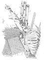
- Fig. 1 is a partly cut-away perspective view of a combustion plant for solid fuels having a feeding apparatus in accordance with the invention.
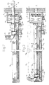
- Fig. 2 is a side view showing a feeding means according to the invention comprising a perforated tube and means for displacing, rotation, controlling and cleaning the tube positioned outside of the combustion chamber.
- the figure shows the feeding means in inserted position in the combustion chamber.
- Fig. 3 is a side view corresponding to Fig. 2 with the feeding means completely withdrawn from the combustion chamber.
- Fig. 4 is a sectional view along the line IV-IV in Fig. 3.
- Fig. 5 is a sectional horizontal view through the combustion chamber and shows three coacting feeding means at one level thereof for increasing the action of intermixing the fluid in the combustion gases.
- Fig. 6 is a schematic vertical sectional view through an alternative embodiment in which a number of different feeding devices for fluid are received in a "revolver-holder" positioned outside of the combustion chamber for optional, alternative insertion into the combustion chamber.
- the digit 1 denotes a combustion plant comprising a furnace 2 for combustion of solid fuels with a grate 3 and an upper combustion chamber 4.
- the fuel can be fed intermittently or continuously and combustion air in the form of primary air is blown from below and up through the grate 3.
- Secondary air is fed through a number of feeding apparatuses according to the present invention entering the combustion chamber 4 through special ports in the furnace wall 5 and further described below.
- the secondary air is supplied via said feeding apparatuses in order to complete the combustion of formed reaction products in the shape of gas and solid particles.
- Particles in the flue gas above the grate 3 consist of ash, slag and/or unburnt fuel. These can together form bigger particles, so called agglomerates, or be reduced to smaller, more or less clean ash particles. Slag enriched fuels often offer higher concentrations of dust and slag in the flue gas.
- Some of the particles form deposits on the inside of the combustion chamber which is often equipped with tubes 6 with an external insulation. Dust particles also deposit on the tubes 13 where the holes 13a for feeding secondary air are entirely or partially blocked thereby affecting the feed of secondary air, alternatively coating will occur directly on the mantle of the tube.
- the feeding tubes 13 for a fluid are arranged forming a curtain system comprising a number of tubes 13, some of which are parallell, at one or more levels in the combustion chamber 4.
- the tubes 13 are equipped with perforations 13a alongside the mantle surface of the entire tubes.
- the holes can be equally distributed and a row of holes can be positioned on each side of the tubes.
- the through-flow area of the holes 13a determines the flow of the fluid at a given pressure.
- a fluid e.g. secondary air at high pressure
- a fan 10 connected to a collecting box 11, to which flexible tubes 12 are connected, which with quick-couplings are connected to the end flanges 13b of the tubes 13.
- the opposite ends of the tubes can be plugged or provided with outlet openings (not shown).
- the tubes 13 are inserted and withdrawn from the chamber 4 in an axial direction at longer or shorter periods of time. In such a way the emission level of the combustion process can be maintained optimal.
- Figs 2 and 3 illustrate the mechanisms that have been used for displacing the tubes 13 into and out from, respectively, the combustion chamber 4 and for their rotation, guiding and cleaning.
- the tubes 13 are received in a casing 14 supporting some of the stated mechanisms.
- an electric motor 16 is used the output axes of which drives a disc 17.
- An endless belt or chain 20 is led around the disc and also around rollers 18, 19.
- To the belt 20 is secured a holder in the shape of a trolley 25 engaging the end of the tube 13 so as to form a bed 25b to make the tube at the same time rotatable around its longitudinal axis.
- the holder 25 is displaceably guided via a guide 26.
- Fig. 2 shows the tube 13 in inserted position in the combustion chamber whereas fig. 3 shows the tube completely withdrawn from the chamber.
- the holder 25 is then so adapted that simple replacement of tubes 13 can take part in the withdrawn position.
- An electric motor 27 drives a belt 28 which extends over a number of rollers 29 engaging the periphery of the tubes 13 to turn it around.
- the holder 25 is provided with forked legs 25a supporting the bed 25b in which the tube 13 rests.
- the holder or the trolley 25 is displaceably guided on the guide 26.
- the casing 14 In its forward end the casing 14 is connected to a housing 30 which receives the opposite guide rollers 15 for the tube and also an arrangement of steel brushes 21 between which the tubes pass when being withdrawn and thereafter inserted. These brushes 21 perform an efficient cleaning of the tubes, so that they are released from dust and slag depositions.
- an automatic shaking device spinning tool or similar, not shown
- acoustic sootblower infrasonics or ultrasonics
- Fig. 5 shows how the flow picture of a fluid supplied via adjacent tubes 13 can be changed, in part through displacement of one or more tubes to different positions in the combustion chamber 4 and in part through turning or rotation of one or more of the tubes. Further actuation of such a kind can also be obtained by changing the pressure, speed and/or flow of the supplied fluid. As appears from fig. 5 different intermixing conditions can be obtained as a result of that the flow of fluid from adjacent pipes can amplify or intensify each other, more or less extinct each other or present an action therebetween.
- a reburning-fuel such as ethanol
- ethanol can be supplied via one, two or all tubes 13, whereby the temperature profile, i.e. the temperature in different zones of the chamber 4, can be controlled to give an optimal combustion process.
- Fig. 6 shows a "revolver arrangement" in which casing 14 is replaced by a casing 14' which is rotatable on a shaft 40 and which receives a number of fluid supply tubes having different spacing and positions for perforations 13a thereon.
- casing 14' is rotated so that the fluid supply tube 13 which is most suitable in the actual situation is inserted into the combustion chamber 4.
- Attached to the ends of the tubes 13 are bellows-shaped hoses 12' for the fluid supply to each tube.
- the tubes 13 may have a length between 1 à 2 and 5 m and a diameter of 120-200 mm.
- the diameter of the perforations 13a may vary from 1 à 2 mm up to 2 à 4 cm and the distance between the perforations can amount to between 10 and 40 cm.
- the regulation of fluid to each tube 13 can further be made via output signals from transmitters for different gas parameters, gas concentrations, temperatures, pressure, flow etc (not shown). Said transmitters may also be used, e.g. via a computer, to decide when the cleaning or soot removal operations are to be initiated. As mentioned above there is then no need to stop the combustion process.
- digit 42 denotes a sensor of this kind.
- 43, 44 denote presence of an optical sensor where 44 is a lens.
- At for instance power failure or failure on cooling fluid supply to the plant one or more transmitters are sensing this and give an impulse for withdrawal of the tubes to an inactive position outside of the chamber. This is a very important safety measure within the scope of the inventive concept.
- a plant with a feeding apparatus according to the invention is simple to install and therefore particularly suitable when converting furnaces, combustion and gasification plants which are operating or already existing on the market.
- the tubes need not be oriented horizontally in the combustion chamber.
- One or more of the tubes may, thus, be inclined or extend vertically.
Landscapes
- Engineering & Computer Science (AREA)
- Mechanical Engineering (AREA)
- General Engineering & Computer Science (AREA)
- Chemical & Material Sciences (AREA)
- Combustion & Propulsion (AREA)
- Incineration Of Waste (AREA)
- Gasification And Melting Of Waste (AREA)
- Fluidized-Bed Combustion And Resonant Combustion (AREA)
Claims (10)
- Verfahren zur Regelung des Mischungszustandes in einer Verbrennungs- oder Vergasungsanlage, bei dem zur Optimierung des Gasflusses oder der Gasparameter ein Fluid via eine Zuführvorrichtung zugeführt wird, wobei diese Anlage eine Verbrennungs- oder eine Vergasungskammer (4) hat, in welcher zwei oder mehr perforierte Röhren aufgenommen sind, durch welche das Fluid in die Kammer gelangt, um darin einen Verbrennungs- oder Vergasungsprozess aufrechtzuerhalten, bei welchem wenigstens eine der beiden oder der mehreren perforierten Röhren (13) in der Kammer (4) in längeren oder kürzeren Zeitintervallen entlang ihrer Achse verschoben werden, dies für einen vorbestimmten, gesteuerten Einfluss auf die Vermischung des Fluides in den Verbrennungsgasen durch eine gemeinsame Kooperation zwischen den Röhren.
- Verfahren nach Anspruch 1, gekennzeichnet durch das Verschieben der Röhren durch Mittel auf der Aussenseite der Kammer (4), vorzugsweise durch an ihren Enden greifende Halter und Antriebsmittel (25; 16, 20), so dass die Röhren komplett aus der Kammer zurückgezogen werden können.
- Verfahren nach Anspruch 2, gekennzeichnet durch das Zurückziehen der Röhren (13) in eine inaktive Position ausserhalb der Kammer, durch einen Impuls von einem oder mehreren Übertragern, welche den Zurückziehmechanismus aktivieren, wie zum Beispiel bei einem Netzausfall oder bei einem Ausfall der Kühlungsfluidversorgung zur Anlage.
- Verfahren nach einem der Ansprüche 1 bis 3, gekennzeichnet durch zusätzliche Drehbarkeit der Röhren um ihre länglichen Achsen zwecks Änderung des Druckes, der Fluss-Struktur und/oder der Richtung.
- Verfahren nach einem der Ansprüche 1 bis 4, gekennzeichnet durch Verschieben und/oder Drehen der Röhren durch Impulse von einem oder mehreren Übertragern (42, 43, 44), welche ausserhalb der Kammer angeordnet sind und den Zustand der Verbrennung in der Kammer messen.
- Verfahren nach Anspruch 2, gekennzeichnet durch die auswechselbare Anordnung der Röhren am Halter und am Antriebsmittel.
- Verfahren nach einem der Ansprüche 2 bis 6, gekennzeichnetdurch eine Reinigung der Röhren, während sie zurückgezogen werden.
- Zuführeinrichtung in einer Verbrennungs- oder Vergasungsanlage zur Regulierung der Mischungszustände, bei dem zur Optimierung des Gasflusses oder der Gasparameter ein Fluid zugeführt wird, wobei diese Anlage eine Verbrennungs- oder eine Vergasungskammer (4) hat, in welcher zwei oder mehr perforierte Röhren aufgenommen sind, durch welche das Fluid in die Kammer gelangt, um darin einen Verbrennungsoder Vergasungsprozess aufrechtzuerhalten,bei welchem wenigstens eine der Röhren (13) in der Kammer (4) entlang ihrer Achse verschiebbar ist, Halter und Antriebsmittel (16, 20; 26; 15) eines oder mehrere der Enden der Röhren (13) ausserhalb der Kammer (4) halten für eine vorbestimmte, gesteuerte Verschiebung der Röhren zur Beeinflussung der Vermischung des Fluides im Verbrennungsgas durch eine gemeinsame Kooperation zwischen den Röhren; undein Mittel (z.B. 42 - 44), welches die Verschiebebewegungen in Abhängigkeit der Zeit und/oder dem in der Kammer festgestellten Zustand der Verbrennung ausführt.
- Zuführeinrichtung nach Anspruch 8, gekennzeichnet durch ein Mittel (27, 28, 29; 21, 38, 39) für eine Rotation und/oder eine Reinigung der Röhren.
- Zuführeinrichtung nach Anspruch 8 oder 9, gekennzeichnet durch den Halter und Antriebsmittel (25; 16, 20), welche derart ausgestaltet sind, dass mit ihnen ermöglicht ist, dass die Röhren (13) komplett aus der Kammer zurückgezogen und verschoben werden können.
Applications Claiming Priority (3)
| Application Number | Priority Date | Filing Date | Title |
|---|---|---|---|
| SE9304038 | 1993-12-03 | ||
| SE9304038A SE502283C2 (sv) | 1993-12-03 | 1993-12-03 | Sätt och tillförseldon för att reglera blandningsförhållanden i en förbrännings- eller förgasningsanläggning |
| PCT/SE1994/001163 WO1995015463A1 (en) | 1993-12-03 | 1994-12-02 | A method and a feeding apparatus for controlling mixing conditions in a combustion or gasification plant |
Publications (2)
| Publication Number | Publication Date |
|---|---|
| EP0730718A1 EP0730718A1 (de) | 1996-09-11 |
| EP0730718B1 true EP0730718B1 (de) | 1999-09-22 |
Family
ID=20391998
Family Applications (1)
| Application Number | Title | Priority Date | Filing Date |
|---|---|---|---|
| EP95903094A Expired - Lifetime EP0730718B1 (de) | 1993-12-03 | 1994-12-02 | Zufuhrverfahren und vorrichtung zur regelung des mischungszustandes in einer verbrennungs- oder vergasungsanlage |
Country Status (7)
| Country | Link |
|---|---|
| EP (1) | EP0730718B1 (de) |
| AU (1) | AU1208095A (de) |
| CA (1) | CA2177963A1 (de) |
| DK (1) | DK0730718T3 (de) |
| FI (1) | FI120217B (de) |
| SE (1) | SE502283C2 (de) |
| WO (1) | WO1995015463A1 (de) |
Families Citing this family (10)
| Publication number | Priority date | Publication date | Assignee | Title |
|---|---|---|---|---|
| SE512517C2 (sv) * | 1998-07-17 | 2000-03-27 | Ecomb Ab | Tillförseldon för en fluid till en förbränningskammare |
| SE515645C2 (sv) * | 2000-01-14 | 2001-09-17 | Ecomb Ab | Kameraförsett tillförseldon för en fluid till en förbränningskammare |
| SE0103822D0 (sv) * | 2001-11-16 | 2001-11-16 | Ecomb Ab | Combustion optimisation |
| SE536195C2 (sv) * | 2011-10-12 | 2013-06-18 | Ecomb Ab Publ | Tillförselanordning för förbränningskammare och metod därför |
| US20150292737A1 (en) * | 2012-10-11 | 2015-10-15 | Ecomb Ab (Publ) | Supply device for a combustion chamber |
| EP2724766A1 (de) | 2012-10-26 | 2014-04-30 | Alstom Technology Ltd | Verfahren zur Behandlung eines kohlenstoffdioxidreichen Rauchgases und Rauchgasbehandlungssystem |
| SE1550315A1 (en) | 2015-03-16 | 2016-09-17 | Ecomb Ab (Publ) | Supply device for a combustion chamber |
| SE541268C2 (en) * | 2015-12-23 | 2019-05-28 | Tekniska Verken I Linkoeping Ab | Arrangement and method for adaptive nitrogen oxide reduction in a combustion chamber |
| PL243551B1 (pl) | 2017-11-24 | 2023-09-11 | Ics Ind Combustion Systems Spolka Z Ograniczona Odpowiedzialnoscia | Sposób redukcji tlenków azotu oraz tlenku węgla w komorach paleniskowych kotłów wodnych i kotłów parowych, szczególnie kotłów rusztowych oraz układ do redukcji tlenków azotu i tlenku węgla w komorach paleniskowych kotłów wodnych i kotłów parowych, szczególnie kotłów rusztowych |
| PL246416B1 (pl) | 2019-03-21 | 2025-01-27 | Ics Ind Combustion Systems Spolka Z Ograniczona Odpowiedzialnoscia | Sposób redukcji tlenków azotu oraz tlenku węgla w komorach paleniskowych kotłów wodnych i kotłów parowych, szczególnie kotłów rusztowych oraz układ do redukcji tlenków azotu i tlenku węgla w komorach paleniskowych kotłów wodnych i kotłów parowych, szczególnie kotłów rusztowych |
Family Cites Families (5)
| Publication number | Priority date | Publication date | Assignee | Title |
|---|---|---|---|---|
| DE509959C (de) * | 1927-03-07 | 1930-10-15 | Stelian W Wasilkioty | Vorrichtung fuer Feuerungen zur Einfuehrung von Verbrennungsluft oder von einem Dampfluftgemisch in die Brennstoffschicht |
| FI87014C (fi) * | 1987-12-16 | 1992-11-10 | Tampella Oy Ab | Anordning foer matning av pulverformig kalk till en eldstad av en panna |
| US4883003A (en) * | 1988-09-26 | 1989-11-28 | Hoskinson Gordon H | Secondary combustion chamber for an incinerator |
| US5342592A (en) * | 1989-07-04 | 1994-08-30 | Fuel Tech Europe Ltd. | Lance-type injection apparatus for introducing chemical agents into flue gases |
| SE502188C2 (sv) * | 1992-06-05 | 1995-09-11 | Ulf Hagstroem | Sätt och anordning för att undvika störningar orsakade av beläggningar på tillförseldon till förbrännings- eller förgasningsanläggning |
-
1993
- 1993-12-03 SE SE9304038A patent/SE502283C2/sv unknown
-
1994
- 1994-12-02 AU AU12080/95A patent/AU1208095A/en not_active Abandoned
- 1994-12-02 WO PCT/SE1994/001163 patent/WO1995015463A1/en not_active Ceased
- 1994-12-02 CA CA002177963A patent/CA2177963A1/en not_active Abandoned
- 1994-12-02 EP EP95903094A patent/EP0730718B1/de not_active Expired - Lifetime
- 1994-12-02 DK DK95903094T patent/DK0730718T3/da active
-
1996
- 1996-05-29 FI FI962243A patent/FI120217B/fi not_active IP Right Cessation
Also Published As
| Publication number | Publication date |
|---|---|
| WO1995015463A1 (en) | 1995-06-08 |
| SE502283C2 (sv) | 1995-09-25 |
| FI120217B (fi) | 2009-07-31 |
| SE9304038L (sv) | 1995-06-04 |
| EP0730718A1 (de) | 1996-09-11 |
| CA2177963A1 (en) | 1995-06-08 |
| SE9304038D0 (sv) | 1993-12-03 |
| AU1208095A (en) | 1995-06-19 |
| FI962243A7 (fi) | 1996-06-03 |
| FI962243A0 (fi) | 1996-05-29 |
| DK0730718T3 (da) | 2000-03-27 |
Similar Documents
| Publication | Publication Date | Title |
|---|---|---|
| EP0642646B1 (de) | Verfahren zur minimierung der störung verursacht durch ablagerungen auf einer zufuhreinrichtung einer verbrennungs-oder vergasungsanlage und eine solche zufuhreinrichtung | |
| US6190628B1 (en) | Method for injecting NOx inhibiting liquid reagent into the flue gas of a boiler in response to a sensed temperature | |
| CA2082142C (en) | Method and apparatus for waste incineration | |
| US5630368A (en) | Coal feed and injection system for a coal-fired firetube boiler | |
| US5315941A (en) | Method and apparatus for injecting nox inhibiting reagent into the flue gas of a boiler | |
| WO2013055285A1 (en) | Combustion chamber supply device and method thereof | |
| EP0730718A1 (de) | Zufuhrverfahren und vorrichtung zur regelung des mischungszustandes in einer verbrennungs-oder vergasungsanlage | |
| HU178846B (en) | Stoker for firing solid fuel first for fulfilling the heat demand of family houses and single aparatments or smaller group of them | |
| GB2107206A (en) | Reduction of nox emission from fluidised bed combustion systems | |
| CN100402925C (zh) | 焚烧固体材料的方法和装置 | |
| CZ205894A3 (en) | Flue boiler | |
| KR101781373B1 (ko) | 연소실 구분연소에 따른 소각효율이 향상된 유동층 소각로 설비 | |
| US20060008393A1 (en) | Pollutant reduction system with adjustable angle injector for injecting pollutant reduction substance | |
| CA1309571C (en) | Method and apparatus for reducing sulfur dioxide content in flue gases | |
| CA2220144C (en) | Circulating fluid bed steam generator nox control | |
| EP0499184B2 (de) | Verbrennungsverfahren zum gleichseitigen Regeln von Stickstoffoxiden und Produkte von unvollständiger Verbrennung | |
| US20140356794A1 (en) | Combustion Chamber Supply Device and Method Thereof | |
| UA50718C2 (uk) | Спосіб зменшення вмісту оксидів азоту у димових газах промислових парових котлів та пальник для здійснення способу | |
| KR102078139B1 (ko) | 고체 연료 보일러 | |
| KR102419214B1 (ko) | 폐기물 소각 처리 시스템 | |
| FI126253B (en) | Method for reducing nitrogen oxide emissions in a bubbling fluidized bed boiler and bubbling fluidized bed boiler | |
| US20150292737A1 (en) | Supply device for a combustion chamber | |
| EP2766684A1 (de) | Kühlung der versorgungsvorrichtung einer verbrennungskammer | |
| SU1198327A2 (ru) | Способ сжигани бурых углей | |
| SU1041849A1 (ru) | Подина аппарата кип щего сло |
Legal Events
| Date | Code | Title | Description |
|---|---|---|---|
| PUAI | Public reference made under article 153(3) epc to a published international application that has entered the european phase |
Free format text: ORIGINAL CODE: 0009012 |
|
| 17P | Request for examination filed |
Effective date: 19960514 |
|
| AK | Designated contracting states |
Kind code of ref document: A1 Designated state(s): BE CH DK IE LI |
|
| RAP1 | Party data changed (applicant data changed or rights of an application transferred) |
Owner name: ECOMB AB |
|
| RIN1 | Information on inventor provided before grant (corrected) |
Inventor name: NORELIUS, ERIC Inventor name: HAGSTROEM, ULF |
|
| 17Q | First examination report despatched |
Effective date: 19980128 |
|
| RBV | Designated contracting states (corrected) |
Designated state(s): BE CH DK IE LI |
|
| REG | Reference to a national code |
Ref country code: DE Ref legal event code: 8566 |
|
| GRAG | Despatch of communication of intention to grant |
Free format text: ORIGINAL CODE: EPIDOS AGRA |
|
| GRAG | Despatch of communication of intention to grant |
Free format text: ORIGINAL CODE: EPIDOS AGRA |
|
| GRAH | Despatch of communication of intention to grant a patent |
Free format text: ORIGINAL CODE: EPIDOS IGRA |
|
| GRAH | Despatch of communication of intention to grant a patent |
Free format text: ORIGINAL CODE: EPIDOS IGRA |
|
| GRAA | (expected) grant |
Free format text: ORIGINAL CODE: 0009210 |
|
| AK | Designated contracting states |
Kind code of ref document: B1 Designated state(s): BE CH DK IE LI |
|
| REG | Reference to a national code |
Ref country code: CH Ref legal event code: EP |
|
| REG | Reference to a national code |
Ref country code: CH Ref legal event code: NV Representative=s name: LUCHS & PARTNER PATENTANWAELTE |
|
| REG | Reference to a national code |
Ref country code: IE Ref legal event code: FG4D |
|
| REG | Reference to a national code |
Ref country code: DK Ref legal event code: T3 |
|
| PLBE | No opposition filed within time limit |
Free format text: ORIGINAL CODE: 0009261 |
|
| STAA | Information on the status of an ep patent application or granted ep patent |
Free format text: STATUS: NO OPPOSITION FILED WITHIN TIME LIMIT |
|
| 26N | No opposition filed | ||
| PGFP | Annual fee paid to national office [announced via postgrant information from national office to epo] |
Ref country code: DK Payment date: 20101222 Year of fee payment: 17 |
|
| PGFP | Annual fee paid to national office [announced via postgrant information from national office to epo] |
Ref country code: IE Payment date: 20111223 Year of fee payment: 18 Ref country code: CH Payment date: 20111214 Year of fee payment: 18 |
|
| PGFP | Annual fee paid to national office [announced via postgrant information from national office to epo] |
Ref country code: BE Payment date: 20111216 Year of fee payment: 18 |
|
| BERE | Be: lapsed |
Owner name: *ECOMB A.B. Effective date: 20121231 |
|
| REG | Reference to a national code |
Ref country code: CH Ref legal event code: PL |
|
| REG | Reference to a national code |
Ref country code: DK Ref legal event code: EBP |
|
| REG | Reference to a national code |
Ref country code: IE Ref legal event code: MM4A |
|
| PG25 | Lapsed in a contracting state [announced via postgrant information from national office to epo] |
Ref country code: BE Free format text: LAPSE BECAUSE OF NON-PAYMENT OF DUE FEES Effective date: 20121231 |
|
| PG25 | Lapsed in a contracting state [announced via postgrant information from national office to epo] |
Ref country code: IE Free format text: LAPSE BECAUSE OF NON-PAYMENT OF DUE FEES Effective date: 20121202 Ref country code: CH Free format text: LAPSE BECAUSE OF NON-PAYMENT OF DUE FEES Effective date: 20121231 Ref country code: LI Free format text: LAPSE BECAUSE OF NON-PAYMENT OF DUE FEES Effective date: 20121231 |
|
| PG25 | Lapsed in a contracting state [announced via postgrant information from national office to epo] |
Ref country code: DK Free format text: LAPSE BECAUSE OF NON-PAYMENT OF DUE FEES Effective date: 20130102 |