EP0729893A2 - Blank for a tray having partitions - Google Patents
Blank for a tray having partitions Download PDFInfo
- Publication number
- EP0729893A2 EP0729893A2 EP96200552A EP96200552A EP0729893A2 EP 0729893 A2 EP0729893 A2 EP 0729893A2 EP 96200552 A EP96200552 A EP 96200552A EP 96200552 A EP96200552 A EP 96200552A EP 0729893 A2 EP0729893 A2 EP 0729893A2
- Authority
- EP
- European Patent Office
- Prior art keywords
- transverse
- blank
- panels
- panel
- die
- Prior art date
- Legal status (The legal status is an assumption and is not a legal conclusion. Google has not performed a legal analysis and makes no representation as to the accuracy of the status listed.)
- Granted
Links
Images


Classifications
-
- B—PERFORMING OPERATIONS; TRANSPORTING
- B65—CONVEYING; PACKING; STORING; HANDLING THIN OR FILAMENTARY MATERIAL
- B65D—CONTAINERS FOR STORAGE OR TRANSPORT OF ARTICLES OR MATERIALS, e.g. BAGS, BARRELS, BOTTLES, BOXES, CANS, CARTONS, CRATES, DRUMS, JARS, TANKS, HOPPERS, FORWARDING CONTAINERS; ACCESSORIES, CLOSURES, OR FITTINGS THEREFOR; PACKAGING ELEMENTS; PACKAGES
- B65D5/00—Rigid or semi-rigid containers of polygonal cross-section, e.g. boxes, cartons or trays, formed by folding or erecting one or more blanks made of paper
- B65D5/02—Rigid or semi-rigid containers of polygonal cross-section, e.g. boxes, cartons or trays, formed by folding or erecting one or more blanks made of paper by folding or erecting a single blank to form a tubular body with or without subsequent folding operations, or the addition of separate elements, to close the ends of the body
- B65D5/0263—Rigid or semi-rigid containers of polygonal cross-section, e.g. boxes, cartons or trays, formed by folding or erecting one or more blanks made of paper by folding or erecting a single blank to form a tubular body with or without subsequent folding operations, or the addition of separate elements, to close the ends of the body with end closures formed by inward folding of flaps, three of them being formed of a continuous strip, the fourth being a separate flap
-
- B—PERFORMING OPERATIONS; TRANSPORTING
- B65—CONVEYING; PACKING; STORING; HANDLING THIN OR FILAMENTARY MATERIAL
- B65D—CONTAINERS FOR STORAGE OR TRANSPORT OF ARTICLES OR MATERIALS, e.g. BAGS, BARRELS, BOTTLES, BOXES, CANS, CARTONS, CRATES, DRUMS, JARS, TANKS, HOPPERS, FORWARDING CONTAINERS; ACCESSORIES, CLOSURES, OR FITTINGS THEREFOR; PACKAGING ELEMENTS; PACKAGES
- B65D5/00—Rigid or semi-rigid containers of polygonal cross-section, e.g. boxes, cartons or trays, formed by folding or erecting one or more blanks made of paper
- B65D5/42—Details of containers or of foldable or erectable container blanks
- B65D5/44—Integral, inserted or attached portions forming internal or external fittings
- B65D5/48—Partitions
- B65D5/48002—Partitions integral
- B65D5/4802—Partitions integral formed by folding inwardly portions cut in the body
Landscapes
- Engineering & Computer Science (AREA)
- Mechanical Engineering (AREA)
- Cartons (AREA)
- Making Paper Articles (AREA)
Abstract
Description
- The invention relates to a blank for the production of a container divided into compartments, for example for biscuits, chocolates and the like, comprising at least four panels joined by parallel longitudinal fold lines, which panels in the finished container define, successively, a base, a side, a number of transverse partitions and a side, of which panels the three panels defined by the sides and the panel located between them possess a number of parallel transverse cuts which intersect the longitudinal fold lines which join said three panels, and of which panels the intermediate panel possesses a number of transverse fold lines running to the longitudinal fold lines delimiting it, and the side panels possess oblique fold lines running from the point of intersection of a longitudinal fold line with a transverse fold line, such that when the panels defined by the sides are folded with respect to the intermediate panel, the regions of the intermediate panel which in each case are delimited between a transverse fold line, two oblique fold lines and a cut are folded with the formation of transverse partitions which define the compartments.
- A blank of this type is disclosed in US-A 2 690 866. The container produced from said blank has fairly deep cut-outs in the sides, which constitute a weakening in the finished container. At the location of said cut-outs the resistance to sagging is low, as a result of which the container can easily give way under pressure in its longitudinal direction.
- A further important point is that said blank has to be made of a relatively rigid material. First of all this is necessary in order to provide the finished container with adequate robustness even at the location of the deep cut-outs. In addition, the way in which the container is produced from said blank gives rise to the need to use a rigid material. In the production procedure a tube is first formed from the blank, after which the transverse partitions are formed by pressing in the relevant regions, during which operation the material has to pleat. In this stage high forces arise which would destroy a blank made of a lightweight material.
- The aim of the invention is, therefore, to provide a blank from which a container which is more robust can be produced from a relatively lightweight, inexpensive material. Said aim is achieved in that both ends of each transverse cut intersect an auxiliary cut, the two ends of which adjoin an oblique fold line.
- As a consequence of the presence of the auxiliary cuts at both ends of a transverse cut, the cut-outs in the sides of the finished container are much smaller, with the result that said sides are able to offer relatively high resistance to sagging. A further advantage of the blank according to the invention is that no material is lost because the blank is completely rectangular or square.
- US-A 2 744 675 also discloses a blank for a container. Said blank is likewise shaped into a tube in a first step, after which the transverse partitions are obtained by pressing in the associated regions. Said blank has the same disadvantages as the blank according to US-A 2 690 866, which has been described above, although the side walls of the finished container are weakened to a lesser extent in view of the fact that the incisions are fairly shallow. A significant disadvantage, however, is that a large amount of waste material is produced during forming of the blank.
- According to the invention, because the blank is completely square, the transverse cuts can have a gabled or arched shape at the location of the intermediate panel, such that the regions on either side of each transverse cut have unequal dimensions, viewed in the direction parallel to the longitudinal fold lines. The largest of said regions, which in the finished container form partitions between adjacent compartments, is of a size such that it reaches virtually or completely to the base of the container. As a result a better separation between the compartments is obtained without this having an adverse effect on the strength of the other parts of the container, in particular of the side walls, as a consequence of cut-outs which are too large.
- Both panels defining a side can be joined via a fold line with a panel defining a base. In this embodiment a double base is produced, which provides high strength.
- Furthermore, the intermediate panel can have a section defining an end wall beyond each of the two outer transverse fold lines. The container can be robustly closed off at its two longitudinal ends by means of end walls of this type.
- Preferably, the two outer transverse fold lines extend over the entire two panels defining a side and the side regions located beyond the two outer transverse fold lines are joined via a longitudinal fold line to an end wall section, which side regions are not joined to a panel defining a base and have an oblique fold line running from the point of intersection between an outer transverse fold line and a longitudinal fold line on one side and the free corner of said side region on the other side. With this embodiment the sides extend to beyond the end walls of the container, which provides a very rigid construction.
- In this context, each base has, at both longitudinal ends, a transverse fold line located in the extension of, in each case, an outer transverse fold line, each of which determines an end base section, which end base sections can be accommodated between an end wall section and that region of the intermediate panel which is joined thereto via a transverse fold line. By gluing those sections of sides, base and intermediate panel which are lying against one another at the location of the end wall, a very robust and rigid container is produced.
- With the blank according to the invention, the side wall of the container can be made in various shapes. For instance, according to a first possibility, each auxiliary cut can run in the longitudinal direction and intersect the transverse cut at an essentially right angle. The top edge of the sides of the finished container is then straight.
- According to another possibility, each auxiliary cut can comprise two oblique cut halves which intersect one another and the associated transverse cut at a common point of intersection. The top edge of the sides of the container now has triangular sections protruding upwards.
- According to another possibility, a lid can be produced, in which case a panel forming the base is joined via a fold line to a lid which is foldable onto the transverse partitions defined by the transverse fold lines.
- An embodiment of this type has greater stability and provides better protection for the packed products.
- In particular, the lid can comprise a first lid panel joined via a fold line to a panel forming the base, the width of which first lid panel is essentially equal to the distance between the top of the transverse partitions and the base, and a second lid panel joined via a further fold line to the first lid panel.
- One of the advantages of the blank according to the invention is that it is particularly suitable for high speed production and for shaping of the blank by machine immediately thereafter to produce a container. A method of this type makes the blank suitable for lightweight packaging for, for example, confectionery, biscuits and the like, the relevant machine being installed at the premises of the confectionery manufacturer. The packaging is produced from a stock roll and then filled with the product concerned.
- The invention therefore relates to an installation for the production of a container from a blank according to one of the preceding embodiments, comprising:
- feed means for feeding a piece of starting material in sheet form,
- cutting and pressing means for making cuts and fold lines in the starting material in order to produce the blank, and
- die means for folding the panels of the blank which in the finished container form the sides, as well as for folding the regions in the panel located between the sides in order to form the transverse partitions.
- In this context it is pointed out that the blanks according to the prior art as described in the abovementioned US-A 2 690 866 and US-A 2 744 675 are not suitable for such completely mechanised processing to produce a container. In these cases the container is formed by hand. Such a procedure is economically not justifiable when packing large numbers of products in a relatively lightweight container, such as is the subject of the invention.
- The installation according to the invention comprises an upper die and a lower die which are movable towards and away from one another, which lower die has two upright die sections running in the longitudinal direction, between which a number of transverse upright die sections positioned some distance apart are located, the number of said transverse die sections being equal to the number of transverse partitions to be formed, and which upper die has a number of transverse pressing punches, which pressing punches overlap the upright die sections of the lower die when the lower die and upper die are in the position in which they are moved towards one another.
- By means of the upper die and the lower die it is possible simultaneously to form the transverse partitions and to fold the side walls up. Even in the case of a blank made of lightweight material such as thin corrugated cardboard, it is possible in this way to form a container from the blank without the latter being damaged or pressed flat.
- In this context the number of pressing punches is preferably equal to the number of transverse partitions plus one, which pressing punches are located alongside and between the upright transverse die sections when the lower die and upper die are in the position in which they are moved towards one another.
- To obtain good functioning of the installation, the die sections running transversely can have a saddle roof-shaped top and their dimension transverse to the saddle roof shape can be virtually identical to the distance between two transverse partitions in the finished container, the upper limit of the transverse die sections preferably being at a higher level than that of the die sections running in the longitudinal direction.
- In the case of this latter embodiment, an advantageous operation of the installation can be obtained, comprising the following steps:
- feeding a piece of starting material in sheet form,
- making cuts and fold lines in the starting material to form a blank,
- placing the blank between the upper die and the lower die, and
- moving the upper die and the lower die towards one another, wherein, in a first stage, the pressing punches push the plano onto the transverse die sections and the transverse die sections push open the cuts in the blank, and in a second, immediately consecutive stage the die sections running in the longitudinal direction fold the panels forming the sides whilst at the same time the cuts are pushed further open.
- By virtue of the saddle shape of the transverse die sections and their relatively high positioning in comparison with the die sections running in the longitudinal direction, the cut lines can be opened such that shaping of the blank into a container can proceed rapidly and without any hitches.
- Moreover, the positions of the various die sections can be adjusted in a simple manner, such that blanks of diverse different formats and layouts can be handled by the installation according to the invention.
- The invention is explained in more detail below with the aid of a few illustrative embodiments shown in the figures.
- Figure 1 shows a top view of a first blank.
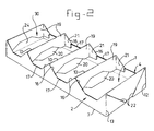
- Figure 2 shows a perspective view of a container produced from the first blank.
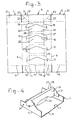
- Figure 3 shows a second blank.
- Figure 4 shows a detail of the container produced from the second blank.
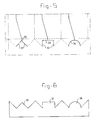
- Figure 5 shows further blank variants.
- Figure 6 shows the side of the container produced from the blank according to Figure 5.
- Figure 7 shows a blank for a container with a lid.
- Figure 8 shows the container with lid.
- Figure 9 shows the dies of the installation according to the invention, partially, in cross-section and in perspective.
- Figure 10 shows the various steps in the procedure.
- Figure 11 shows a variant of the installation with two lower dies.
- The blank shown in Figure 1 comprises five panels, that is to say a
first base panel 1, afirst side panel 2, asecond side panel 4, apanel 3 located between them, and asecond base panel 5. Said panels are joined to one another by means oflongitudinal fold lines - Furthermore, the blank comprises a number of
transverse fold lines transverse fold lines 11 are located at the extremities of the blank and intersect the longitudinal fold lines in such a way that they are also present in theside panels 2, 4 (transversefold line sections 12, 13) and thebase panels 1, 5 (transversefold line sections 14, 15).Cuts 23 are provided in the extension of thelongitudinal fold lines - The side regions which are located between, in each case, a transverse
fold line section longitudinal fold line cut 23 each have anoblique fold line 22. - A single
oblique fold line 16 adjoins the point of intersection between eachlongitudinal fold line transverse fold line 11; two oblique single fold lines 16, which run at opposite angles, adjoin in each case the point of intersection between eachlongitudinal fold line transverse fold line 10. - A
cut 17, which intersects the end of atransverse cut 18 running transversely to thelongitudinal fold lines transverse cut 18 is of gable shape, as a result of which relativelylarge regions 20 are formed on the one side and relativelysmall regions 19 are formed on the other side of each cut 18. - When producing a container, as shown in Figure 2, from the blank according to Figure 1, the
side panels fold lines side regions 21, which are delimited bylongitudinal fold line oblique fold line 16 andlongitudinal cut 17, are likewise folded such that they come to lie against the remaining part of the side panel concerned. At the same time, theregions transverse fold line 10. - The finished container is shown in Figure 2. The two
base panels oblique fold lines 22 are located are folded about saidfold line 22, as can be seen in Figure 2. - The base flaps 24 located outside the transverse
fold line sections region 19 folded about thetransverse fold line 11 and theregion 25; at the other side of the container, said base flaps 24 are located between theregion 20 andregion 25. - The blank shown in Figures 3 and 4 substantially corresponds to that in Figure 1. Contrary to the blank according to Figure 1, two
fold lines transverse cuts 18. When producing the container from the blank according to Figure 3, theregions bridge section 28 is located between them, which bridge section is delimited by, in each case, twofold lines compartments 30 has a greater strength and rigidity. - Although the blanks according to the figures both relate to a container having four compartments, the invention can be employed in the case of a container having different numbers of compartments as well.
- The blank (partially) shown in Figure 5 produces a container which has a side as shown in the side view in Figure 6. In this case the
respective protrusions incisions - Figure 7 shows a blank having
panels panel 53, which is joined via a fold line to thepanel 1 forming the base, comes to lie againstside panel 4, whilstpanel 54 comes to lie above the transverse partitions, as shown in Figure 8. - Figure 9 shows, diagrammatically, the
upper die 40, consisting of threepressing punches plate 43 indicated by broken lines. - A
lower die 44 is also present, which lower die consists ofdie sections 45 running in the longitudinal direction and diesections - Thin lines indicate the positions at which the pressing punches come into contact with the blank. In Figure 9 the blank is shown in its initially shaped state, which is achieved when the blank 1 is lying on those
die sections 45 of thelower die 44 which run in the longitudinal direction and thepressing punches die sections 45 running in the longitudinal direction. - As the saddle roof-shaped side of the die pairs 46, 47 running in the transverse direction, and in particular the
top surfaces 49 thereof, are at a higher level than the top ofdie sections 45 running in the longitudinal direction, theregions cuts panels panel 3, whilst pushing open of theregions panels panel 3, said panels then lying against the inside of thedie sections 45 running in the longitudinal direction. Theregions die sections - The abovementioned procedural steps are shown diagrammatically in Figure 10. First of all the blank according to Figures 7 and 8 is shown, with its various fold and cut lines. The
supplementary panel 52, for forming a lid closure, has been added. - In the first procedural step, carried out by means of the
upper die 40 andlower die 44, according to Figure 9, thepanels panel 3, thetransverse partitions - In the subsequent procedural step, the
panels - The supplementary
side wall panel 50 is then folded onto theside wall panel 4, after which thelid panel 51 is folded over the transverse partitions. Finally, theclosure panel 52 is folded over as far asside panel 2 and, if desired, fixed with glue. It will be clear that in Figure 10 an upside down container has been obtained. - The variant of the installation shown in Figure 11 comprises two lower dies 44, 53, mounted on a
carrier 54, which lower dies define two stations where different operations take place. In the first procedural step of Figure 10, the blank has just been shaped on the first lower die 44 to give the intermediate product with foldedsides transverse partitions panels procedural step 2 of Figure 10. - The
carrier 54 with the lower dies 44, 53 is movable both in the horizontal direction and in the vertical direction (see the arrows). There is a product on both lower dies. The carrier moves the products to the following station; after the products have been formed on lower dies 44, 53, they are moved to the right. The blank onlower die 44 is then shaped to give a container by folding over its base panels. At that point in time the container has become a coherent whole, so that thelower die 44, with carrier, can be moved away downwards out of the finished container. The carrier then moves to the left and then upwards. Lower die 44 comes into position beneath a blank to be processed, which has been fed in in the interim, and beneath the upper die 40 (which is not shown in Figure 11).Die 53 comes into position inside the finished container and on the following stroke to the right said finished container is discharged.
Claims (24)
- Blank for the production of a container divided into compartments, for example for biscuits, chocolates and the like, comprising at least four panels joined by parallel longitudinal fold lines (6-9), which panels (1-5) in the finished container define, successively, a base (1, 5), a side (2), a number of transverse partitions and a side (5), of which panels the three panels (2-4) defined by the sides (2, 4) and the panel (3) located between them possess a number of parallel transverse cuts (18) which intersect the longitudinal fold lines (7, 8) which join said three panels (2-4), and of which panels the intermediate panel (3) possesses a number of transverse fold lines (10, 11) running to the longitudinal fold lines (7, 8) delimiting it, and the side panels (2, 4) possess oblique fold lines (16) running from the point of intersection of a longitudinal fold line (7, 8) with a transverse fold line (10, 26, 27), such that when the panels (2, 4) defined by the sides are folded with respect to the intermediate panel (3), the regions (19, 20) of the intermediate panel (3) which in each case are delimited between a transverse fold line (10, 26, 27), two oblique fold lines (16) and a cut (18) are folded with the formation of transverse partitions which define the compartments (30), characterised in that both ends of each transverse cut (18) intersect an auxiliary cut (17, 31-34), the two ends of which adjoin an oblique fold line (16).
- Blank according to Claim 1, wherein the transverse cuts (18) have a gabled or arched shape at the location of the intermediate panel (3), such that the regions (19, 20) on either side of each transverse cut (18) have unequal dimensions, viewed in the direction parallel to the longitudinal fold lines (7, 8).
- Blank according to Claim 1 or 2, wherein both panels (2, 4) defining a side are joined via a fold line (6, 9) with a panel (1, 5) defining a base.
- Blank according to Claim 1, 2 or 3, wherein the intermediate panel (3) has a section (25) defining an end wall beyond each of the two outer transverse fold lines (11).
- Blank according to Claim 4, wherein the two outer transverse fold lines (11) extend over the entire two panels (2, 4) defining a side and the side regions (31) located beyond the two outer transverse fold lines (11) are joined via a longitudinal fold line (7, 8) to an end wall section (25), which side regions (31) are not joined to a panel (1, 5) defining a base and have an oblique fold line (22) running from the point of intersection between an outer transverse fold line (11) and a longitudinal fold line (7, 8) on one side and the free corner of said side region (31) on the other side.
- Blank according to Claim 4 or 5, wherein each base (1, 5) has, at both longitudinal ends, a transverse fold line (14, 15) located in the extension of, in each case, an outer transverse fold line (11), each of which determines an end base section (24), which end base sections (24) can be accommodated between an end wall section (25) and that region (19 and 20 respectively) of the intermediate panel (3) which is joined thereto via a transverse fold line.
- Blank according to one of the preceding claims, wherein, in each case, a number of pairs of transverse fold lines (26, 27) is provided in the intermediate panel (3), which pairs each enclose a bridge (28) which is joined at both ends via a longitudinal fold line (7, 8) to a panel (2, 4) defining a side.
- Blank according to one of the preceding claims, wherein each auxiliary cut (17) runs in the longitudinal direction and intersects the transverse cut at an essentially right angle.
- Blank according to one of Claims 1-7, wherein each auxiliary cut comprises two oblique cut halves (31) which intersect one another and the associated transverse cut at a common point of intersection (35).
- Blank according to one of Claims 1-7, wherein each auxiliary cut has a cut mid section (33) which runs in the longitudinal direction and intersects the associated transverse cut (17) at an essentially right angle, a cut transverse section (32) adjoining each of the two ends of said cut mid section.
- Blank according to one of Claims 1-7, wherein each auxiliary cut is arc-shaped (34) and intersects the associated transverse cut essentially half way along the length of its arc.
- Blank according to one of the preceding claims, wherein a panel (1, 5) forming the base is joined via a fold line to a lid (53, 54) which is foldable onto the transverse partitions defined by the transverse fold lines (10, 26, 27).
- Blank according to Claim 12, wherein the lid comprises a first lid panel (51) joined via a fold line to a panel (1, 5) forming the base, the width of which first lid panel (51) is essentially equal to the distance between the top of the transverse partitions and the base, and a second lid panel (52) joined via a further fold line to the first lid panel (51).
- Blank according to Claim 13, wherein the width of the second lid panel (52) is essentially equal to the width of the base.
- Installation for the production of a container from a blank according to one of the preceding claims, comprising:feed means for feeding a piece of starting material in sheet form,cutting and pressing means for making cuts and fold lines in the starting material in order to produce the blank, anddie means for folding the panels of the blank which in the finished container form the sides, as well as for folding the regions in the panel located between the sides in order to form the transverse partitions.
- Installation according to Claim 15, wherein the die means comprise an upper die and a lower die which are movable towards and away from one another, which lower die has two upright die sections running in the longitudinal direction, between which a number of transverse upright die sections positioned some distance apart are located, the number of said transverse die sections being equal to the number of transverse partitions to be formed, and which upper die has a number of transverse pressing punches, which pressing punches overlap the upright die sections of the lower die when the lower die and upper die are in the position in which they are moved towards one another.
- Installation according to Claim 16, wherein the number of pressing punches is equal to the number of transverse partitions plus one, which pressing punches are located alongside and between the upright transverse die sections when the lower die and upper die are in the position in which they are moved towards one another.
- Installation according to Claim 16 or 17, wherein the die sections running transversely have a saddle roof-shaped top and their dimension transverse to the saddle roof shape is virtually identical to the distance between two transverse partitions in the finished container.
- Installation according to one of Claims 16 - 18, wherein the upper limit of the transverse die sections is at a higher level than that of the die sections running in the longitudinal direction.
- Installation according to one of Claims 16 - 19, wherein the lower die is movable in the longitudinal direction for moving, after folding of the side walls and the transverse partitions, to a station provided with means for folding the panels forming the base of the container.
- Installation according to Claim 20, wherein the lower die is movable up and down for downward removal of the lower die from the container after formation of the base in the relevant station and for returning and moving upwards into its position beneath the upper die for receiving a subsequent blank.
- Installation according to Claim 21, wherein two lower dies are provided, the first of which has an outermost position at the location of the upper die and the other of which has an outermost position at the location of the station for forming the base.
- Method for producing a container from a blank according to one of Claims 1 - 11, by means of an installation according to one of Claims 16-22, comprising the following steps:feeding a piece of starting material in sheet form,making cuts and fold lines in the starting material to form a blank,placing the blank between the upper die and the lower die, andmoving the upper die and the lower die towards one another, wherein, in a first stage, the pressing punches push the blank onto the transverse die sections and the transverse die sections push open the cuts in the blank, and in a second, immediately consecutive stage the die sections running in the longitudinal direction fold the panels forming the sides whilst at the same time the cuts are pushed further open.
- Method according to Claim 23, wherein the lower die, with blank, is moved to a station for folding the panel (panels) forming the base.
Applications Claiming Priority (2)
| Application Number | Priority Date | Filing Date | Title |
|---|---|---|---|
| NL9500402 | 1995-03-01 | ||
| NL9500402A NL9500402A (en) | 1995-03-01 | 1995-03-01 | Blank for manufacturing a container, as well as a container made from such a blank. |
Publications (3)
| Publication Number | Publication Date |
|---|---|
| EP0729893A2 true EP0729893A2 (en) | 1996-09-04 |
| EP0729893A3 EP0729893A3 (en) | 1996-09-11 |
| EP0729893B1 EP0729893B1 (en) | 2001-06-13 |
Family
ID=19865659
Family Applications (1)
| Application Number | Title | Priority Date | Filing Date |
|---|---|---|---|
| EP19960200552 Expired - Lifetime EP0729893B1 (en) | 1995-03-01 | 1996-03-01 | Blank for a tray having partitions |
Country Status (4)
| Country | Link |
|---|---|
| EP (1) | EP0729893B1 (en) |
| DE (2) | DE29517449U1 (en) |
| HK (1) | HK1011008A1 (en) |
| NL (1) | NL9500402A (en) |
Cited By (6)
| Publication number | Priority date | Publication date | Assignee | Title |
|---|---|---|---|---|
| EP0905032A1 (en) * | 1997-09-09 | 1999-03-31 | Nederlandse Pillo-Pak Maatschappij B.V. | Blank and container therefrom as well as manufacturing apparatus therefor |
| EP0857656A3 (en) * | 1997-02-06 | 1999-06-09 | Profanters Backstube des Helmuth Profanter & Co. OHG | Device, especially for transport and presentation of an article |
| EP1842778A1 (en) * | 2006-04-05 | 2007-10-10 | Dividella AG | Packaging element, in particular packaging insert |
| EP2487115A1 (en) * | 2011-02-11 | 2012-08-15 | PilloPak b.v. | Blank, container, method and machine |
| EP2455218A3 (en) * | 2010-10-04 | 2013-05-08 | PilloPak b.v. | Blank, container, method and machine |
| JP2020132184A (en) * | 2019-02-15 | 2020-08-31 | 朝日印刷株式会社 | Tray and packaging box |
Families Citing this family (1)
| Publication number | Priority date | Publication date | Assignee | Title |
|---|---|---|---|---|
| DE102015216600B4 (en) * | 2015-08-31 | 2017-05-04 | Karl Knauer Kg | Folding box for receiving rounded objects, folding carton blank for a folding box and method for forming the folding box |
Citations (10)
| Publication number | Priority date | Publication date | Assignee | Title |
|---|---|---|---|---|
| US2164436A (en) * | 1938-03-31 | 1939-07-04 | Marshall A Waters | Box blanking machine |
| US2366557A (en) * | 1944-01-10 | 1945-01-02 | Zumbiel C W Co | Cellular paperboard container |
| US2407781A (en) * | 1943-08-30 | 1946-09-17 | Waldorf Paper Prod Co | Method and apparatus for sealing cartons |
| US2635512A (en) * | 1951-01-31 | 1953-04-21 | Clybourn Machine Corp | Machine for making fibrous boxes |
| US2744675A (en) * | 1952-04-23 | 1956-05-08 | Allied Plastics Co | Shipping container |
| US2815700A (en) * | 1954-10-25 | 1957-12-10 | Alford Cartons | Jig |
| US2970738A (en) * | 1959-11-16 | 1961-02-07 | John Strange Carton Company | Sectioned container and blank therefor |
| US3318204A (en) * | 1964-03-09 | 1967-05-09 | Allied Plastics Co | Machine for and method of forming produce trays |
| US4371366A (en) * | 1980-12-22 | 1983-02-01 | Owens-Illinois, Inc. | Method for making a produce tray |
| US4913339A (en) * | 1989-08-18 | 1990-04-03 | International Paper Company | Tray holder for liter bottles |
-
1995
- 1995-03-01 NL NL9500402A patent/NL9500402A/en not_active Application Discontinuation
- 1995-11-03 DE DE29517449U patent/DE29517449U1/en not_active Expired - Lifetime
-
1996
- 1996-03-01 DE DE1996613255 patent/DE69613255T2/en not_active Expired - Fee Related
- 1996-03-01 EP EP19960200552 patent/EP0729893B1/en not_active Expired - Lifetime
-
1998
- 1998-11-23 HK HK98112210A patent/HK1011008A1/en not_active IP Right Cessation
Patent Citations (10)
| Publication number | Priority date | Publication date | Assignee | Title |
|---|---|---|---|---|
| US2164436A (en) * | 1938-03-31 | 1939-07-04 | Marshall A Waters | Box blanking machine |
| US2407781A (en) * | 1943-08-30 | 1946-09-17 | Waldorf Paper Prod Co | Method and apparatus for sealing cartons |
| US2366557A (en) * | 1944-01-10 | 1945-01-02 | Zumbiel C W Co | Cellular paperboard container |
| US2635512A (en) * | 1951-01-31 | 1953-04-21 | Clybourn Machine Corp | Machine for making fibrous boxes |
| US2744675A (en) * | 1952-04-23 | 1956-05-08 | Allied Plastics Co | Shipping container |
| US2815700A (en) * | 1954-10-25 | 1957-12-10 | Alford Cartons | Jig |
| US2970738A (en) * | 1959-11-16 | 1961-02-07 | John Strange Carton Company | Sectioned container and blank therefor |
| US3318204A (en) * | 1964-03-09 | 1967-05-09 | Allied Plastics Co | Machine for and method of forming produce trays |
| US4371366A (en) * | 1980-12-22 | 1983-02-01 | Owens-Illinois, Inc. | Method for making a produce tray |
| US4913339A (en) * | 1989-08-18 | 1990-04-03 | International Paper Company | Tray holder for liter bottles |
Cited By (8)
| Publication number | Priority date | Publication date | Assignee | Title |
|---|---|---|---|---|
| EP0857656A3 (en) * | 1997-02-06 | 1999-06-09 | Profanters Backstube des Helmuth Profanter & Co. OHG | Device, especially for transport and presentation of an article |
| EP0905032A1 (en) * | 1997-09-09 | 1999-03-31 | Nederlandse Pillo-Pak Maatschappij B.V. | Blank and container therefrom as well as manufacturing apparatus therefor |
| US6006983A (en) * | 1997-09-09 | 1999-12-28 | Nederlandse Pillo-Pak Maatschappij B.V. | Blank for producing a container and a container produced therefrom |
| EP1842778A1 (en) * | 2006-04-05 | 2007-10-10 | Dividella AG | Packaging element, in particular packaging insert |
| EP2455218A3 (en) * | 2010-10-04 | 2013-05-08 | PilloPak b.v. | Blank, container, method and machine |
| EP2487115A1 (en) * | 2011-02-11 | 2012-08-15 | PilloPak b.v. | Blank, container, method and machine |
| JP2020132184A (en) * | 2019-02-15 | 2020-08-31 | 朝日印刷株式会社 | Tray and packaging box |
| JP7258588B2 (en) | 2019-02-15 | 2023-04-17 | 朝日印刷株式会社 | trays and boxes |
Also Published As
| Publication number | Publication date |
|---|---|
| HK1011008A1 (en) | 1999-07-02 |
| NL9500402A (en) | 1996-10-01 |
| DE29517449U1 (en) | 1996-02-08 |
| DE69613255T2 (en) | 2001-10-11 |
| EP0729893B1 (en) | 2001-06-13 |
| DE69613255D1 (en) | 2001-07-19 |
| EP0729893A3 (en) | 1996-09-11 |
Similar Documents
| Publication | Publication Date | Title |
|---|---|---|
| US4282999A (en) | H-divider containers | |
| CA1109438A (en) | Packing container and a laminate for its manufacture | |
| US4722437A (en) | Package alignment system | |
| US4929223A (en) | Packaging alignment system | |
| CA1072503A (en) | Partitioned tray and method of making | |
| AU1448597A (en) | Set of blanks, box, process and machine for making a box from such a set of blanks | |
| FR2629012B1 (en) | PROCESS AND MACHINE FOR MAKING POLYGONAL SECTION CRATES IN SHEET MATERIAL AND CRATES THUS OBTAINED | |
| RU98116991A (en) | CARTON BOX FOR PACKING OF SMOKING PRODUCTS AND ITS PREPARATION | |
| CA2173004A1 (en) | Method for Manufacturing a Partitioned Paperboard Food Tray | |
| US20210331437A1 (en) | Machine for forming a container from a blank | |
| WO2004043658A3 (en) | Modular/configurable die for a rotary die cutter | |
| EP0729893B1 (en) | Blank for a tray having partitions | |
| EP1335867B1 (en) | Cigarette box with hinged lid | |
| US4795086A (en) | Gable-topped container | |
| US4945007A (en) | Blank of material in sheet form and partition made therefrom | |
| FR2690415B1 (en) | PACKAGING WITH POLYGONAL SECTION OF SHEET AND BLANK MATERIAL FOR THE PRODUCTION OF SUCH A PACKAGING. | |
| US4251022A (en) | Pack, in particular cuboid cigarette pack | |
| CA2278864C (en) | (tray) pack for a group of articles, and process and apparatus for producing the same | |
| FR2731382B1 (en) | PROCESS FOR MANUFACTURING A CORRUGATED CARDBOARD PACKAGING CONTAINING REINFORCEMENTS FOLLOWING ITS VERTICAL EDGES, AND PRE-CUT AND DISCHARGED BLANK SUITABLE FOR THIS PROCESS | |
| IE812084L (en) | Carton blank | |
| CA2016213A1 (en) | Web of material consisting of (pack) blanks connected to one another | |
| US4330290A (en) | Method of producing wrapping for cigarettes | |
| CN1652985A (en) | Container for tobacco articles and relative production method | |
| EP1986933B1 (en) | Improved hinge-lid container and blank | |
| WO1996015902A3 (en) | Process and folding blanks for the production of folded cartons |
Legal Events
| Date | Code | Title | Description |
|---|---|---|---|
| PUAI | Public reference made under article 153(3) epc to a published international application that has entered the european phase |
Free format text: ORIGINAL CODE: 0009012 |
|
| PUAL | Search report despatched |
Free format text: ORIGINAL CODE: 0009013 |
|
| AK | Designated contracting states |
Kind code of ref document: A2 Designated state(s): BE CH DE DK FR GB LI NL |
|
| AK | Designated contracting states |
Kind code of ref document: A3 Designated state(s): BE CH DE DK FR GB LI NL |
|
| 17P | Request for examination filed |
Effective date: 19970303 |
|
| 17Q | First examination report despatched |
Effective date: 19980831 |
|
| GRAG | Despatch of communication of intention to grant |
Free format text: ORIGINAL CODE: EPIDOS AGRA |
|
| GRAG | Despatch of communication of intention to grant |
Free format text: ORIGINAL CODE: EPIDOS AGRA |
|
| GRAH | Despatch of communication of intention to grant a patent |
Free format text: ORIGINAL CODE: EPIDOS IGRA |
|
| GRAH | Despatch of communication of intention to grant a patent |
Free format text: ORIGINAL CODE: EPIDOS IGRA |
|
| GRAA | (expected) grant |
Free format text: ORIGINAL CODE: 0009210 |
|
| AK | Designated contracting states |
Kind code of ref document: B1 Designated state(s): BE CH DE DK FR GB LI NL |
|
| PG25 | Lapsed in a contracting state [announced via postgrant information from national office to epo] |
Ref country code: NL Free format text: LAPSE BECAUSE OF FAILURE TO SUBMIT A TRANSLATION OF THE DESCRIPTION OR TO PAY THE FEE WITHIN THE PRESCRIBED TIME-LIMIT Effective date: 20010613 Ref country code: LI Free format text: LAPSE BECAUSE OF FAILURE TO SUBMIT A TRANSLATION OF THE DESCRIPTION OR TO PAY THE FEE WITHIN THE PRESCRIBED TIME-LIMIT Effective date: 20010613 Ref country code: CH Free format text: LAPSE BECAUSE OF FAILURE TO SUBMIT A TRANSLATION OF THE DESCRIPTION OR TO PAY THE FEE WITHIN THE PRESCRIBED TIME-LIMIT Effective date: 20010613 Ref country code: BE Free format text: LAPSE BECAUSE OF FAILURE TO SUBMIT A TRANSLATION OF THE DESCRIPTION OR TO PAY THE FEE WITHIN THE PRESCRIBED TIME-LIMIT Effective date: 20010613 |
|
| REF | Corresponds to: |
Ref document number: 69613255 Country of ref document: DE Date of ref document: 20010719 |
|
| PG25 | Lapsed in a contracting state [announced via postgrant information from national office to epo] |
Ref country code: DK Free format text: LAPSE BECAUSE OF FAILURE TO SUBMIT A TRANSLATION OF THE DESCRIPTION OR TO PAY THE FEE WITHIN THE PRESCRIBED TIME-LIMIT Effective date: 20010913 |
|
| ET | Fr: translation filed | ||
| NLV1 | Nl: lapsed or annulled due to failure to fulfill the requirements of art. 29p and 29m of the patents act | ||
| REG | Reference to a national code |
Ref country code: CH Ref legal event code: PL |
|
| REG | Reference to a national code |
Ref country code: GB Ref legal event code: IF02 |
|
| PLBE | No opposition filed within time limit |
Free format text: ORIGINAL CODE: 0009261 |
|
| STAA | Information on the status of an ep patent application or granted ep patent |
Free format text: STATUS: NO OPPOSITION FILED WITHIN TIME LIMIT |
|
| 26N | No opposition filed | ||
| REG | Reference to a national code |
Ref country code: FR Ref legal event code: CD Ref country code: FR Ref legal event code: CA |
|
| PGFP | Annual fee paid to national office [announced via postgrant information from national office to epo] |
Ref country code: GB Payment date: 20040226 Year of fee payment: 9 |
|
| PGFP | Annual fee paid to national office [announced via postgrant information from national office to epo] |
Ref country code: FR Payment date: 20040322 Year of fee payment: 9 |
|
| PGFP | Annual fee paid to national office [announced via postgrant information from national office to epo] |
Ref country code: DE Payment date: 20040413 Year of fee payment: 9 |
|
| PG25 | Lapsed in a contracting state [announced via postgrant information from national office to epo] |
Ref country code: GB Free format text: LAPSE BECAUSE OF NON-PAYMENT OF DUE FEES Effective date: 20050301 |
|
| PG25 | Lapsed in a contracting state [announced via postgrant information from national office to epo] |
Ref country code: DE Free format text: LAPSE BECAUSE OF NON-PAYMENT OF DUE FEES Effective date: 20051001 |
|
| GBPC | Gb: european patent ceased through non-payment of renewal fee |
Effective date: 20050301 |
|
| PG25 | Lapsed in a contracting state [announced via postgrant information from national office to epo] |
Ref country code: FR Free format text: LAPSE BECAUSE OF NON-PAYMENT OF DUE FEES Effective date: 20051130 |
|
| REG | Reference to a national code |
Ref country code: FR Ref legal event code: ST Effective date: 20051130 |