EP0729126A1 - Überwachungs- und Flugzeugnavigationsverfahren und -vorrichtung für Präzisionslandung - Google Patents
Überwachungs- und Flugzeugnavigationsverfahren und -vorrichtung für Präzisionslandung Download PDFInfo
- Publication number
- EP0729126A1 EP0729126A1 EP96400271A EP96400271A EP0729126A1 EP 0729126 A1 EP0729126 A1 EP 0729126A1 EP 96400271 A EP96400271 A EP 96400271A EP 96400271 A EP96400271 A EP 96400271A EP 0729126 A1 EP0729126 A1 EP 0729126A1
- Authority
- EP
- European Patent Office
- Prior art keywords
- vertical
- aircraft
- heading
- barometric
- ahrs
- Prior art date
- Legal status (The legal status is an assumption and is not a legal conclusion. Google has not performed a legal analysis and makes no representation as to the accuracy of the status listed.)
- Granted
Links
Images

Classifications
-
- G—PHYSICS
- G08—SIGNALLING
- G08G—TRAFFIC CONTROL SYSTEMS
- G08G5/00—Traffic control systems for aircraft, e.g. air-traffic control [ATC]
- G08G5/0017—Arrangements for implementing traffic-related aircraft activities, e.g. arrangements for generating, displaying, acquiring or managing traffic information
- G08G5/0021—Arrangements for implementing traffic-related aircraft activities, e.g. arrangements for generating, displaying, acquiring or managing traffic information located in the aircraft
-
- G—PHYSICS
- G01—MEASURING; TESTING
- G01C—MEASURING DISTANCES, LEVELS OR BEARINGS; SURVEYING; NAVIGATION; GYROSCOPIC INSTRUMENTS; PHOTOGRAMMETRY OR VIDEOGRAMMETRY
- G01C23/00—Combined instruments indicating more than one navigational value, e.g. for aircraft; Combined measuring devices for measuring two or more variables of movement, e.g. distance, speed or acceleration
- G01C23/005—Flight directors
-
- G—PHYSICS
- G05—CONTROLLING; REGULATING
- G05D—SYSTEMS FOR CONTROLLING OR REGULATING NON-ELECTRIC VARIABLES
- G05D1/00—Control of position, course or altitude of land, water, air, or space vehicles, e.g. automatic pilot
- G05D1/04—Control of altitude or depth
- G05D1/06—Rate of change of altitude or depth
- G05D1/0607—Rate of change of altitude or depth specially adapted for aircraft
- G05D1/0653—Rate of change of altitude or depth specially adapted for aircraft during a phase of take-off or landing
- G05D1/0676—Rate of change of altitude or depth specially adapted for aircraft during a phase of take-off or landing specially adapted for landing
-
- G—PHYSICS
- G08—SIGNALLING
- G08G—TRAFFIC CONTROL SYSTEMS
- G08G5/00—Traffic control systems for aircraft, e.g. air-traffic control [ATC]
- G08G5/02—Automatic approach or landing aids, i.e. systems in which flight data of incoming planes are processed to provide landing data
- G08G5/025—Navigation or guidance aids
Definitions
- the present invention relates to an improvement in the guidance, approach and landing of aircraft operating in category 2 or 3A according to the certification of recognized civil organizations such as the DGAC, the FAA or the JAA in order to make aircraft capable to operate in the immediately lower category 3A or 3B, at a lower cost.
- Aircraft operating in category 2 or 3A must have, on landing approach, a minimum vertical visibility or decision height DH (Decision Height) of 50 feet and a minimum horizontal visibility or runway visual range. 200 meters.
- DH Decision Height
- certification levels 2 or 3A are not enough for certain companies operating in meteorologically disadvantaged regions because compliance with the minimum visibility of these certification levels means that a significant proportion of flights must be diverted and leads to a significant shortfall.
- HUD Head Up Display
- GPS Global positioning System
- TSO C 129c1 an avionics standard
- This standard requires the GPS receiver to give in addition to the position coordinates: longitude, latitude and altitude the horizontal east-west, north-south and vertical speeds of the wearer.
- the object of the invention is to propose a solution at lower cost, making it possible to meet the needs of airlines wishing to lower their operating minima in the precision approach phase, from the certified category 2 or 3A to the immediately certified category lower 3A or 3B by means of a hybrid system based on an attitude and heading reference center at low cost AHRS, and a head-up viewfinder using, to develop the FPV ground speed vector to be displayed, the possibilities of a GPS receiver to the avionics standard, and avoiding the carrying of a central inertial class.
- It relates to an aircraft surveillance and guidance method for precision landing applied to an aircraft provided with an attitude and heading reference center AHRS which is equipped with a compass and which delivers, inter alia, the magnetic heading ⁇ m and the vertical acceleration a z , of an anemo-barometric unit ADC providing, among other things, the vertical barometric speed V zB , of a positioning receiver by GPS satellites with avionics standard delivering in addition to the coordinates position latitude, longitude and altitude, the east-west and north-south horizontal speeds V EO and V NS , and a head-up viewfinder on which is displayed an artificial horizon line and the ground speed vector FPV.
- This method consists in locating the end of the FPV ground speed vector on the head-up viewfinder by means of two angular coordinates, one vertical with a FPA (Flight Path Angle) slope referenced relative to the artificial horizon line and drawn from the relationship :
- FPA Arctg V zBI V EO 2 + V NS 2
- V zBI is the baro-inertial vertical speed resulting from a hybridization between the barometric vertical speed V zB delivered by the anemo-barometric unit ADC and the vertical acceleration a z delivered by the attitude and heading reference unit AHRS
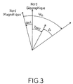
- the other horizontal of route ⁇ referenced with respect to the vertical median of the screen of the head-up viewfinder symbolizing the vertical longitudinal median plane of symmetry of the aircraft and drawn from the relation:
- ⁇ - ⁇ m + Arctg V EO V NS - decl where decl is the magnetic declination.
- the device further comprises a magnetic mass compensation circuit RMCU (Remote Magnetic Compensator Unit) which operates on the compass and which makes it possible to refine the measurement of magnetic heading by correcting the influence of the magnetic masses of the aircraft.
- RMCU Remote Magnetic Compensator Unit
- the GPS satellite positioning receiver also delivers information on the vertical speed of the aircraft which is compared with the information on the vertical speed of the aircraft deduced from measurements carried out by the attitude and heading reference center AHRS and by the ADC anemo-barometric unit to carry out a check of correct operation.
- the GPS satellite positioning receiver is provided with an integrity control device making it possible to ensure its availability both in the flight preparation phase and at the start of the approach for a landing.
- FIG. 1 shows a hybrid guidance system for an aircraft based on an autopilot and a head-up viewfinder making it possible to pass inexpensively from a certification level 2 or 3A to the certification level immediately below 3A or 3B.
- the pre-existing equipment constituting the basic equipment of an aircraft meeting a certification level 2 or 3A is the attitude and heading reference unit AHRS 1 without inertial platform, the compass 2 and the anemo-barometric unit ADC 3.
- the AHRS 1 attitude and heading reference unit is a low-cost device compared to an IRS inertial class unit which provides attitude and heading indications, and vertical acceleration.
- Compass 2 provides the magnetic heading to the attitude and heading reference center AHRS 1.
- the ADC 3 anemo-barometric control unit provides indications of altitude and vertical speed.
- the devices added for the passage to the immediately lower certification level are a GPS 4 satellite positioning receiver with avionics standard, a HUD 5 head-up viewfinder and its HUDC 6 computer, and an RMCU 7 magnetic mass compensator.
- the GPS 4 satellite positioning receiver has its justification in that it makes it very easy to locate and therefore to navigate a modern aircraft. There is no doubt that it will be part, in the short or medium term, of the basic navigation equipment of a modern aircraft. Moreover, there is now an avionics standard for GPS receivers (the TSO C 129c1).
- the GPS receiver in addition to the position in latitude, longitude and altitude, delivers the vertical and horizontal speeds east-west and north-south. It provides this information on an ARINC 429 type multi-receiver support so that it is not necessary to provide it with a specific output each time that it is intended to give it a new use.
- the head-up viewfinder 5 is of the conventional type. It consists of a semi-transparent plate through which the pilot sees the landscape and a projection system allowing symbols to be displayed on the semi-transparent plate so that they are seen by the pilot superimposed on the landscape.
- the main symbols displayed are, as can be seen in Figure 2, an airplane model 10, an artificial horizon line 11 graduated in heading scale 12 and a reticle 13 materializing in the form of a small winged circle the position from the end of the ground speed vector FPV.
- the airplane model 10 is fixed and placed on the longitudinal aircraft reference in the vertical longitudinal plane of symmetry of the aircraft. It makes it possible, in conjunction with the heading scale 12, which passes over the artificial horizon line 11 as a function of the heading followed, to assess the heading followed.
- the artificial horizon line 11 moves under the indications of the navigation system to coincide with the horizon line. She permits, in conjunction with the airplane model 10, to roughly assess the longitudinal and lateral attitude of the aircraft.
- the reticle 13 in the form of a small winged circle which materializes the position of the end of the ground speed vector FPV on the road and on a slope is mobile on the screen of the head-up viewfinder, its position in height above or below the artificial horizon line 11 depending on a slope angle FPA and its lateral offset relative to the median of the head-up viewfinder passing through the airplane model 10 depending on a route angle ⁇ both determined by the computer 6 of the head-up display.
- the computer 6 of the head-up viewfinder HUD determines the position of the artificial horizon line 11 and of the heading scale with which it is graduated from the indications of longitudinal and lateral attitude of the aircraft given by the central attitude reference and heading AHRS 1. It also determines the position of the reticle 13 locating the end of the ground speed vector. To do this, it calculates the slope angle FPA and the road angle ⁇ of the ground speed vector FPV.
- the vertical baro-inertial speed V zBI is conventionally obtained by hybridizing the barometric altitude Z B provided by the anemo-barometric unit ADC 3 and the vertical acceleration a z provided by the attitude and heading reference unit AHRS 1, this hybridization consisting in integrating the vertical acceleration a z in order to deduce therefrom an inertial vertical speed V I , and in combining this inertial vertical speed with the barometric altitude information Z B.
- the horizontal east-west and north-south speeds V EO and V NS are provided by the avionics standard GPS receiver.
- the relation (1) highlights the fact that the tangent of the slope angle FPA of the ground speed vector FPV with respect to the horizontal plane identified by the artificial horizon line 11 is equal to the ratio of the component vertical V zBI , at the horizontal component V EO 2 + V NS 2 of the ground speed vector FPV.
- the route angle of the ground speed vector FPV relative to the geographic north T RKv is given by the value of the arctangent of the ratio of the horizontal speed east-west V EO and the horizontal speed north-south V NS provided by the GPS receiver 4.
- the required level of security is achieved by making use of the redundancies existing between the information provided by the attitude and heading reference unit AHRS 1, the anemo-barometric unit ADC 3 and the positioning receiver by GPS satellites 4, in particular at the vertical speed information that is delivered by both the receiver of positioning by GPS 4 satellites and by the AHRS attitude and course reference center, and using a GPS satellite positioning receiver equipped with RAIM (Receiver Autonomous Integrity Monitoring) type devices allowing integrity control, prediction of availability or integrity of GPS information during the flight preparation phase and confirmation of availability or integrity of GPS information at the start of approach to a landing field.
- RAIM Receiveiver Autonomous Integrity Monitoring
Landscapes
- Engineering & Computer Science (AREA)
- Aviation & Aerospace Engineering (AREA)
- Radar, Positioning & Navigation (AREA)
- Remote Sensing (AREA)
- Physics & Mathematics (AREA)
- General Physics & Mathematics (AREA)
- Automation & Control Theory (AREA)
- Position Fixing By Use Of Radio Waves (AREA)
- Navigation (AREA)
- Traffic Control Systems (AREA)
Applications Claiming Priority (2)
| Application Number | Priority Date | Filing Date | Title |
|---|---|---|---|
| FR9501826A FR2730841B1 (fr) | 1995-02-17 | 1995-02-17 | Procede et dispositif de surveillance et de guidage d'aeronef pour atterrissage de precision |
| FR9501826 | 1995-02-17 |
Publications (2)
| Publication Number | Publication Date |
|---|---|
| EP0729126A1 true EP0729126A1 (de) | 1996-08-28 |
| EP0729126B1 EP0729126B1 (de) | 2000-09-27 |
Family
ID=9476239
Family Applications (1)
| Application Number | Title | Priority Date | Filing Date |
|---|---|---|---|
| EP96400271A Expired - Lifetime EP0729126B1 (de) | 1995-02-17 | 1996-02-09 | Überwachungs- und Flugzeugnavigationsverfahren und -vorrichtung für Präzisionslandung |
Country Status (7)
| Country | Link |
|---|---|
| US (1) | US5666111A (de) |
| EP (1) | EP0729126B1 (de) |
| JP (1) | JPH0976998A (de) |
| BR (1) | BR9600768A (de) |
| CA (1) | CA2169686C (de) |
| DE (1) | DE69610448T2 (de) |
| FR (1) | FR2730841B1 (de) |
Families Citing this family (27)
| Publication number | Priority date | Publication date | Assignee | Title |
|---|---|---|---|---|
| FR2743892B1 (fr) * | 1996-01-19 | 1998-02-13 | Sextant Avionique | Systeme d'aide au pilotage d'aeronefs a l'aide d'un viseur tete haute |
| US6064335A (en) * | 1997-07-21 | 2000-05-16 | Trimble Navigation Limited | GPS based augmented reality collision avoidance system |
| US5977884A (en) * | 1998-07-01 | 1999-11-02 | Ultradata Systems, Inc. | Radar detector responsive to vehicle speed |
| SE513291C2 (sv) | 1998-12-18 | 2000-08-21 | Ericsson Telefon Ab L M | Elektronisk kompass med kompensering för missvisning, förfarande för att kompensera missvisningen och radiokommunikationssystem för genomförande av förfarandet |
| AU6488400A (en) * | 1999-04-01 | 2000-11-10 | Ricardo A. Price | Electronic flight instrument displays |
| DE60016748T2 (de) * | 1999-05-14 | 2005-12-08 | Honeywell International Inc. | Verfahren und vorrichtung zur bestimmung der vertikalgeschwindigkeit eines flugzeugs |
| FR2815145B1 (fr) * | 2000-10-06 | 2003-10-31 | Sagem | Procede et systeme de navigation pour aeronef, notamment en phase d'approche |
| US6573841B2 (en) | 2001-04-02 | 2003-06-03 | Chelton Flight Systems Inc. | Glide range depiction for electronic flight instrument displays |
| US6693558B2 (en) * | 2001-06-18 | 2004-02-17 | Innovative Solutions & Support, Inc. | Aircraft flat panel display system |
| US6684157B2 (en) * | 2001-12-06 | 2004-01-27 | Yazaki North America, Inc. | Method and system for interfacing a global positioning system, other navigational equipment and wireless networks with a digital data network |
| FR2852689B1 (fr) * | 2003-03-20 | 2005-06-10 | Airbus France | Procede et indicateur pour afficher des informations illustrant des marges de vitesse sur un aeronef |
| US7251550B2 (en) * | 2003-10-01 | 2007-07-31 | Honeywell International Inc. | Aircraft accessory monitor |
| GB0424491D0 (en) * | 2004-11-05 | 2004-12-08 | Qinetiq Ltd | Airspace separation control and collision avoidance |
| US7501981B2 (en) * | 2005-11-18 | 2009-03-10 | Texas Instruments Incorporated | Methods and apparatus to detect and correct integrity failures in satellite positioning system receivers |
| FR2897840B1 (fr) | 2006-02-27 | 2009-02-13 | Eurocopter France | Procede et dispositif de traitement et de visualisation d'informations de pilotage d'un aeronef |
| FR2904706B1 (fr) * | 2006-08-02 | 2014-06-06 | Airbus France | Procede et dispositif pour determiner une hauteur de decision lors d'une approche autonome d'un aeronef. |
| US9189195B2 (en) * | 2006-10-16 | 2015-11-17 | Sandel Avionics, Inc. | Integrity monitoring |
| US8111920B2 (en) * | 2006-10-16 | 2012-02-07 | Sandel Avionics, Inc. | Closed-loop integrity monitor |
| KR101370241B1 (ko) * | 2006-10-20 | 2014-03-05 | 알레니아 아르마치 에스.피.에이. | 항공기 비행 파라미터들의 전자 디스플레이 장치 |
| US7948403B2 (en) * | 2007-12-04 | 2011-05-24 | Honeywell International Inc. | Apparatus and method for aligning an aircraft |
| KR20100070973A (ko) * | 2008-12-18 | 2010-06-28 | 박호철 | 헤드업 디스플레이 내비게이션 장치, 시스템 및 서비스 구현방법 |
| US9845734B2 (en) | 2011-04-20 | 2017-12-19 | Honeywell International Inc. | Air turbine start system with monopole starter air valve position |
| US8918234B2 (en) | 2012-09-17 | 2014-12-23 | Bell Helicopter Textron Inc. | Landing point indication system |
| CN106054909A (zh) * | 2016-06-28 | 2016-10-26 | 江苏中科院智能科学技术应用研究院 | 一种适用小型无人机的飞控设备 |
| CN107272740B (zh) * | 2017-07-28 | 2021-02-09 | 北京航天光华电子技术有限公司 | 一种新型四旋翼无人机控制系统 |
| CN114167888B (zh) * | 2021-11-19 | 2023-06-20 | 湖北航天技术研究院总体设计所 | 一种滑翔高超声速飞行器末端位置和速度控制方法 |
| CN114370869B (zh) * | 2021-12-24 | 2023-09-12 | 中国船舶重工集团公司七五0试验场 | 一种固定双桨驱动的无人水面艇自定位方法 |
Citations (6)
| Publication number | Priority date | Publication date | Assignee | Title |
|---|---|---|---|---|
| US4247843A (en) * | 1978-08-23 | 1981-01-27 | Sperry Corporation | Aircraft flight instrument display system |
| US4368517A (en) * | 1978-03-16 | 1983-01-11 | Bunker Ramo Corporation | Aircraft landing display system |
| US4454496A (en) * | 1980-10-30 | 1984-06-12 | Mcdonald Douglas Corporation | Conformal head-up display |
| JPH0260897A (ja) * | 1988-08-29 | 1990-03-01 | Mitsubishi Heavy Ind Ltd | 自動着陸装置 |
| EP0384993A2 (de) * | 1989-03-03 | 1990-09-05 | The Boeing Company | Automatische Rekonfiguration eines elektronischen Landeanzeigesystems |
| DE4140406A1 (de) * | 1991-12-07 | 1993-06-09 | Deutsche Aerospace Ag, 8000 Muenchen, De | System zur verbesserten orientierung, navigation, fuehrung und ueberwachung von flugzeugen |
Family Cites Families (5)
| Publication number | Priority date | Publication date | Assignee | Title |
|---|---|---|---|---|
| US3967799A (en) * | 1972-11-17 | 1976-07-06 | Sundstrand Data Control, Inc. | Head up display and pitch generator |
| US4104612A (en) * | 1977-02-03 | 1978-08-01 | Mcdonnell Douglas Corporation | Head-up display command bar generator |
| FR2487505A1 (fr) * | 1980-07-23 | 1982-01-29 | Dassault Avions | Dispositif d'assistance au pilotage d'un vehicule aerien |
| DE4109016C2 (de) * | 1991-03-20 | 1994-10-06 | Dornier Luftfahrt | Anzeigeinstrument für Luftfahrzeuge zur Darstellung der Fluglage, insbesondere der Roll- und Nicklage bzw. des Flugbahnwinkels |
| US5406489A (en) * | 1992-07-10 | 1995-04-11 | Unisys Corporation | Instrument for measuring an aircraft's roll, pitch, and heading by matching position changes along two sets of axes |
-
1995
- 1995-02-17 FR FR9501826A patent/FR2730841B1/fr not_active Expired - Fee Related
-
1996
- 1996-02-09 EP EP96400271A patent/EP0729126B1/de not_active Expired - Lifetime
- 1996-02-09 DE DE69610448T patent/DE69610448T2/de not_active Expired - Fee Related
- 1996-02-16 BR BR9600768A patent/BR9600768A/pt not_active Application Discontinuation
- 1996-02-16 CA CA002169686A patent/CA2169686C/fr not_active Expired - Fee Related
- 1996-02-16 US US08/603,084 patent/US5666111A/en not_active Expired - Lifetime
- 1996-02-19 JP JP8055491A patent/JPH0976998A/ja not_active Withdrawn
Patent Citations (6)
| Publication number | Priority date | Publication date | Assignee | Title |
|---|---|---|---|---|
| US4368517A (en) * | 1978-03-16 | 1983-01-11 | Bunker Ramo Corporation | Aircraft landing display system |
| US4247843A (en) * | 1978-08-23 | 1981-01-27 | Sperry Corporation | Aircraft flight instrument display system |
| US4454496A (en) * | 1980-10-30 | 1984-06-12 | Mcdonald Douglas Corporation | Conformal head-up display |
| JPH0260897A (ja) * | 1988-08-29 | 1990-03-01 | Mitsubishi Heavy Ind Ltd | 自動着陸装置 |
| EP0384993A2 (de) * | 1989-03-03 | 1990-09-05 | The Boeing Company | Automatische Rekonfiguration eines elektronischen Landeanzeigesystems |
| DE4140406A1 (de) * | 1991-12-07 | 1993-06-09 | Deutsche Aerospace Ag, 8000 Muenchen, De | System zur verbesserten orientierung, navigation, fuehrung und ueberwachung von flugzeugen |
Non-Patent Citations (1)
| Title |
|---|
| PATENT ABSTRACTS OF JAPAN vol. 014, no. 235 (M - 0975) 18 May 1990 (1990-05-18) * |
Also Published As
| Publication number | Publication date |
|---|---|
| JPH0976998A (ja) | 1997-03-25 |
| EP0729126B1 (de) | 2000-09-27 |
| BR9600768A (pt) | 1997-12-23 |
| FR2730841B1 (fr) | 1997-04-25 |
| DE69610448T2 (de) | 2001-06-28 |
| CA2169686A1 (fr) | 1996-08-18 |
| US5666111A (en) | 1997-09-09 |
| CA2169686C (fr) | 2009-06-30 |
| FR2730841A1 (fr) | 1996-08-23 |
| DE69610448D1 (de) | 2000-11-02 |
Similar Documents
| Publication | Publication Date | Title |
|---|---|---|
| EP0729126B1 (de) | Überwachungs- und Flugzeugnavigationsverfahren und -vorrichtung für Präzisionslandung | |
| US6157891A (en) | Positioning and ground proximity warning method and system thereof for vehicle | |
| CN103018761B (zh) | 向着陆跑道进场时确定飞行器位置信息的方法和系统 | |
| US9587960B2 (en) | System for piloting an aircraft, at least for piloting the aircraft during an autonomous approach for the purpose of landing | |
| US20070219678A1 (en) | Method of assisting in the navigation of an aircraft with an updating of the flight plan | |
| US10247573B1 (en) | Guidance system and method for low visibility takeoff | |
| FR2955562A1 (fr) | Procede et dispositif d'aide au pilotage d'un aeronef lors d'une phase finale d'approche | |
| US11852494B2 (en) | Restoring navigational performance for a navigational system | |
| US20190027048A1 (en) | Landing system for an aerial vehicle | |
| FR3038750A1 (fr) | Procede d'integration d'un nouveau service de navigation dans un systeme avionique embarque a architecture ouverte de type client-serveur, en particulier d'un service de manoeuvre fim | |
| CN104133256A (zh) | 在透视视图中图形显示天气灾害的系统和方法 | |
| US11353596B2 (en) | Position and motion informed navigation system | |
| CN108073178A (zh) | 用于航空器的平台进近的标准化 | |
| US9626873B2 (en) | Method, system and computer program for providing, on a human-machine interface, data relating to an aspect of the operation of an aircraft | |
| US9453921B1 (en) | Delayed-based geographic position data generation system, device, and method | |
| EP1464576A2 (de) | Verfahren und Einrichtung zur Steuerungshilfe eines Flugzeugs während der Landung | |
| FR2944634A1 (fr) | Procede de determination de la quantite de carburant emportee dans un aeronef permettant la tenue d'une contrainte de temps de type rta | |
| FR3043487A1 (fr) | Gestion de trajectoire d'un aeronef en cas de panne moteur | |
| FR3094084A1 (fr) | Systeme de calcul de mission d'un aeronef utilisant au moins une courbe d'iso-deplacement etendue et procede associe | |
| US20110022250A1 (en) | Helicopter autopilot | |
| FR3087042A1 (fr) | Gestion de systemes de gestion de vol asynchrones | |
| WO2002039138A1 (en) | Positioning and ground proximity warning method and system thereof for vehicle | |
| Weed et al. | GPS align in motion of civilian strapdown INS | |
| FR3035997A1 (fr) | Optimisation de la trajectoire d'un aeronef | |
| CN116380083A (zh) | 一种支持rnp运行的低成本航电系统航道偏差获取方法 |
Legal Events
| Date | Code | Title | Description |
|---|---|---|---|
| PUAI | Public reference made under article 153(3) epc to a published international application that has entered the european phase |
Free format text: ORIGINAL CODE: 0009012 |
|
| AK | Designated contracting states |
Kind code of ref document: A1 Designated state(s): DE GB IT NL |
|
| 17P | Request for examination filed |
Effective date: 19961001 |
|
| RAP1 | Party data changed (applicant data changed or rights of an application transferred) |
Owner name: THOMSON-CSF SEXTANT |
|
| GRAG | Despatch of communication of intention to grant |
Free format text: ORIGINAL CODE: EPIDOS AGRA |
|
| 17Q | First examination report despatched |
Effective date: 19991214 |
|
| GRAG | Despatch of communication of intention to grant |
Free format text: ORIGINAL CODE: EPIDOS AGRA |
|
| GRAH | Despatch of communication of intention to grant a patent |
Free format text: ORIGINAL CODE: EPIDOS IGRA |
|
| GRAH | Despatch of communication of intention to grant a patent |
Free format text: ORIGINAL CODE: EPIDOS IGRA |
|
| GRAA | (expected) grant |
Free format text: ORIGINAL CODE: 0009210 |
|
| AK | Designated contracting states |
Kind code of ref document: B1 Designated state(s): DE GB IT NL |
|
| REF | Corresponds to: |
Ref document number: 69610448 Country of ref document: DE Date of ref document: 20001102 |
|
| ITF | It: translation for a ep patent filed |
Owner name: JACOBACCI & PERANI S.P.A. |
|
| GBT | Gb: translation of ep patent filed (gb section 77(6)(a)/1977) |
Effective date: 20001206 |
|
| PLBE | No opposition filed within time limit |
Free format text: ORIGINAL CODE: 0009261 |
|
| STAA | Information on the status of an ep patent application or granted ep patent |
Free format text: STATUS: NO OPPOSITION FILED WITHIN TIME LIMIT |
|
| PG25 | Lapsed in a contracting state [announced via postgrant information from national office to epo] |
Ref country code: NL Free format text: LAPSE BECAUSE OF NON-PAYMENT OF DUE FEES Effective date: 20010901 |
|
| 26N | No opposition filed | ||
| NLV4 | Nl: lapsed or anulled due to non-payment of the annual fee |
Effective date: 20010901 |
|
| REG | Reference to a national code |
Ref country code: GB Ref legal event code: IF02 |
|
| PGFP | Annual fee paid to national office [announced via postgrant information from national office to epo] |
Ref country code: DE Payment date: 20050203 Year of fee payment: 10 |
|
| PG25 | Lapsed in a contracting state [announced via postgrant information from national office to epo] |
Ref country code: DE Free format text: LAPSE BECAUSE OF NON-PAYMENT OF DUE FEES Effective date: 20060901 |
|
| PGFP | Annual fee paid to national office [announced via postgrant information from national office to epo] |
Ref country code: IT Payment date: 20100220 Year of fee payment: 15 |
|
| PG25 | Lapsed in a contracting state [announced via postgrant information from national office to epo] |
Ref country code: IT Free format text: LAPSE BECAUSE OF NON-PAYMENT OF DUE FEES Effective date: 20110209 |
|
| PGFP | Annual fee paid to national office [announced via postgrant information from national office to epo] |
Ref country code: GB Payment date: 20120208 Year of fee payment: 17 |
|
| GBPC | Gb: european patent ceased through non-payment of renewal fee |
Effective date: 20130209 |
|
| PG25 | Lapsed in a contracting state [announced via postgrant information from national office to epo] |
Ref country code: GB Free format text: LAPSE BECAUSE OF NON-PAYMENT OF DUE FEES Effective date: 20130209 |