EP0729126A1 - Monitoring and aviation guidance method and device for precision landing - Google Patents
Monitoring and aviation guidance method and device for precision landing Download PDFInfo
- Publication number
- EP0729126A1 EP0729126A1 EP96400271A EP96400271A EP0729126A1 EP 0729126 A1 EP0729126 A1 EP 0729126A1 EP 96400271 A EP96400271 A EP 96400271A EP 96400271 A EP96400271 A EP 96400271A EP 0729126 A1 EP0729126 A1 EP 0729126A1
- Authority
- EP
- European Patent Office
- Prior art keywords
- vertical
- aircraft
- heading
- barometric
- ahrs
- Prior art date
- Legal status (The legal status is an assumption and is not a legal conclusion. Google has not performed a legal analysis and makes no representation as to the accuracy of the status listed.)
- Granted
Links
- 238000000034 method Methods 0.000 title claims description 7
- 238000012544 monitoring process Methods 0.000 title claims description 4
- 230000001133 acceleration Effects 0.000 claims abstract description 13
- 238000009396 hybridization Methods 0.000 claims description 5
- 240000007594 Oryza sativa Species 0.000 claims 1
- 235000007164 Oryza sativa Nutrition 0.000 claims 1
- 235000009566 rice Nutrition 0.000 claims 1
- 238000013459 approach Methods 0.000 description 6
- 101000797092 Mesorhizobium japonicum (strain LMG 29417 / CECT 9101 / MAFF 303099) Probable acetoacetate decarboxylase 3 Proteins 0.000 description 4
- 238000010586 diagram Methods 0.000 description 2
- 238000005259 measurement Methods 0.000 description 2
- 238000012790 confirmation Methods 0.000 description 1
- 230000010006 flight Effects 0.000 description 1
- 238000012986 modification Methods 0.000 description 1
- 230000004048 modification Effects 0.000 description 1
- 230000001105 regulatory effect Effects 0.000 description 1
- 230000000007 visual effect Effects 0.000 description 1
Images

Classifications
-
- G—PHYSICS
- G08—SIGNALLING
- G08G—TRAFFIC CONTROL SYSTEMS
- G08G5/00—Traffic control systems for aircraft, e.g. air-traffic control [ATC]
- G08G5/0017—Arrangements for implementing traffic-related aircraft activities, e.g. arrangements for generating, displaying, acquiring or managing traffic information
- G08G5/0021—Arrangements for implementing traffic-related aircraft activities, e.g. arrangements for generating, displaying, acquiring or managing traffic information located in the aircraft
-
- G—PHYSICS
- G01—MEASURING; TESTING
- G01C—MEASURING DISTANCES, LEVELS OR BEARINGS; SURVEYING; NAVIGATION; GYROSCOPIC INSTRUMENTS; PHOTOGRAMMETRY OR VIDEOGRAMMETRY
- G01C23/00—Combined instruments indicating more than one navigational value, e.g. for aircraft; Combined measuring devices for measuring two or more variables of movement, e.g. distance, speed or acceleration
- G01C23/005—Flight directors
-
- G—PHYSICS
- G05—CONTROLLING; REGULATING
- G05D—SYSTEMS FOR CONTROLLING OR REGULATING NON-ELECTRIC VARIABLES
- G05D1/00—Control of position, course, altitude or attitude of land, water, air or space vehicles, e.g. using automatic pilots
- G05D1/04—Control of altitude or depth
- G05D1/06—Rate of change of altitude or depth
- G05D1/0607—Rate of change of altitude or depth specially adapted for aircraft
- G05D1/0653—Rate of change of altitude or depth specially adapted for aircraft during a phase of take-off or landing
- G05D1/0676—Rate of change of altitude or depth specially adapted for aircraft during a phase of take-off or landing specially adapted for landing
-
- G—PHYSICS
- G08—SIGNALLING
- G08G—TRAFFIC CONTROL SYSTEMS
- G08G5/00—Traffic control systems for aircraft, e.g. air-traffic control [ATC]
- G08G5/02—Automatic approach or landing aids, i.e. systems in which flight data of incoming planes are processed to provide landing data
- G08G5/025—Navigation or guidance aids
Definitions
- the present invention relates to an improvement in the guidance, approach and landing of aircraft operating in category 2 or 3A according to the certification of recognized civil organizations such as the DGAC, the FAA or the JAA in order to make aircraft capable to operate in the immediately lower category 3A or 3B, at a lower cost.
- Aircraft operating in category 2 or 3A must have, on landing approach, a minimum vertical visibility or decision height DH (Decision Height) of 50 feet and a minimum horizontal visibility or runway visual range. 200 meters.
- DH Decision Height
- certification levels 2 or 3A are not enough for certain companies operating in meteorologically disadvantaged regions because compliance with the minimum visibility of these certification levels means that a significant proportion of flights must be diverted and leads to a significant shortfall.
- HUD Head Up Display
- GPS Global positioning System
- TSO C 129c1 an avionics standard
- This standard requires the GPS receiver to give in addition to the position coordinates: longitude, latitude and altitude the horizontal east-west, north-south and vertical speeds of the wearer.
- the object of the invention is to propose a solution at lower cost, making it possible to meet the needs of airlines wishing to lower their operating minima in the precision approach phase, from the certified category 2 or 3A to the immediately certified category lower 3A or 3B by means of a hybrid system based on an attitude and heading reference center at low cost AHRS, and a head-up viewfinder using, to develop the FPV ground speed vector to be displayed, the possibilities of a GPS receiver to the avionics standard, and avoiding the carrying of a central inertial class.
- It relates to an aircraft surveillance and guidance method for precision landing applied to an aircraft provided with an attitude and heading reference center AHRS which is equipped with a compass and which delivers, inter alia, the magnetic heading ⁇ m and the vertical acceleration a z , of an anemo-barometric unit ADC providing, among other things, the vertical barometric speed V zB , of a positioning receiver by GPS satellites with avionics standard delivering in addition to the coordinates position latitude, longitude and altitude, the east-west and north-south horizontal speeds V EO and V NS , and a head-up viewfinder on which is displayed an artificial horizon line and the ground speed vector FPV.
- This method consists in locating the end of the FPV ground speed vector on the head-up viewfinder by means of two angular coordinates, one vertical with a FPA (Flight Path Angle) slope referenced relative to the artificial horizon line and drawn from the relationship :
- FPA Arctg V zBI V EO 2 + V NS 2
- V zBI is the baro-inertial vertical speed resulting from a hybridization between the barometric vertical speed V zB delivered by the anemo-barometric unit ADC and the vertical acceleration a z delivered by the attitude and heading reference unit AHRS
- the other horizontal of route ⁇ referenced with respect to the vertical median of the screen of the head-up viewfinder symbolizing the vertical longitudinal median plane of symmetry of the aircraft and drawn from the relation:
- ⁇ - ⁇ m + Arctg V EO V NS - decl where decl is the magnetic declination.
- the device further comprises a magnetic mass compensation circuit RMCU (Remote Magnetic Compensator Unit) which operates on the compass and which makes it possible to refine the measurement of magnetic heading by correcting the influence of the magnetic masses of the aircraft.
- RMCU Remote Magnetic Compensator Unit
- the GPS satellite positioning receiver also delivers information on the vertical speed of the aircraft which is compared with the information on the vertical speed of the aircraft deduced from measurements carried out by the attitude and heading reference center AHRS and by the ADC anemo-barometric unit to carry out a check of correct operation.
- the GPS satellite positioning receiver is provided with an integrity control device making it possible to ensure its availability both in the flight preparation phase and at the start of the approach for a landing.
- FIG. 1 shows a hybrid guidance system for an aircraft based on an autopilot and a head-up viewfinder making it possible to pass inexpensively from a certification level 2 or 3A to the certification level immediately below 3A or 3B.
- the pre-existing equipment constituting the basic equipment of an aircraft meeting a certification level 2 or 3A is the attitude and heading reference unit AHRS 1 without inertial platform, the compass 2 and the anemo-barometric unit ADC 3.
- the AHRS 1 attitude and heading reference unit is a low-cost device compared to an IRS inertial class unit which provides attitude and heading indications, and vertical acceleration.
- Compass 2 provides the magnetic heading to the attitude and heading reference center AHRS 1.
- the ADC 3 anemo-barometric control unit provides indications of altitude and vertical speed.
- the devices added for the passage to the immediately lower certification level are a GPS 4 satellite positioning receiver with avionics standard, a HUD 5 head-up viewfinder and its HUDC 6 computer, and an RMCU 7 magnetic mass compensator.
- the GPS 4 satellite positioning receiver has its justification in that it makes it very easy to locate and therefore to navigate a modern aircraft. There is no doubt that it will be part, in the short or medium term, of the basic navigation equipment of a modern aircraft. Moreover, there is now an avionics standard for GPS receivers (the TSO C 129c1).
- the GPS receiver in addition to the position in latitude, longitude and altitude, delivers the vertical and horizontal speeds east-west and north-south. It provides this information on an ARINC 429 type multi-receiver support so that it is not necessary to provide it with a specific output each time that it is intended to give it a new use.
- the head-up viewfinder 5 is of the conventional type. It consists of a semi-transparent plate through which the pilot sees the landscape and a projection system allowing symbols to be displayed on the semi-transparent plate so that they are seen by the pilot superimposed on the landscape.
- the main symbols displayed are, as can be seen in Figure 2, an airplane model 10, an artificial horizon line 11 graduated in heading scale 12 and a reticle 13 materializing in the form of a small winged circle the position from the end of the ground speed vector FPV.
- the airplane model 10 is fixed and placed on the longitudinal aircraft reference in the vertical longitudinal plane of symmetry of the aircraft. It makes it possible, in conjunction with the heading scale 12, which passes over the artificial horizon line 11 as a function of the heading followed, to assess the heading followed.
- the artificial horizon line 11 moves under the indications of the navigation system to coincide with the horizon line. She permits, in conjunction with the airplane model 10, to roughly assess the longitudinal and lateral attitude of the aircraft.
- the reticle 13 in the form of a small winged circle which materializes the position of the end of the ground speed vector FPV on the road and on a slope is mobile on the screen of the head-up viewfinder, its position in height above or below the artificial horizon line 11 depending on a slope angle FPA and its lateral offset relative to the median of the head-up viewfinder passing through the airplane model 10 depending on a route angle ⁇ both determined by the computer 6 of the head-up display.
- the computer 6 of the head-up viewfinder HUD determines the position of the artificial horizon line 11 and of the heading scale with which it is graduated from the indications of longitudinal and lateral attitude of the aircraft given by the central attitude reference and heading AHRS 1. It also determines the position of the reticle 13 locating the end of the ground speed vector. To do this, it calculates the slope angle FPA and the road angle ⁇ of the ground speed vector FPV.
- the vertical baro-inertial speed V zBI is conventionally obtained by hybridizing the barometric altitude Z B provided by the anemo-barometric unit ADC 3 and the vertical acceleration a z provided by the attitude and heading reference unit AHRS 1, this hybridization consisting in integrating the vertical acceleration a z in order to deduce therefrom an inertial vertical speed V I , and in combining this inertial vertical speed with the barometric altitude information Z B.
- the horizontal east-west and north-south speeds V EO and V NS are provided by the avionics standard GPS receiver.
- the relation (1) highlights the fact that the tangent of the slope angle FPA of the ground speed vector FPV with respect to the horizontal plane identified by the artificial horizon line 11 is equal to the ratio of the component vertical V zBI , at the horizontal component V EO 2 + V NS 2 of the ground speed vector FPV.
- the route angle of the ground speed vector FPV relative to the geographic north T RKv is given by the value of the arctangent of the ratio of the horizontal speed east-west V EO and the horizontal speed north-south V NS provided by the GPS receiver 4.
- the required level of security is achieved by making use of the redundancies existing between the information provided by the attitude and heading reference unit AHRS 1, the anemo-barometric unit ADC 3 and the positioning receiver by GPS satellites 4, in particular at the vertical speed information that is delivered by both the receiver of positioning by GPS 4 satellites and by the AHRS attitude and course reference center, and using a GPS satellite positioning receiver equipped with RAIM (Receiver Autonomous Integrity Monitoring) type devices allowing integrity control, prediction of availability or integrity of GPS information during the flight preparation phase and confirmation of availability or integrity of GPS information at the start of approach to a landing field.
- RAIM Receiveiver Autonomous Integrity Monitoring
Landscapes
- Engineering & Computer Science (AREA)
- Aviation & Aerospace Engineering (AREA)
- Radar, Positioning & Navigation (AREA)
- Remote Sensing (AREA)
- Physics & Mathematics (AREA)
- General Physics & Mathematics (AREA)
- Automation & Control Theory (AREA)
- Position Fixing By Use Of Radio Waves (AREA)
- Navigation (AREA)
- Traffic Control Systems (AREA)
Abstract
Description
La présente invention concerne un perfectionnement au guidage, en approche et à l'atterrissage, d'aéronefs opérant en catégorie 2 ou 3A selon la certification d'organismes civils reconnus tels que la DGAC, la FAA ou le JAA afin de rendre les aéronefs aptes à opérer en catégorie immédiatement inférieure 3A ou 3B, cela à un moindre coût.The present invention relates to an improvement in the guidance, approach and landing of aircraft operating in
Les aéronefs opérant en catégorie 2 ou 3A doivent avoir, en approche à l'atterrissage, une visibilité verticale minimum ou hauteur de décision DH (Decision Height) de 50 pieds et une visibilité horizontale minimum ou portée visuelle de piste RVR (Runway Visual Range) de 200 mètres.Aircraft operating in
Ces limites de visibilité requises en catégorie 2 ou 3A sont adoptées pour des aéronefs équipés d'un pilote automatique contrôlé par une centrale anémo-barométrique ADC (Air Data Computer) fournissant l'altitude et la vitesse verticale, et par une centrale de référence de cap et d'assiette AHRS (Attitude Heading Reference System) sans plate-forme inertielle, associée à une boussole fournissant les assiettes longitudinale et transversale, les accélérations verticale et horizontales selon les trois axes, et le cap magnétique.These visibility limits required in
Malgré des performances déjà fort honorables les niveaux de certification 2 ou 3A, ne suffisent pas à certaines compagnies qui opèrent dans des contrées météorologiquement défavorisées car le respect des minima de visibilité de ces niveaux de certification oblige à dérouter une proportion non négligeable des vols et entraîne un manque à gagner important.Despite the already highly honorable performance,
En conséquence, il existe un réel besoin de pouvoir faire évoluer les équipements d'un aéronef certifiés en catégorie 2 ou 3A vers la catégorie de certification immédiatement inférieure 3A ou 3B pour réduire les minima de visibilité et permettre des approches à l'atterrissage dans des conditions de moindre visibilité.Consequently, there is a real need to be able to upgrade the equipment of an aircraft certified in
Une manière de faire est de changer le pilote automatique par un autre certifié en catégorie inférieure. Cette opération a l'inconvénient d'être coûteuse car elle peut impliquer le changement d'une centrale de référence d'attitude et de cap AHRS sans plate-forme inertielle par une centrale de classe inertielle type IRS (Inertial Reference System).One way to do this is to change the autopilot to another certified lower category. This operation has the disadvantage of being costly because it can involve the change of a reference unit attitude and heading AHRS without inertial platform by a central inertial class type IRS (Inertial Reference System).
Une autre manière de faire pour apporter le surcroît de performances nécessaire est d'ajouter, à l'équipement de guidage d'un aéronef certifié en catégorie 2 ou 3A, un viseur tête haute HUD (Head Up Display) pour constituer un système hybride. Cet ajout a l'avantage de pouvoir se faire sous la forme d'un kit de mise à niveau pouvant être approvisionné directement par les compagnies aériennes et de s'insérer de façon harmonieuse sans modification majeure de l'architecture du système existant.Another way of providing the additional performance required is to add, to the guidance equipment of an aircraft certified in
Les exigences pour la certification en catégories 3A et 3B des systèmes hybrides avec viseur tête haute sont réglementées par les autorités de certification (groupe JAR AWO et AC 120-28C FAR en particulier). Elles font apparaître de nouvelles contraintes qui sont celles de disposer d'informations de référence primaire de qualité supérieure et de nature différente à celles exigées strictement au titre de la catégorie déjà certifiée 2 ou 3A, donc pas nécessairement disponibles, comme par exemple, l'information de vitesse sol FPV (Flight Path Vector).The requirements for certification in categories 3A and 3B of hybrid systems with a head-up display are regulated by the certification authorities (JAR AWO group and AC 120-28C FAR in particular). They reveal new constraints which are those of having primary reference information of higher quality and of a different nature to those strictly required under the category already certified 2 or 3A, therefore not necessarily available, as for example, the ground speed information FPV (Flight Path Vector).
Il est donc nécessaire de proposer une source nouvelle d'élaboration de ces informations.It is therefore necessary to propose a new source for developing this information.
Ce problème est traditionnellement résolu par l'emport d'une centrale de classe inertielle type IRS ou par une mise à niveau AHRS/IRS impliquant pour la dernière solution une recertification du pilote automatique. Bien que techniquement satisfaisantes ces solutions présentent un intérêt économique médiocre étant donné le coût à l'achat et à la maintenance d'une centrale de classe inertielle.This problem is traditionally resolved by carrying a central inertial class type IRS or by upgrading AHRS / IRS implying for the last solution a recertification of the autopilot. Although technically satisfactory, these solutions are of poor economic interest given the cost of purchasing and maintaining an inertial class power station.
Par ailleurs, il est de plus en plus envisagé d'équiper les aéronefs de récepteur de positionnement par satellites GPS (Global positioning System) afin de faciliter leur localisation et leur navigation. Dans cette perspective, un standard avionique (le TSO C 129c1 ) a été récemment établi sur les caractéristiques minimales que doit présenter un récepteur GPS embarqué à bord d'un aéronef. Ce standard impose au récepteur GPS de donner en plus des coordonnées de position: longitude, latitude et altitude les vitesses horizontales est-ouest, nord-sud et verticale du porteur.Furthermore, it is increasingly envisaged to equip aircraft with GPS (Global positioning System) satellite positioning receivers in order to facilitate their location and navigation. In this perspective, an avionics standard (TSO C 129c1) has recently been established on the minimum characteristics that a GPS receiver on board an aircraft must have. This standard requires the GPS receiver to give in addition to the position coordinates: longitude, latitude and altitude the horizontal east-west, north-south and vertical speeds of the wearer.
Le but de l'invention est de proposer une solution à moindre coût, permettant de répondre aux besoins de compagnies aériennes voulant abaisser leur minima d'exploitation en phase d'approche de précision, de la catégorie certifiée 2 ou 3A vers la catégorie certifiée immédiatement inférieure 3A ou 3B au moyen d'un système hybride à base d'une centrale de référence d'attitude et de cap à bas coût AHRS, et d'un viseur tête haute utilisant, pour élaborer le vecteur vitesse sol FPV à afficher, les possibilités d'un récepteur GPS au standard avionique, et évitant l'emport d'une centrale de classe inertielle.The object of the invention is to propose a solution at lower cost, making it possible to meet the needs of airlines wishing to lower their operating minima in the precision approach phase, from the
Elle a pour objet un procédé de surveillance et de guidage d'aéronef pour atterrissage de précision appliqué à un aéronef pourvu d'une centrale de référence d'attitude et de cap AHRS qui est équipée d'une boussole et qui délivre, entre autres, le cap magnétique Ψm et l'accélération verticale az, d'une centrale anémo-barométrique ADC fournissant, entre autres, la vitesse verticale barométrique VzB, d'un récepteur de positionnement par satellites GPS au standard avionique délivrant en plus des coordonnées de position latitude, longitude et altitude, les vitesses horizontales est-ouest et nord-sud VEO et VNS, et d'un viseur tête haute sur lequel est affiché une ligne d'horizon artificiel et le vecteur vitesse sol FPV. Ce procédé consiste à situer l'extrémité du vecteur vitesse sol FPV sur le viseur tête haute au moyen de deux coordonnées angulaires, l'une verticale de pente FPA (Flight Path Angle) référencée par rapport à la ligne d'horizon artificielle et tirée de la relation :![]()
l'autre horizontale de route Δ référencée par rapport à la médiane verticale de l'écran du viseur tête haute symbolisant le plan vertical longitudinal médian de symétrie de l'aéronef et tirée de la relation :![]()
![]()
the other horizontal of route Δ referenced with respect to the vertical median of the screen of the head-up viewfinder symbolizing the vertical longitudinal median plane of symmetry of the aircraft and drawn from the relation: ![]()
Elle a également pour objet un dispositif de surveillance et de guidage d'aéronef mettant en oeuvre le procédé précité et comportant une centrale de référence d'attitude et de cap AHRS qui est équipée d'une boussole et qui délivre, entre autres, le cap magnétique Ψm et l'accélération verticale az, une centrale anémo-barométrique ADC fournissant, entre autres, la vitesse verticale barométrique VzB, un récepteur de positionnement par satellites GPS au standard avionique délivrant en plus des coordonnées de position latitude, longitude et altitude, les vitesses horizontales est-ouest et nord-sud VEO et VNS, un viseur tête haute sur lequel est affiché une ligne d'horizon artificiel et le vecteur vitesse sol FPV, et un calculateur de viseur tête haute équipé :
- de moyens de calcul de la coordonnée angulaire verticale de pente FPA (Flight Path Angle) de l'extrémité du vecteur vitesse sol FPV par rapport de la ligne d'horizon artificiel au moyen de la relation :

- de moyens de calcul de la coordonnée angulaire horizontale de route Δ de l'extrémité du vecteur vitesse sol FPV par rapport à la médiane verticale de l'écran du viseur tête haute symbolisant le plan vertical longitudinal médian de symétrie de l'aéronef au moyen de la relation :

- means for calculating the vertical angular coordinate of slope FPA (Flight Path Angle) of the end of the ground speed vector FPV relative to the artificial horizon line by means of the relation:
- means for calculating the horizontal angular route coordinate Δ of the end of the ground speed vector FPV relative to the vertical median of the head-up display screen symbolizing the vertical longitudinal median plane of symmetry of the aircraft by means of the relationship :
Avantageusement, le dispositif comporte en outre un circuit de compensation de masses magnétiques RMCU (Remote Magnetic Compensator Unit) qui opère sur la boussole et qui permet d'affiner la mesure de cap magnétique en corrigeant l'influence des masses magnétiques de l'aéronef.Advantageously, the device further comprises a magnetic mass compensation circuit RMCU (Remote Magnetic Compensator Unit) which operates on the compass and which makes it possible to refine the measurement of magnetic heading by correcting the influence of the magnetic masses of the aircraft.
Avantageusement, le récepteur de positionnement par satellites GPS délivre également une information de vitesse verticale de l'aéronef qui est comparée avec l'information de vitesse verticale de l'aéronef déduite de mesures effectuées par la centrale de référence d'attitude et de cap AHRS et par la centrale anémo-barométrique ADC pour réaliser un contrôle de bon fonctionnement.Advantageously, the GPS satellite positioning receiver also delivers information on the vertical speed of the aircraft which is compared with the information on the vertical speed of the aircraft deduced from measurements carried out by the attitude and heading reference center AHRS and by the ADC anemo-barometric unit to carry out a check of correct operation.
Avantageusement, le récepteur de positionnement par satellite GPS est pourvu d'un dispositif de contrôle d'intégrité permettant de s'assurer de sa disponibilité aussi bien en phase de préparation de vol qu'en début d'approche pour un atterrissage.Advantageously, the GPS satellite positioning receiver is provided with an integrity control device making it possible to ensure its availability both in the flight preparation phase and at the start of the approach for a landing.
D'autres caractéristiques et avantages de l'invention ressortiront de la description d'un mode de réalisation donné à titre d'exemple. Cette description sera faite ci-après en regard du dessin dans lequel :
- une figure 1 montre un schéma de principe d'un dispositif de guidage d'aéronef conforme à l'invention ;
- une figure 2 illustre les symboles principaux apparaissant sur l'écran d'un afficheur tête haute ; et
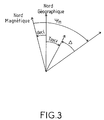
- une figure 3 est un schéma illustrant la façon dont est obtenue la coordonnée angulaire de route de l'extrémité du vecteur vitesse sol FPV.
- Figure 1 shows a block diagram of an aircraft guidance device according to the invention;
- FIG. 2 illustrates the main symbols appearing on the screen of a head-up display; and
- FIG. 3 is a diagram illustrating how the angular route coordinate of the end of the ground speed vector FPV is obtained.
La figure 1 montre un système hybride de guidage pour aéronef à base d'un pilote automatique et d'un viseur tête haute permettant de passer à moindre frais d'un niveau de certification 2 ou 3A au niveau de certification immédiatement inférieur 3A ou 3B. On y distingue deux sortes d'appareillages de guidage : une première sorte d'appareillages préexistants constituant les équipements de base d'un aéronef répondant à un niveau de certification 2 ou 3A et une deuxième sorte d'appareillages ajoutés pour passer au niveau de certification immédiatement inférieur 3A ou 3B.FIG. 1 shows a hybrid guidance system for an aircraft based on an autopilot and a head-up viewfinder making it possible to pass inexpensively from a
Les appareillages préexistants constituant les équipements de base d'un aéronef répondant à un niveau de certification 2 ou 3A sont la centrale de référence d'attitude et de cap AHRS 1 sans plate-forme inertielle, la boussole 2 et la centrale anémo-barométrique ADC 3.The pre-existing equipment constituting the basic equipment of an aircraft meeting a
La centrale de référence d'attitude et de cap AHRS 1 est un appareillage à bas coût par rapport à une centrale de classe inertielle IRS qui fournit des indications d'attitude et de cap, et l'accélération verticale.The AHRS 1 attitude and heading reference unit is a low-cost device compared to an IRS inertial class unit which provides attitude and heading indications, and vertical acceleration.
La boussole 2 fournit le cap magnétique à la centrale de référence d'attitude et de cap AHRS 1.
La centrale anémo-barométrique ADC 3 fournit des indications d'altitude et de vitesse verticale.The ADC 3 anemo-barometric control unit provides indications of altitude and vertical speed.
Les appareillages ajoutés pour le passage au niveau de certification immédiatement inférieur sont un récepteur de positionnement par satellites GPS 4 au standard avionique, un viseur tête haute HUD 5 et son calculateur HUDC 6, et un compensateur de masse magnétique RMCU 7.The devices added for the passage to the immediately lower certification level are a GPS 4 satellite positioning receiver with avionics standard, a
Le récepteur de positionnement par satellites GPS 4 a sa justification dans le fait qu'il apporte de grandes facilités à la localisation et par conséquent à la navigation d'un aéronef moderne. Il ne fait pas de doute qu'il fera partie, à court ou moyen terme, des équipements de navigation de base d'un aéronef moderne. D'ailleurs, il existe dés maintenant un standard avionique pour récepteur GPS (le TSO C 129c1 ). Le récepteur GPS, délivre, en plus de la position en latitude, longitude et altitude, les vitesses verticale et horizontales est-ouest et nord-sud. Il fournit ces informations sur un support multi-récepteur type ARINC 429 de sorte qu'il n'est pas nécessaire de lui prévoir une sortie spécifique à chaque fois que l'on envisage de lui donner une nouvelle utilisation.The GPS 4 satellite positioning receiver has its justification in that it makes it very easy to locate and therefore to navigate a modern aircraft. There is no doubt that it will be part, in the short or medium term, of the basic navigation equipment of a modern aircraft. Moreover, there is now an avionics standard for GPS receivers (the TSO C 129c1). The GPS receiver, in addition to the position in latitude, longitude and altitude, delivers the vertical and horizontal speeds east-west and north-south. It provides this information on an ARINC 429 type multi-receiver support so that it is not necessary to provide it with a specific output each time that it is intended to give it a new use.
Le viseur tête haute 5 est de type classique. Il est constitué d'une plaque semi-transparente à travers laquelle le pilote voit le paysage et d'un système de projection permettant d'afficher des symboles sur la plaque semi-transparente pour qu'ils soient vus par le pilote en superposition avec le paysage. Les principaux symboles affichés sont, comme on peut le voir sur la figure 2, une maquette avion 10 , une ligne d'horizon artificiel 11 graduée en échelle de cap 12 et un réticule 13 matérialisant sous la forme d'un petit cercle ailé la position de l'extrémité du vecteur vitesse sol FPV.The head-
La maquette avion 10 est fixe et placée sur la référence longitudinale aéronef dans le plan longitudinal vertical de symétrie de l'aéronef. Elle permet en liaison avec l'échelle de cap 12, qui défile sur la ligne d'horizon artificiel 11 en fonction du cap suivi, d'apprécier le cap suivi.The
La ligne d'horizon artificiel 11 se déplace sous les indications du système de navigation pour coïncider avec la ligne d'horizon. Elle permet, en liaison avec la maquette avion 10, d'apprécier, de manière grossière, les assiettes longitudinale et latérale de l'aéronef.The
Le réticule 13 en forme de petit cercle ailé qui matérialise la position de l'extrémité du vecteur vitesse sol FPV en route et en pente est mobile sur l'écran du viseur tête haute, sa position en hauteur au-dessus ou au-dessous de la ligne d'horizon artificielle 11 dépendant d'un angle de pente FPA et son décalage latéral par rapport à la médiane du viseur tête haute passant par la maquette avion 10 dépendant d'un angle de route Δ déterminés l'un et l'autre par le calculateur 6 du viseur tête haute.The
Le calculateur 6 du viseur tête haute HUD détermine la position de la ligne d'horizon artificielle 11 et de l'échelle de cap avec laquelle elle est graduée à partir des indications d'assiettes longitudinale et latérale de l'aéronef données par la centrale de référence d'attitude et cap AHRS 1. Il détermine aussi la position du réticule 13 repérant l'extrémité du vecteur vitesse sol. Pour ce faire, il calcule l'angle de pente FPA et l'angle de route Δ du vecteur vitesse sol FPV.The
Pour le calcul de l'angle de pente du vecteur vitesse sol il procède à partir de la vitesse verticale baro-inertielle VzBI et des vitesses horizontales est-ouest et nord-sud VEO et VNS par mise en oeuvre de la relation :![]()
![]()
La relation (1) met en avant le fait que la tangente de l'angle de pente FPA du vecteur vitesse sol FPV par rapport au plan horizontal repéré par la ligne d'horizon artificielle 11 est égale au rapport de la composante verticale VzBI, à la composante horizontale![]()
![]()
Pour le calcul de l'angle de route Δ du vecteur vitesse sol FPV le calculateur 6 du viseur tête haute procède à partir du cap magnétique Ψm fourni par la centrale de référence d'attitude et de cap AHRS 1, de l'angle de route vraie par rapport au nord géographique ArctgV EO /V NS déduit des vitesses horizontales sol VEO et VNS délivrées par le récepteur GPS 4, et d'une déclinaison magnétique decl tirée d'une table adressée au moyen de la localisation faite par le récepteur GPS 4, par mise en oeuvre de la relation :![]()
![]()
Pour procurer une précision globale satisfaisant les niveaux requis par les opérations en catégorie 3A ou 3B, on fait appel à une table précise de déclinaison magnétique dans laquelle on se repère grâce à la localisation procurée par le récepteur GPS 4 et à une information de cap magnétique Ψm compensée au moyen d'un dispositif de compensation de masses magnétiques RMCU 7 équipant la boussole.To obtain an overall precision satisfying the levels required by operations in category 3A or 3B, use is made of a precise magnetic declination table in which one can locate oneself thanks to the location provided by the GPS receiver 4 and to magnetic heading information. Ψ m compensated by means of a
Le niveau de sécurité requis est atteint en faisant appel aux redondances existant entre les informations fournies par la centrale de référence d'attitude et de cap AHRS 1, la centrale anémo-barométrique ADC 3 et le récepteur de positionnement par satellites GPS 4, notamment à l'information de vitesse verticale qui est délivrée à la fois par le récepteur de positionnement par satellites GPS 4 et par la centrale de référence d'attitude et de cap AHRS, et en utilisant un récepteur de positionnement par satellites GPS équipé de dispositifs de type RAIM (Receiver Autonomous Integrity Monitoring) permettant un contrôle de l'intégrité, une prédiction de disponibilité ou d'intégrité des informations GPS en phase de préparation de vol et une confirmation de disponibilité ou d'intégrité des informations GPS en début d'approche d'un terrain d'atterrissage.The required level of security is achieved by making use of the redundancies existing between the information provided by the attitude and heading reference unit AHRS 1, the anemo-
Bien entendu, la présente invention n'est pas limitée au mode de réalisation décrit et représenté mais est susceptible de nombreuses variantes accessibles à l'homme de l'art sans que l'on s'écarte de l'esprit de l'invention.Of course, the present invention is not limited to the embodiment described and shown but is capable of numerous variants accessible to those skilled in the art without departing from the spirit of the invention.
Claims (7)
l'autre horizontale d'angle de route Δ référencée par rapport à la médiane verticale (14) de l'écran du viseur tête haute symbolisant le plan longitudinal vertical de symétrie de l'aéronef et tirée de la relation :
the other horizontal course angle Δ referenced with respect to the vertical median (14) of the screen of the head-up viewfinder symbolizing the vertical longitudinal plane of symmetry of the aircraft and drawn from the relationship:
Applications Claiming Priority (2)
| Application Number | Priority Date | Filing Date | Title |
|---|---|---|---|
| FR9501826A FR2730841B1 (en) | 1995-02-17 | 1995-02-17 | AIRCRAFT MONITORING AND GUIDANCE METHOD AND DEVICE FOR PRECISION LANDING |
| FR9501826 | 1995-02-17 |
Publications (2)
| Publication Number | Publication Date |
|---|---|
| EP0729126A1 true EP0729126A1 (en) | 1996-08-28 |
| EP0729126B1 EP0729126B1 (en) | 2000-09-27 |
Family
ID=9476239
Family Applications (1)
| Application Number | Title | Priority Date | Filing Date |
|---|---|---|---|
| EP96400271A Expired - Lifetime EP0729126B1 (en) | 1995-02-17 | 1996-02-09 | Monitoring and aviation guidance method and device for precision landing |
Country Status (7)
| Country | Link |
|---|---|
| US (1) | US5666111A (en) |
| EP (1) | EP0729126B1 (en) |
| JP (1) | JPH0976998A (en) |
| BR (1) | BR9600768A (en) |
| CA (1) | CA2169686C (en) |
| DE (1) | DE69610448T2 (en) |
| FR (1) | FR2730841B1 (en) |
Families Citing this family (27)
| Publication number | Priority date | Publication date | Assignee | Title |
|---|---|---|---|---|
| FR2743892B1 (en) * | 1996-01-19 | 1998-02-13 | Sextant Avionique | AIRCRAFT HANDLING ASSISTANCE SYSTEM USING A HEADSET VIEWER |
| US6064335A (en) * | 1997-07-21 | 2000-05-16 | Trimble Navigation Limited | GPS based augmented reality collision avoidance system |
| US5977884A (en) * | 1998-07-01 | 1999-11-02 | Ultradata Systems, Inc. | Radar detector responsive to vehicle speed |
| SE513291C2 (en) | 1998-12-18 | 2000-08-21 | Ericsson Telefon Ab L M | Electronic compass with offset compensation, method of offsetting offset and radio communication system for carrying out the procedure |
| AU6488400A (en) * | 1999-04-01 | 2000-11-10 | Ricardo A. Price | Electronic flight instrument displays |
| DE60016748T2 (en) * | 1999-05-14 | 2005-12-08 | Honeywell International Inc. | METHOD AND DEVICE FOR DETERMINING THE VERTICAL SPEED OF A PLANE |
| FR2815145B1 (en) * | 2000-10-06 | 2003-10-31 | Sagem | NAVIGATION METHOD AND SYSTEM FOR AN AIRCRAFT, PARTICULARLY IN THE APPROACH PHASE |
| US6573841B2 (en) | 2001-04-02 | 2003-06-03 | Chelton Flight Systems Inc. | Glide range depiction for electronic flight instrument displays |
| US6693558B2 (en) * | 2001-06-18 | 2004-02-17 | Innovative Solutions & Support, Inc. | Aircraft flat panel display system |
| US6684157B2 (en) * | 2001-12-06 | 2004-01-27 | Yazaki North America, Inc. | Method and system for interfacing a global positioning system, other navigational equipment and wireless networks with a digital data network |
| FR2852689B1 (en) * | 2003-03-20 | 2005-06-10 | Airbus France | METHOD AND INDICATOR FOR DISPLAYING ILLUSTRATING MARGIN INFORMATION ON AN AIRCRAFT |
| US7251550B2 (en) * | 2003-10-01 | 2007-07-31 | Honeywell International Inc. | Aircraft accessory monitor |
| GB0424491D0 (en) * | 2004-11-05 | 2004-12-08 | Qinetiq Ltd | Airspace separation control and collision avoidance |
| US7501981B2 (en) * | 2005-11-18 | 2009-03-10 | Texas Instruments Incorporated | Methods and apparatus to detect and correct integrity failures in satellite positioning system receivers |
| FR2897840B1 (en) | 2006-02-27 | 2009-02-13 | Eurocopter France | METHOD AND DEVICE FOR PROCESSING AND VISUALIZING PILOTAGE INFORMATION OF AN AIRCRAFT |
| FR2904706B1 (en) * | 2006-08-02 | 2014-06-06 | Airbus France | METHOD AND DEVICE FOR DETERMINING A DECISION HEIGHT DURING AN AUTONOMOUS APPROACH TO AN AIRCRAFT |
| US8111920B2 (en) * | 2006-10-16 | 2012-02-07 | Sandel Avionics, Inc. | Closed-loop integrity monitor |
| US9189195B2 (en) * | 2006-10-16 | 2015-11-17 | Sandel Avionics, Inc. | Integrity monitoring |
| KR101370241B1 (en) * | 2006-10-20 | 2014-03-05 | 알레니아 아르마치 에스.피.에이. | Electronic Display System of Flight Paramters for an Aircraft |
| US7948403B2 (en) * | 2007-12-04 | 2011-05-24 | Honeywell International Inc. | Apparatus and method for aligning an aircraft |
| KR20100070973A (en) * | 2008-12-18 | 2010-06-28 | 박호철 | Head-up display navigation apparatus, system and service implementation method thereof |
| US9845734B2 (en) | 2011-04-20 | 2017-12-19 | Honeywell International Inc. | Air turbine start system with monopole starter air valve position |
| US8918234B2 (en) | 2012-09-17 | 2014-12-23 | Bell Helicopter Textron Inc. | Landing point indication system |
| CN106054909A (en) * | 2016-06-28 | 2016-10-26 | 江苏中科院智能科学技术应用研究院 | Flight control device suitable for miniature unmanned plane |
| CN107272740B (en) * | 2017-07-28 | 2021-02-09 | 北京航天光华电子技术有限公司 | Novel four-rotor unmanned aerial vehicle control system |
| CN114167888B (en) * | 2021-11-19 | 2023-06-20 | 湖北航天技术研究院总体设计所 | Method for controlling tail end position and speed of gliding hypersonic aircraft |
| CN114370869B (en) * | 2021-12-24 | 2023-09-12 | 中国船舶重工集团公司七五0试验场 | Self-positioning method for unmanned surface vessel driven by fixed double paddles |
Citations (6)
| Publication number | Priority date | Publication date | Assignee | Title |
|---|---|---|---|---|
| US4247843A (en) * | 1978-08-23 | 1981-01-27 | Sperry Corporation | Aircraft flight instrument display system |
| US4368517A (en) * | 1978-03-16 | 1983-01-11 | Bunker Ramo Corporation | Aircraft landing display system |
| US4454496A (en) * | 1980-10-30 | 1984-06-12 | Mcdonald Douglas Corporation | Conformal head-up display |
| JPH0260897A (en) * | 1988-08-29 | 1990-03-01 | Mitsubishi Heavy Ind Ltd | Automatic landing device |
| EP0384993A2 (en) * | 1989-03-03 | 1990-09-05 | The Boeing Company | Automatic reconfiguration of electronic landing display |
| DE4140406A1 (en) * | 1991-12-07 | 1993-06-09 | Deutsche Aerospace Ag, 8000 Muenchen, De | Aircraft guidance and navigation system - has read link with control tower so position of aircraft in vicinity of airport are displayed |
Family Cites Families (5)
| Publication number | Priority date | Publication date | Assignee | Title |
|---|---|---|---|---|
| US3967799A (en) * | 1972-11-17 | 1976-07-06 | Sundstrand Data Control, Inc. | Head up display and pitch generator |
| US4104612A (en) * | 1977-02-03 | 1978-08-01 | Mcdonnell Douglas Corporation | Head-up display command bar generator |
| FR2487505A1 (en) * | 1980-07-23 | 1982-01-29 | Dassault Avions | DEVICE FOR ASSISTING THE CONTROL OF AN AIR VEHICLE |
| DE4109016C2 (en) * | 1991-03-20 | 1994-10-06 | Dornier Luftfahrt | Display instrument for aircraft to display the flight position, in particular the roll and pitch position or the flight path angle |
| US5406489A (en) * | 1992-07-10 | 1995-04-11 | Unisys Corporation | Instrument for measuring an aircraft's roll, pitch, and heading by matching position changes along two sets of axes |
-
1995
- 1995-02-17 FR FR9501826A patent/FR2730841B1/en not_active Expired - Fee Related
-
1996
- 1996-02-09 EP EP96400271A patent/EP0729126B1/en not_active Expired - Lifetime
- 1996-02-09 DE DE69610448T patent/DE69610448T2/en not_active Expired - Fee Related
- 1996-02-16 BR BR9600768A patent/BR9600768A/en not_active Application Discontinuation
- 1996-02-16 US US08/603,084 patent/US5666111A/en not_active Expired - Lifetime
- 1996-02-16 CA CA002169686A patent/CA2169686C/en not_active Expired - Fee Related
- 1996-02-19 JP JP8055491A patent/JPH0976998A/en not_active Withdrawn
Patent Citations (6)
| Publication number | Priority date | Publication date | Assignee | Title |
|---|---|---|---|---|
| US4368517A (en) * | 1978-03-16 | 1983-01-11 | Bunker Ramo Corporation | Aircraft landing display system |
| US4247843A (en) * | 1978-08-23 | 1981-01-27 | Sperry Corporation | Aircraft flight instrument display system |
| US4454496A (en) * | 1980-10-30 | 1984-06-12 | Mcdonald Douglas Corporation | Conformal head-up display |
| JPH0260897A (en) * | 1988-08-29 | 1990-03-01 | Mitsubishi Heavy Ind Ltd | Automatic landing device |
| EP0384993A2 (en) * | 1989-03-03 | 1990-09-05 | The Boeing Company | Automatic reconfiguration of electronic landing display |
| DE4140406A1 (en) * | 1991-12-07 | 1993-06-09 | Deutsche Aerospace Ag, 8000 Muenchen, De | Aircraft guidance and navigation system - has read link with control tower so position of aircraft in vicinity of airport are displayed |
Non-Patent Citations (1)
| Title |
|---|
| PATENT ABSTRACTS OF JAPAN vol. 014, no. 235 (M - 0975) 18 May 1990 (1990-05-18) * |
Also Published As
| Publication number | Publication date |
|---|---|
| CA2169686A1 (en) | 1996-08-18 |
| FR2730841A1 (en) | 1996-08-23 |
| DE69610448T2 (en) | 2001-06-28 |
| JPH0976998A (en) | 1997-03-25 |
| DE69610448D1 (en) | 2000-11-02 |
| FR2730841B1 (en) | 1997-04-25 |
| EP0729126B1 (en) | 2000-09-27 |
| BR9600768A (en) | 1997-12-23 |
| US5666111A (en) | 1997-09-09 |
| CA2169686C (en) | 2009-06-30 |
Similar Documents
| Publication | Publication Date | Title |
|---|---|---|
| EP0729126B1 (en) | Monitoring and aviation guidance method and device for precision landing | |
| US6157891A (en) | Positioning and ground proximity warning method and system thereof for vehicle | |
| EP0431662B1 (en) | Control system for remotely piloted aircraft | |
| US9587960B2 (en) | System for piloting an aircraft, at least for piloting the aircraft during an autonomous approach for the purpose of landing | |
| CA2457278C (en) | Process and device to assist the piloting of an aircraft on a non-precision approach during the landing phase | |
| RU2434202C1 (en) | Aircraft complex preparation and navigation system | |
| US10247573B1 (en) | Guidance system and method for low visibility takeoff | |
| FR2898673A1 (en) | METHOD FOR AIDING NAVIGATION OF AN AIRCRAFT WITH FLIGHT PLAN UPDATE | |
| FR2955562A1 (en) | METHOD AND DEVICE FOR AIDING THE CONTROL OF AN AIRCRAFT DURING A FINAL APPROACH PHASE | |
| US20190027048A1 (en) | Landing system for an aerial vehicle | |
| US11852494B2 (en) | Restoring navigational performance for a navigational system | |
| CN108073178A (en) | For aircraft platform near standardization | |
| CN104133256A (en) | System and method for graphically displaying weather hazards in a perspective view | |
| FR3038750A1 (en) | METHOD FOR INTEGRATING A NEW NAVIGATION SERVICE IN AN OPEN AIR ARCHITECTURE OPEN ARCHITECTURE SYSTEM OF A CLIENT-SERVER TYPE, IN PARTICULAR A FIM MANUFACTURING SERVICE | |
| US20160180716A1 (en) | Method and system for guidance of an aircraft | |
| FR2944634A1 (en) | METHOD FOR DETERMINING THE FUEL QUANTITY ENTERED IN AN AIRCRAFT FOR CONTAINING RTA TYPE TIME CONSTRAINTS | |
| US9453921B1 (en) | Delayed-based geographic position data generation system, device, and method | |
| US20140375479A1 (en) | Method, system and computer program for providing, on a human-machine interface, data relating to an aspect of the operation of an aircraft | |
| CA3076125A1 (en) | System for computing aircraft missions using at least one extended iso-movement curve, and associated method | |
| FR3043487A1 (en) | AIRCRAFT TRAJECTORY MANAGEMENT IN THE EVENT OF AN ENGINE FAILURE | |
| EP4170629A1 (en) | Mission calculation system for an aircraft, suitable for calculating an environmental benefit index, and associated method | |
| FR3087042A1 (en) | MANAGEMENT OF ASYNCHRONOUS FLIGHT MANAGEMENT SYSTEMS | |
| CN111912408A (en) | Method performed by an aircraft having a navigation device and navigation device of an aircraft | |
| FR3071624B1 (en) | DISPLAY SYSTEM, DISPLAY METHOD, AND COMPUTER PROGRAM | |
| Weed et al. | GPS align in motion of civilian strapdown INS |
Legal Events
| Date | Code | Title | Description |
|---|---|---|---|
| PUAI | Public reference made under article 153(3) epc to a published international application that has entered the european phase |
Free format text: ORIGINAL CODE: 0009012 |
|
| AK | Designated contracting states |
Kind code of ref document: A1 Designated state(s): DE GB IT NL |
|
| 17P | Request for examination filed |
Effective date: 19961001 |
|
| RAP1 | Party data changed (applicant data changed or rights of an application transferred) |
Owner name: THOMSON-CSF SEXTANT |
|
| GRAG | Despatch of communication of intention to grant |
Free format text: ORIGINAL CODE: EPIDOS AGRA |
|
| 17Q | First examination report despatched |
Effective date: 19991214 |
|
| GRAG | Despatch of communication of intention to grant |
Free format text: ORIGINAL CODE: EPIDOS AGRA |
|
| GRAH | Despatch of communication of intention to grant a patent |
Free format text: ORIGINAL CODE: EPIDOS IGRA |
|
| GRAH | Despatch of communication of intention to grant a patent |
Free format text: ORIGINAL CODE: EPIDOS IGRA |
|
| GRAA | (expected) grant |
Free format text: ORIGINAL CODE: 0009210 |
|
| AK | Designated contracting states |
Kind code of ref document: B1 Designated state(s): DE GB IT NL |
|
| REF | Corresponds to: |
Ref document number: 69610448 Country of ref document: DE Date of ref document: 20001102 |
|
| ITF | It: translation for a ep patent filed | ||
| GBT | Gb: translation of ep patent filed (gb section 77(6)(a)/1977) |
Effective date: 20001206 |
|
| PLBE | No opposition filed within time limit |
Free format text: ORIGINAL CODE: 0009261 |
|
| STAA | Information on the status of an ep patent application or granted ep patent |
Free format text: STATUS: NO OPPOSITION FILED WITHIN TIME LIMIT |
|
| PG25 | Lapsed in a contracting state [announced via postgrant information from national office to epo] |
Ref country code: NL Free format text: LAPSE BECAUSE OF NON-PAYMENT OF DUE FEES Effective date: 20010901 |
|
| 26N | No opposition filed | ||
| NLV4 | Nl: lapsed or anulled due to non-payment of the annual fee |
Effective date: 20010901 |
|
| REG | Reference to a national code |
Ref country code: GB Ref legal event code: IF02 |
|
| PGFP | Annual fee paid to national office [announced via postgrant information from national office to epo] |
Ref country code: DE Payment date: 20050203 Year of fee payment: 10 |
|
| PG25 | Lapsed in a contracting state [announced via postgrant information from national office to epo] |
Ref country code: DE Free format text: LAPSE BECAUSE OF NON-PAYMENT OF DUE FEES Effective date: 20060901 |
|
| PGFP | Annual fee paid to national office [announced via postgrant information from national office to epo] |
Ref country code: IT Payment date: 20100220 Year of fee payment: 15 |
|
| PG25 | Lapsed in a contracting state [announced via postgrant information from national office to epo] |
Ref country code: IT Free format text: LAPSE BECAUSE OF NON-PAYMENT OF DUE FEES Effective date: 20110209 |
|
| PGFP | Annual fee paid to national office [announced via postgrant information from national office to epo] |
Ref country code: GB Payment date: 20120208 Year of fee payment: 17 |
|
| GBPC | Gb: european patent ceased through non-payment of renewal fee |
Effective date: 20130209 |
|
| PG25 | Lapsed in a contracting state [announced via postgrant information from national office to epo] |
Ref country code: GB Free format text: LAPSE BECAUSE OF NON-PAYMENT OF DUE FEES Effective date: 20130209 |