EP0728719A1 - Umsetzmaschine für Dung- oder Kompostschwaden - Google Patents
Umsetzmaschine für Dung- oder Kompostschwaden Download PDFInfo
- Publication number
- EP0728719A1 EP0728719A1 EP19960400357 EP96400357A EP0728719A1 EP 0728719 A1 EP0728719 A1 EP 0728719A1 EP 19960400357 EP19960400357 EP 19960400357 EP 96400357 A EP96400357 A EP 96400357A EP 0728719 A1 EP0728719 A1 EP 0728719A1
- Authority
- EP
- European Patent Office
- Prior art keywords
- machine
- wheels
- tractor
- frame
- swath
- Prior art date
- Legal status (The legal status is an assumption and is not a legal conclusion. Google has not performed a legal analysis and makes no representation as to the accuracy of the status listed.)
- Granted
Links
Images


Classifications
-
- A—HUMAN NECESSITIES
- A01—AGRICULTURE; FORESTRY; ANIMAL HUSBANDRY; HUNTING; TRAPPING; FISHING
- A01C—PLANTING; SOWING; FERTILISING
- A01C3/00—Treating manure; Manuring
-
- C—CHEMISTRY; METALLURGY
- C05—FERTILISERS; MANUFACTURE THEREOF
- C05F—ORGANIC FERTILISERS NOT COVERED BY SUBCLASSES C05B, C05C, e.g. FERTILISERS FROM WASTE OR REFUSE
- C05F17/00—Preparation of fertilisers characterised by biological or biochemical treatment steps, e.g. composting or fermentation
- C05F17/90—Apparatus therefor
- C05F17/921—Devices in which the material is conveyed essentially horizontally between inlet and discharge means
- C05F17/943—Means for combined mixing and conveying
-
- Y—GENERAL TAGGING OF NEW TECHNOLOGICAL DEVELOPMENTS; GENERAL TAGGING OF CROSS-SECTIONAL TECHNOLOGIES SPANNING OVER SEVERAL SECTIONS OF THE IPC; TECHNICAL SUBJECTS COVERED BY FORMER USPC CROSS-REFERENCE ART COLLECTIONS [XRACs] AND DIGESTS
- Y02—TECHNOLOGIES OR APPLICATIONS FOR MITIGATION OR ADAPTATION AGAINST CLIMATE CHANGE
- Y02P—CLIMATE CHANGE MITIGATION TECHNOLOGIES IN THE PRODUCTION OR PROCESSING OF GOODS
- Y02P20/00—Technologies relating to chemical industry
- Y02P20/141—Feedstock
- Y02P20/145—Feedstock the feedstock being materials of biological origin
-
- Y—GENERAL TAGGING OF NEW TECHNOLOGICAL DEVELOPMENTS; GENERAL TAGGING OF CROSS-SECTIONAL TECHNOLOGIES SPANNING OVER SEVERAL SECTIONS OF THE IPC; TECHNICAL SUBJECTS COVERED BY FORMER USPC CROSS-REFERENCE ART COLLECTIONS [XRACs] AND DIGESTS
- Y02—TECHNOLOGIES OR APPLICATIONS FOR MITIGATION OR ADAPTATION AGAINST CLIMATE CHANGE
- Y02W—CLIMATE CHANGE MITIGATION TECHNOLOGIES RELATED TO WASTEWATER TREATMENT OR WASTE MANAGEMENT
- Y02W30/00—Technologies for solid waste management
- Y02W30/40—Bio-organic fraction processing; Production of fertilisers from the organic fraction of waste or refuse
Definitions
- the present invention relates to the technique of aeration of manure in order to obtain compost and it relates more particularly to devices for turning manure swaths.
- the turning of the manure using a device of the aforementioned type ensures the grinding of the manure while causing its aeration.
- the inversion technique also applies to forest waste.
- Aeration of the manure causes the water it contains to evaporate, which makes it less dense and facilitates its transport.
- the volume of product to be transported is thus reduced by around 30%.
- manure swaths are formed and after a certain period of storage, the aeration of the manure is carried out using a turning machine.
- the self-propelled machines are specialized machines provided with a complete incorporated drive mechanism and are therefore very costly given their relatively low utilization rate during the year.
- Machines driven by a tractor or towed have the disadvantage of having a traveling speed which cannot be less than the lowest speed of the tractor and which is too great to allow satisfactory turning work.
- the invention aims to remedy the drawbacks of known machines by creating a turning machine which, while being of a reasonable cost price, is capable of operating with displacement speeds compatible with obtaining complete aeration of the manure which 'they return.
- a machine for turning the swaths comprising a frame provided with wheels on which are mounted means for taking the material from the swath and transferring this material from the front to the rear of the machine arranged transversely to the direction of work movement of the machine, means for actuating the means for taking off and transferring from the PTO of a tractor, a coupling device extending perpendicularly to the machine wheels in the working position, this coupling device cooperating with a coupling device associated with the tractor articulated on the coupling device of the machine and extending perpendicularly to the latter in the working position, characterized in that the tractor also constitutes a source of energy for supplying means for actuating the wheels of the machine, the coupling devices then constituting means of pushing the tractor by the machine and in that the wheels situated on the side of the coupling of the machine are fixed in direction while the wheels situated opposite the coupling are orientable.
- the swath turning machine such as the swath A shown in FIG. 1 comprises a frame 1 in the form of a gantry, the uprights 2 and 3 of which carry 4-wheel drive of the machine.
- the uprights 2 and 3 each carry a hydraulic gear motor 5.6 driving the right and left wheels of the machine.
- the hydraulic geared motors ensure the front and rear wheels by means of sets of sprockets 8.9 and chain 10 associated respectively with the left wheels and the right wheels.
- an oblique conveyor 12 of the type comprising chains 14 which form endless drive elements of fingers 15 for disentangling and driving the straw strands and the materials contained in the manure.
- the oblique conveyor is for example of the type described in French patent n ° 93 15 977 belonging to the applicant, inclined downward in the direction of work movement of the machine indicated by the arrow F in FIG. 1.
- the wheels 4 of the machine are arranged parallel to the uprights 2 and 3 of the frame in the form of a gantry so as to allow the machine to work in a position such that its longest side corresponds when gantry 1 opens, it faces the swath to be turned over.
- the right wheels are mounted at the lower ends of the uprights by means of articulated supports 20, in the form of hinges, whose axis 21 is fixed to the corresponding end of the upright and whose branch 22 carrying the wheel is applied against the upright and present between the wheel 4 and its pinion 8,9 for driving the coupling means which will be described below with reference to FIGS. 3 and 4.
- the right wheels 4 can also occupy a position perpendicular to the uprights 2 and 3 to allow the machine to be placed in the transport position with a view to pulling it by its narrowest side.
- the left wheels of the machine are mounted fixed on the corresponding upright 2. They are therefore permanently oriented in the working direction of the machine so that to ensure its transport from one workplace to another, it is lifted on the side of the left wheels so that it rolls only on the right wheels, using means which will be described later.
- the machine shown in Figure 1 further comprises a coupling device 24 which extends laterally from the left side of the machine if we consider its direction of work movement.
- This coupling device cooperates with a complementary coupling device 26 carried by a tractor 28 which is connected to the machine both when it is in the working position and when it is in the transport position.
- the tractor 28 constitutes, on the one hand, a source of hydraulic energy for the gearmotors 5, 6 driving the wheels 4 of the machine in order to make it advance at a working speed suitable for turning swaths and which is of the order of 80 m to 1.5 km per hour and on the other hand a source of mechanical energy for driving the oblique tooth conveyor 12
- one of the shafts of the conveyor 12 is connected by a cardan transmission 32 to the output shaft of a bevel gear 34 mounted on the coupling device 24 of the machine.
- This angle gear can for example be of the type with two superimposed housings containing one the input shaft and the other the output shaft of the angle gear connected by a vertical intermediate shaft around which the boxes are angularly orientable relative to each other.
- the input shaft of the bevel gear 34 is connected by a cardan transmission 36 to the PTO 38 of the tractor 28.
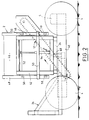
- the upright 2 of the frame 1 in the form of a gantry of the machine comprises a beam 40 carrying the wheels 4 at its ends.
- the beam 40 forms the casing for the pinions 8,9 and the chain 10 for transmitting the rotational movement of the hydraulic motor 5 to the corresponding wheels 4 (FIG. 1).
- a frame 42 On the beam 40 is welded a frame 42. On the frame 42 is slidably mounted another frame 46 of the frame carrying the conveyor 12 and formed of two vertical rails 48 guided by rollers such as 50 carried by the frame 42.
- the vertical rails 48 are interconnected by crosspieces 52, 53, one of which 52 is connected to the rod a lifting cylinder 54, the body of which is connected to the base of the frame 42.
- the amount 3 of the gantry shown in Figure 3 is similar to the amount 2 so that by acting on the two cylinders 54 connecting the frames 42 with the frames 46 of the gantry can be adjusted in height of the conveyor 12 to him allow to turn swaths of variable height from the swath base to the top.
- the wheels 4 on the right of the machine located opposite the coupling device 24 are mounted at the ends of the corresponding beam 40 by means of hinges 20 which, as shown in more detail in FIG. 4, each have a pin 21 forming an axis articulation engaged in lugs 56 provided at each end of the beam 40 and a branch 22 secured to the axis of the wheel 4.
- the branch 22 of the articulation hinge is constituted by a U-shaped section of section fixed by its core to the axis of the wheel 4 and whose wings 57 have a spacing slightly greater than the height of the beam 40 in order to allow applying the core of the branch 22 against the outer wall of the latter.
- the core of the branch 22 has a circular orifice in which is disposed a disc 58 integral with the hub of the wheel 4 and which has holes 59 for coupling with fingers 60 of a complementary coupling disc 61 carried by a short shaft 62 which passes through the side wall of the beam 40 and which is rotated by the hydraulic motor 6 via the transmission means with pinions 8, 9 and corresponding chain 10.
- the fingers 60 are made retractable against the action of strong return springs in the extended position (not shown), which allows a easy engagement of the fingers 60 in the coupling holes 59 carried by the disc 58 integral with the hub of each right wheel 4 of the machine, during the passage of these wheels from their transport position to the working position of the machine.
- each of the branches 22 of the articulation hinges of the right wheels 4 on their beam 40 is connected to the rod of a jack 64 whose body is articulated on the beam 40.
- the jack 64 is intended to pass each right wheel 4 from its transport position shown in FIG. 3 in which the coupling means 58, 59 of the wheel are not in engagement with the complementary driving coupling means 60 , 61 shown in Figure 4, in its working position, parallel to the beam 40 and in which the aforementioned coupling means engage and make the wheel 4 drive.
- the coupling device of the machine according to the invention is shown in more detail in FIGS. 5 and 6.
- the beams 66 are joined by a spacer 67 which comprises a pivot 68 for articulation of the coupling device 26 of the tractor by means of a spacer 69 carrying at its ends journals 69a for articulation of parallel branches 70 of the device coupling 26 connected to the tractor 28 ( Figures 1 and 5).
- the branches 70 comprise pins 71 for articulation with the traction bars of the tractor 28.
- FIG. 6 This arrangement appears more clearly in FIG. 6 in which it can be seen that the coupling devices 24, 26 of the machine according to the invention and of the tractor 28 are in fact constituted by cradles in welded wire mesh.
- the cradle integral with the machine is formed of parallel beams 66 arranged horizontally and joined to the sliding frame 42 by means of inclined beams 72.
- the cradle thus formed supports the bevel gear 34.
- the branches 70 of the coupling device 26 associated with the tractor are also stiffened by inclined reinforcing bars 74 welded between an intermediate zone of each branch 70 and the upper ends of vertical bars 75 also connected by welding to the end of each branch 70 opposite the coupling device 24 of the machine and carrying the articulations 71 engaged in hooks 76 of the drawbars 77 of the tractor 28.
- the vertical bars 75 are joined by welding through a crosspiece 78 which carries a hinge 79 with the rod of a jack 80 for transferring the load from the rear wheels of the tractor to the left wheels of the machine for turning over the swaths according to the invention, the operation of which will be described with reference to FIGS. 7 and 7A.
- the cylinder 80 is substituted for the push bar normally arranged at this location.
- the vertical bars 75 constitute, with the cross-member 78 and with a cross-member 81 carrying the articulation pins 71, an upright of the coupling device 26 by means of which it is connected to the tractor 28.
- Stabilizing bars 86 connect the base of the upright to connection points 87 of the tractor frame 28.
- FIG. 6 also shows the pipes for transporting pressurized fluid and a control valve 84 for the various jacks such as the jacks 54 for raising and lowering the frame 1 of the conveyor 12 and the jacks 64 for changing the position of the wheels. 4 on the right between the working state and the transport state of the machine and the load transfer cylinder 80.
- FIG. 7 shows a diagram of the means for transferring the load from the rear wheels of the tractor 28 to the left wheels of the machine according to the invention.
- the hitch 26 linked to the tractor 28 and more particularly the horizontal branches 70 thereof, is connected to the hitch 24 secured to the machine by means of the vertical pivot axis 68 by the intermediate of which and of the spacer 69 it is supported on the coupling 24.
- the jack 80, the draw bars 77 of the tractor and the vertical upright 75, 78, 81 of the hitch 26 linked to the tractor form a sort of deformable quadrilateral, three sides of which are the draw bars 77, the vertical bars 75 the amount and the distance between the connection points 82 and 85 of the drawbars 77 and the body of the jack 80 with the chassis of the tractor have constant lengths and one side, namely the jack 80 has a variable length.
- the stabilization bars 86 fixed at the connection points 87 on the chassis of the tractor and at the end of the upright 75,78,81 connected to the traction bars 77 ensure the rigidity of the traction bars.
- the actuator 80 is actuated, the lengthening of which relative to its rest state causes the application of a force on the crosspiece 78 connecting the vertical bars 75 and the transmission of this force by the non-deformable triangles formed by the branches 70, the vertical bars 75 and the reinforcement bars 74, to the pivot 68 connecting between the coupling device 26 of the tractor and the coupling device 24 of the machine.
- the weight of the windrow turning machine according to the invention is of the order of 2 tonnes while that of the tractor associated with the machine is 4 tonnes.
- the right wheels then become the rear wheels.
- the machine then rests on the rear wheels and can therefore be towed by the tractor at a speed between 1.5 km / h and 30 km / h.
- a free wheel (not shown) is interposed between each motor and its corresponding reduction gear.
- This device comprises the two hydraulic motors 5 and 6 for driving the left and right wheels of the machine supplied with pressurized fluid from the hydraulic pump of the tractor 28 (FIG. 1) not shown by means of a flow divider 90 connected on the one hand to a circuit 92 for supplying the left motor 5 and on the other hand to a circuit 94 for supplying the right motor 6 via a distributor 96 having a single lever drive wheels 97.
- the distributor 96 is mounted on the machine but it is accessible from the seat of the tractor 28.
- the distributor ensures the connection of the tractor pump with the two motors 5 and 6 which rotate at the same speed and which ensure the movement of the machine in a straight line in the working position.
- the dispenser lever 97 is in its stable central position.
- FIG. 8A shows the distributor 96 in a right turn control position in which the right motor 6 is not supplied while the left motor 5 alone is supplied.
- Figure 8B shows the distributor 96 in a left turn control position in which the right engine is powered while the left engine is not.
- FIG. 8C shows the distributor in the differential position in which none of the hydraulic motors is supplied. In this position, no work is required on the wheels 4. They are crazy.
- the position of the distributor 96 is changed by a single operating lever 97 which, in addition to the normal working position O, positions 1 and 2 corresponding respectively to the right and left turns and a notched position 3 corresponding to the differential state of non-drive of the wheels 4.
Landscapes
- Life Sciences & Earth Sciences (AREA)
- Chemical & Material Sciences (AREA)
- Soil Sciences (AREA)
- Biochemistry (AREA)
- Health & Medical Sciences (AREA)
- Engineering & Computer Science (AREA)
- Environmental Sciences (AREA)
- Biotechnology (AREA)
- Chemical Kinetics & Catalysis (AREA)
- General Chemical & Material Sciences (AREA)
- Microbiology (AREA)
- Molecular Biology (AREA)
- Organic Chemistry (AREA)
- Agricultural Machines (AREA)
- Sowing (AREA)
Applications Claiming Priority (2)
| Application Number | Priority Date | Filing Date | Title |
|---|---|---|---|
| FR9501995 | 1995-02-21 | ||
| FR9501995A FR2730601B1 (fr) | 1995-02-21 | 1995-02-21 | Machine a retourner les andains, notamment de fumier |
Publications (2)
| Publication Number | Publication Date |
|---|---|
| EP0728719A1 true EP0728719A1 (de) | 1996-08-28 |
| EP0728719B1 EP0728719B1 (de) | 2001-10-24 |
Family
ID=9476364
Family Applications (1)
| Application Number | Title | Priority Date | Filing Date |
|---|---|---|---|
| EP19960400357 Expired - Lifetime EP0728719B1 (de) | 1995-02-21 | 1996-02-21 | Umsetzmaschine für Dung- oder Kompostschwaden |
Country Status (4)
| Country | Link |
|---|---|
| EP (1) | EP0728719B1 (de) |
| DE (1) | DE69616109T2 (de) |
| ES (1) | ES2162987T3 (de) |
| FR (1) | FR2730601B1 (de) |
Cited By (1)
| Publication number | Priority date | Publication date | Assignee | Title |
|---|---|---|---|---|
| CN113853958A (zh) * | 2021-11-11 | 2021-12-31 | 山东农业大学 | 一种丘陵果园单轨自走式枝条粉碎机及枝条再利用方法 |
Families Citing this family (1)
| Publication number | Priority date | Publication date | Assignee | Title |
|---|---|---|---|---|
| CN109644596A (zh) * | 2019-02-21 | 2019-04-19 | 王志坚 | 秸秆有机利用一体机 |
Citations (4)
| Publication number | Priority date | Publication date | Assignee | Title |
|---|---|---|---|---|
| US4306686A (en) * | 1979-11-27 | 1981-12-22 | Scarab Manufacturing And Leasing, Inc. | Compost treatment apparatus |
| US4396292A (en) * | 1980-01-23 | 1983-08-02 | Bancohio National Bank | Windrowing-type composting apparatus |
| DE4215599A1 (de) * | 1992-05-12 | 1993-11-18 | Heissenberger & Pretzler Gmbh | Kompostwendemaschine |
| WO1994001995A1 (en) * | 1992-07-21 | 1994-02-03 | Glaze Bradley S | An improved compost mixing and aerating apparatus |
-
1995
- 1995-02-21 FR FR9501995A patent/FR2730601B1/fr not_active Expired - Fee Related
-
1996
- 1996-02-21 EP EP19960400357 patent/EP0728719B1/de not_active Expired - Lifetime
- 1996-02-21 DE DE1996616109 patent/DE69616109T2/de not_active Expired - Lifetime
- 1996-02-21 ES ES96400357T patent/ES2162987T3/es not_active Expired - Lifetime
Patent Citations (4)
| Publication number | Priority date | Publication date | Assignee | Title |
|---|---|---|---|---|
| US4306686A (en) * | 1979-11-27 | 1981-12-22 | Scarab Manufacturing And Leasing, Inc. | Compost treatment apparatus |
| US4396292A (en) * | 1980-01-23 | 1983-08-02 | Bancohio National Bank | Windrowing-type composting apparatus |
| DE4215599A1 (de) * | 1992-05-12 | 1993-11-18 | Heissenberger & Pretzler Gmbh | Kompostwendemaschine |
| WO1994001995A1 (en) * | 1992-07-21 | 1994-02-03 | Glaze Bradley S | An improved compost mixing and aerating apparatus |
Cited By (1)
| Publication number | Priority date | Publication date | Assignee | Title |
|---|---|---|---|---|
| CN113853958A (zh) * | 2021-11-11 | 2021-12-31 | 山东农业大学 | 一种丘陵果园单轨自走式枝条粉碎机及枝条再利用方法 |
Also Published As
| Publication number | Publication date |
|---|---|
| FR2730601B1 (fr) | 1997-04-30 |
| FR2730601A1 (fr) | 1996-08-23 |
| DE69616109D1 (de) | 2001-11-29 |
| DE69616109T2 (de) | 2002-05-29 |
| ES2162987T3 (es) | 2002-01-16 |
| EP0728719B1 (de) | 2001-10-24 |
Similar Documents
| Publication | Publication Date | Title |
|---|---|---|
| EP2699074B1 (de) | Landwirtschaftliche maschine mit verbesserter faltvorrichtung | |
| FR2620298A1 (fr) | Moissonneuse-batteuse automotrice comprenant un mecanisme de coupe subdivise en deux | |
| FR2668881A1 (fr) | Machine agricole, en particulier faucheuse, s'adaptant aisement au relief du terrain et comportant un carter pivotant. | |
| EP1496734B1 (de) | Heuwerbungsmaschine | |
| EP1290936B1 (de) | Heuwerbungsmaschine | |
| FR2736503A1 (fr) | Machine agricole, notamment faneuse a rateaux rotatifs multiples | |
| EP0692185B1 (de) | Heuwerbungsmaschine, namentlich ein Schwader mit gesteuerten Zinkentragarmen | |
| EP0514302B1 (de) | Verbesserter Pflanzenschwader | |
| FR2731872A1 (fr) | Materiel agricole pour la recolte de fruits portes par des arbres ou arbustes | |
| FR2740652A1 (fr) | Machine de fenaison comportant au moins un rotor d'andainage et permettant notamment une meilleure adaptation du rotor au relief du terrain | |
| EP0728719B1 (de) | Umsetzmaschine für Dung- oder Kompostschwaden | |
| FR2664127A1 (fr) | Machine agricole, notamment une andaineuse de vegetaux, a largeur de travail reglable. | |
| FR2541647A1 (fr) | Tracteur, en particulier tracteur agricole | |
| FR2505681A1 (fr) | Appareil de pulverisation | |
| EP0797913B1 (de) | Heuwerbungsmaschine | |
| EP0857413B1 (de) | Heuwerbungsmaschine | |
| FR2705861A1 (fr) | Machine de fenaison avec un dispositif de transport déplaçable. | |
| EP1269826B1 (de) | Heuwerbungsmaschine | |
| FR2547976A1 (fr) | Dispositif pour deplacer des vegetaux se trouvant sur le sol | |
| EP0654209B1 (de) | Heuwerbungsmaschine | |
| FR2551016A1 (de) | ||
| EP1013161B1 (de) | Heuwerbungsmaschine | |
| FR2731873A1 (fr) | Machine de fenaison, notamment une faneuse de vegetaux, transposable dans plusieurs positions | |
| EP0811314B1 (de) | Landmaschine | |
| FR2901452A1 (fr) | Machine agricole pouvant etre attelee a l'arriere d'un tracteur par l'intermediaire d'une poutre semi-portee |
Legal Events
| Date | Code | Title | Description |
|---|---|---|---|
| PUAI | Public reference made under article 153(3) epc to a published international application that has entered the european phase |
Free format text: ORIGINAL CODE: 0009012 |
|
| AK | Designated contracting states |
Kind code of ref document: A1 Designated state(s): BE CH DE ES FR IT LI NL |
|
| 17P | Request for examination filed |
Effective date: 19970228 |
|
| 17Q | First examination report despatched |
Effective date: 19990707 |
|
| GRAG | Despatch of communication of intention to grant |
Free format text: ORIGINAL CODE: EPIDOS AGRA |
|
| GRAG | Despatch of communication of intention to grant |
Free format text: ORIGINAL CODE: EPIDOS AGRA |
|
| GRAH | Despatch of communication of intention to grant a patent |
Free format text: ORIGINAL CODE: EPIDOS IGRA |
|
| GRAH | Despatch of communication of intention to grant a patent |
Free format text: ORIGINAL CODE: EPIDOS IGRA |
|
| GRAA | (expected) grant |
Free format text: ORIGINAL CODE: 0009210 |
|
| AK | Designated contracting states |
Kind code of ref document: B1 Designated state(s): BE CH DE ES FR IT LI NL |
|
| PG25 | Lapsed in a contracting state [announced via postgrant information from national office to epo] |
Ref country code: NL Free format text: LAPSE BECAUSE OF FAILURE TO SUBMIT A TRANSLATION OF THE DESCRIPTION OR TO PAY THE FEE WITHIN THE PRESCRIBED TIME-LIMIT Effective date: 20011024 Ref country code: IT Free format text: LAPSE BECAUSE OF FAILURE TO SUBMIT A TRANSLATION OF THE DESCRIPTION OR TO PAY THE FEE WITHIN THE PRE;WARNING: LAPSES OF ITALIAN PATENTS WITH EFFECTIVE DATE BEFORE 2007 MAY HAVE OCCURRED AT ANY TIME BEFORE 2007. THE CORRECT EFFECTIVE DATE MAY BE DIFFERENT FROM THE ONE RECORDED.SCRIBED TIME-LIMIT Effective date: 20011024 |
|
| REG | Reference to a national code |
Ref country code: CH Ref legal event code: EP |
|
| REF | Corresponds to: |
Ref document number: 69616109 Country of ref document: DE Date of ref document: 20011129 |
|
| REG | Reference to a national code |
Ref country code: ES Ref legal event code: FG2A Ref document number: 2162987 Country of ref document: ES Kind code of ref document: T3 |
|
| PG25 | Lapsed in a contracting state [announced via postgrant information from national office to epo] |
Ref country code: LI Free format text: LAPSE BECAUSE OF NON-PAYMENT OF DUE FEES Effective date: 20020228 Ref country code: CH Free format text: LAPSE BECAUSE OF NON-PAYMENT OF DUE FEES Effective date: 20020228 Ref country code: BE Free format text: LAPSE BECAUSE OF NON-PAYMENT OF DUE FEES Effective date: 20020228 |
|
| NLV1 | Nl: lapsed or annulled due to failure to fulfill the requirements of art. 29p and 29m of the patents act | ||
| PLBE | No opposition filed within time limit |
Free format text: ORIGINAL CODE: 0009261 |
|
| STAA | Information on the status of an ep patent application or granted ep patent |
Free format text: STATUS: NO OPPOSITION FILED WITHIN TIME LIMIT |
|
| BERE | Be: lapsed |
Owner name: S.A. JEANTIL Effective date: 20020228 |
|
| REG | Reference to a national code |
Ref country code: CH Ref legal event code: PL |
|
| 26N | No opposition filed | ||
| PGFP | Annual fee paid to national office [announced via postgrant information from national office to epo] |
Ref country code: ES Payment date: 20090220 Year of fee payment: 14 |
|
| REG | Reference to a national code |
Ref country code: ES Ref legal event code: FD2A Effective date: 20110310 |
|
| PG25 | Lapsed in a contracting state [announced via postgrant information from national office to epo] |
Ref country code: ES Free format text: LAPSE BECAUSE OF NON-PAYMENT OF DUE FEES Effective date: 20110309 |
|
| PG25 | Lapsed in a contracting state [announced via postgrant information from national office to epo] |
Ref country code: ES Free format text: LAPSE BECAUSE OF NON-PAYMENT OF DUE FEES Effective date: 20100222 |
|
| PGFP | Annual fee paid to national office [announced via postgrant information from national office to epo] |
Ref country code: DE Payment date: 20120320 Year of fee payment: 17 |
|
| REG | Reference to a national code |
Ref country code: DE Ref legal event code: R119 Ref document number: 69616109 Country of ref document: DE Effective date: 20130903 |
|
| PG25 | Lapsed in a contracting state [announced via postgrant information from national office to epo] |
Ref country code: DE Free format text: LAPSE BECAUSE OF NON-PAYMENT OF DUE FEES Effective date: 20130903 |
|
| PGFP | Annual fee paid to national office [announced via postgrant information from national office to epo] |
Ref country code: FR Payment date: 20141211 Year of fee payment: 20 |